
'87 Intake Removal, Repairs, Installation Procedure (w/pics)


 01-17-2009, 10:00 AM
#18
Three Wheelin'
Thread Starter
Join Date: Sep 2007
Location: Ridgecrest, California
Posts: 1,363
Likes: 0
Received 146 Likes
on
30 Posts
Disconnect the vacuum feed line to the 7-port vacuum manifold at the rear of the engine.
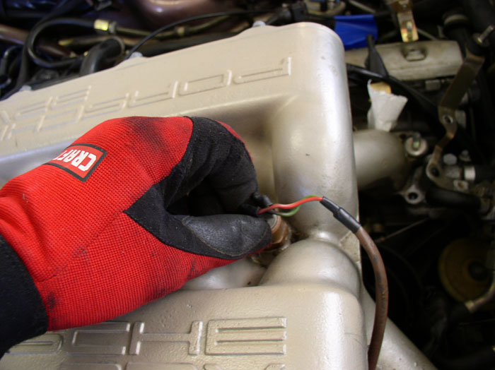
Disconnect the wires from the air temp sensor on the top of the intake. These are spade connectors and it doesn't matter which wire goes to which terminal so no need to mark these.
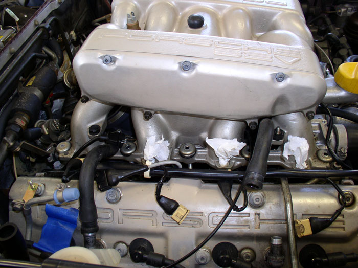
Before prying the intake up from the heads, it's a good idea to vacuum out any loose debris from around the bottom of the intake runners so that it doesn't fall into the heads while you're manuevering the intake around in the next few steps.
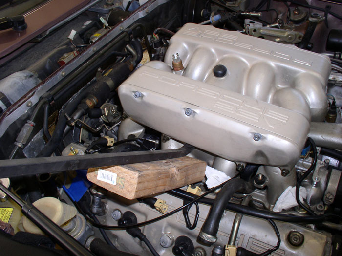
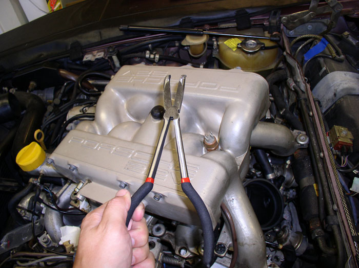
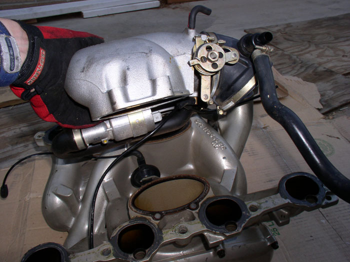
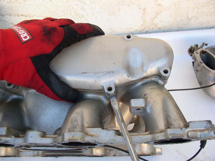
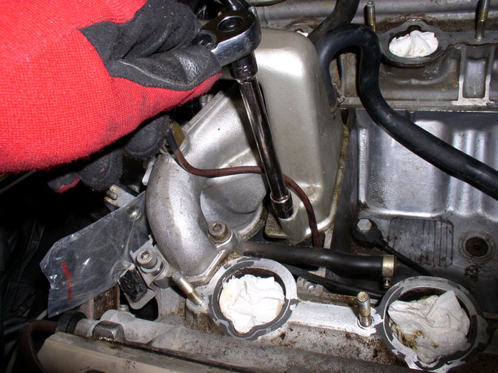
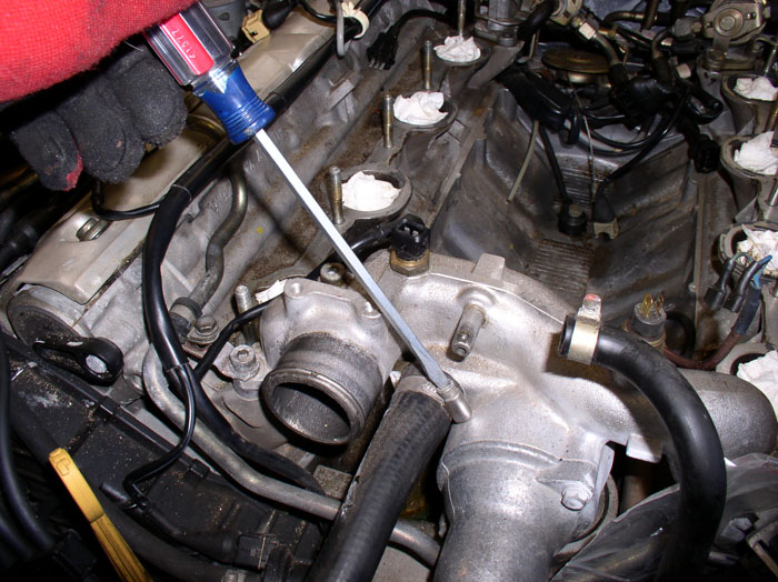
The intake may have taken a liking to the heads and won't want to come off easily. I used a short 2X4 and long prybar to lever some force from underneath the intake to break the intake free. You can place the 2X4 on the head casting that protrudes out from under the cam cover about mid way on the head (where the 2X4 is shown here) rather than resting it on the cam cover.
Once the intake is free, lift it up enough to rest it on top of the intake mounting studs. This will allow you some room to remove a few more connections before extracting the intake.
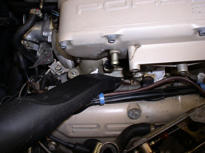
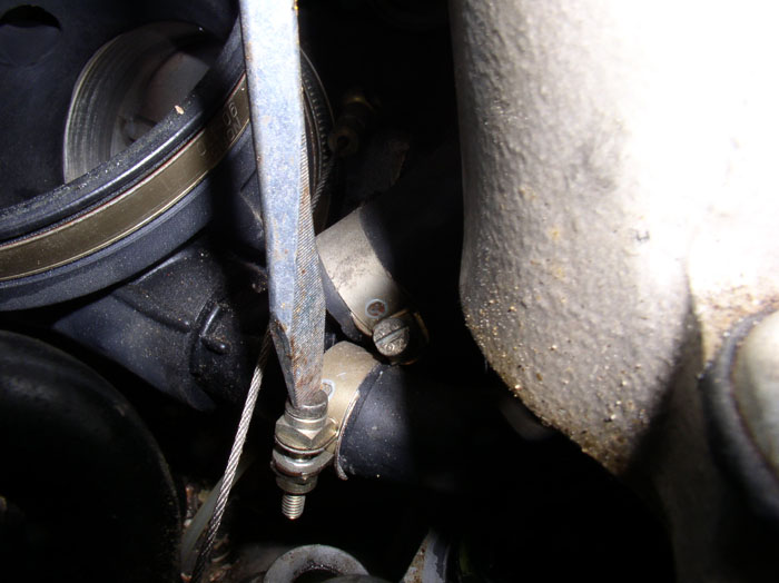
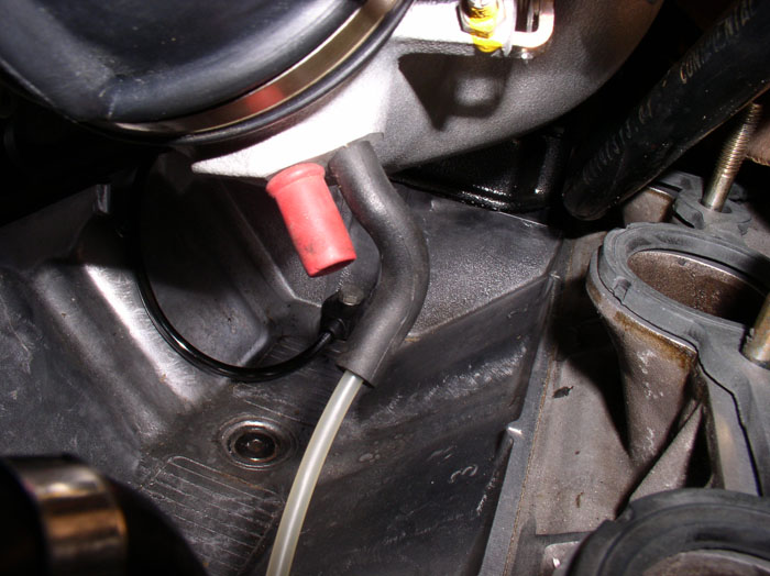
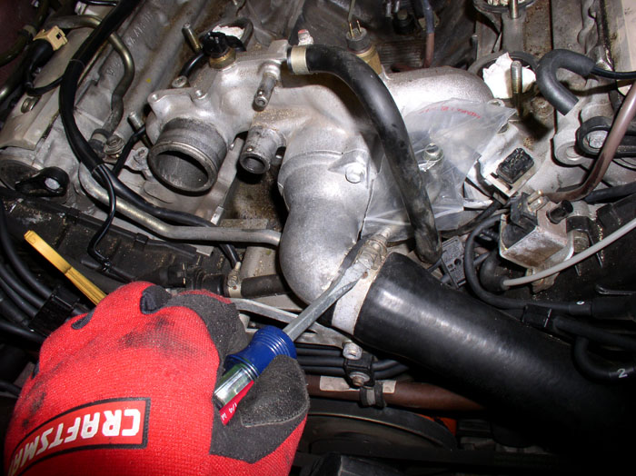
Next, you'll need to disconnect the hose that arrives at the intake from the oil filler neck and fuel vent solenoid (the 3 way hose). Use a flat blade screwdriver and lift the driver's side of the intake slightly to gain a little work room.
Now, while you're still on the driver's side, remove the Throttle Position Sensor electrical connection. Lift the intake slightly to gain work room and grasp the connector and pull rearward while rocking up and down.
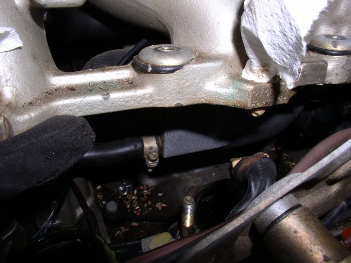
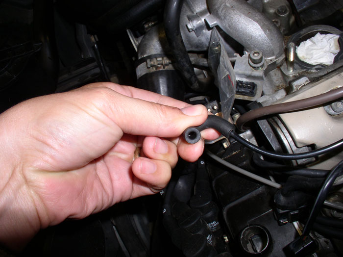
Now over to the passenger side. You'll need to remove the breather hose that arrives at the Air Guide Cowl from the oil filler neck base. It should be the hose that is closest to the firewall but you can confirm this by tracing it. The other hose at this "Y" connector is the breather hose that runs to the cam cover - you can leave that one attached. Loosen the clamp with a screwdriver and disconnect the hose.
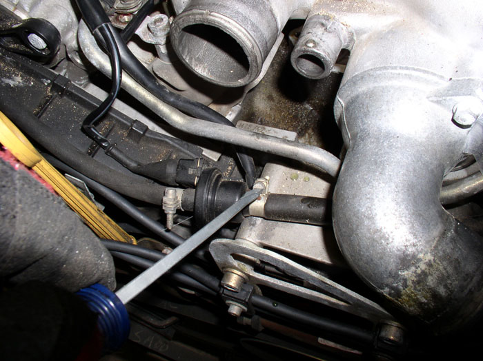
Next, lift the passenger side of the intake up enough to gain access to the underside of the throttle body and you will find an elbow and vacuum line that runs to the air pump diverter valve. Disconnect the elbow from the throttle body.
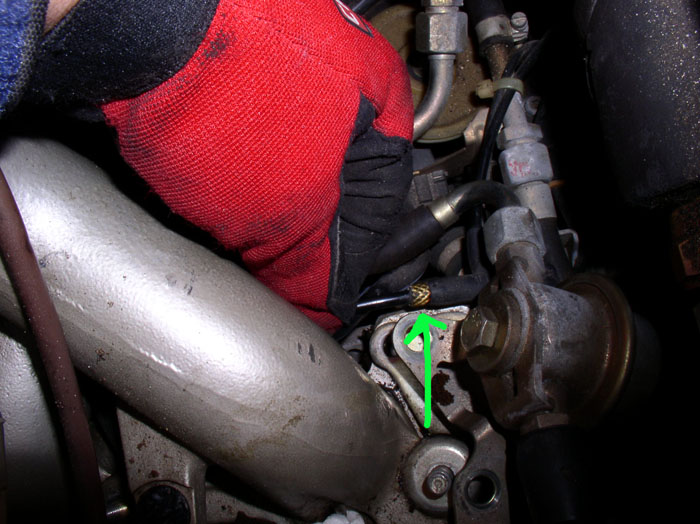
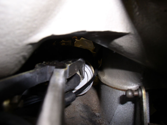
Now to disconnect the ISV electrical plug. There is a special tool called for in the WSM but I didn't have one and couldn't locate one easily - although I believe you can get them. I used an extra long pair of needle nose pliers with a 90 degree bend at the plier ends. At this point, the only connection left is the ISV electrical plug. Lift and rotate the intake so you can see/access the plug to the ISV. I rotated it toward the driver's side because I'm right handed and this provided a good orientation to access the plug with my right hand.
Use your tool of choice (or hand if it's small enough) to reach in and grasp the connector and pull while rocking side to side. If you're using pliers, be careful not to grasp too hard because the plug housing on the harness end may be brittle and could break.
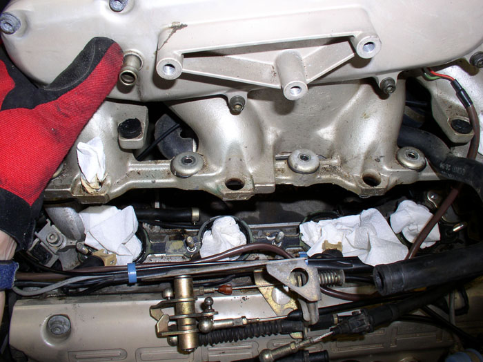
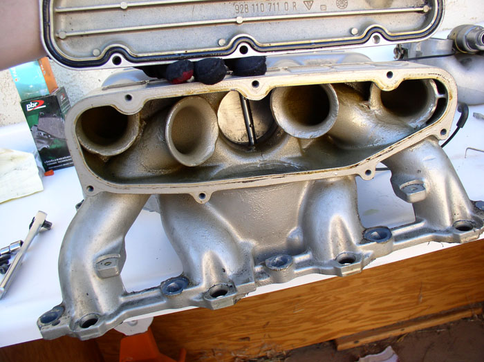
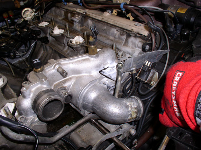
With the ISV plug disconnected, you should be able to lift and remove the intake. Immediately plug the intake ports on the head to prevent debris from falling into the head - or worse, combustion chamber.
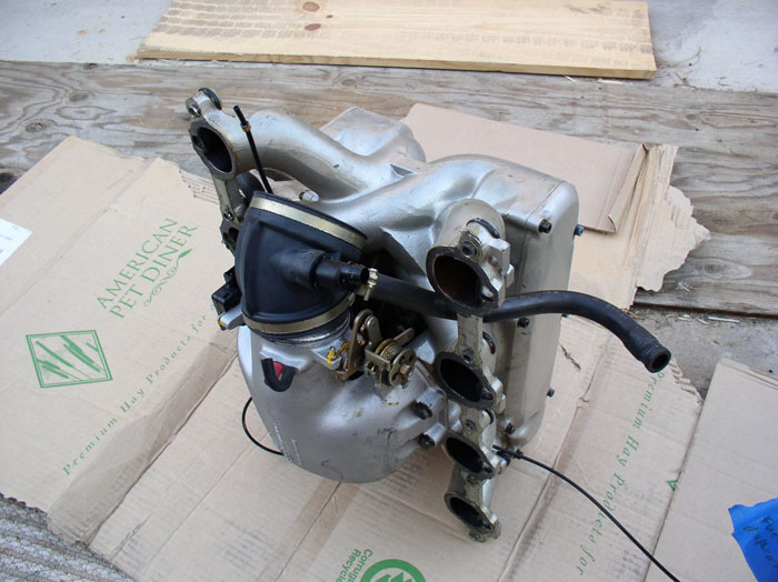
Now you can stand the intake on end to remove a few more parts. I needed to completely disassemble the intake because I planned to refinish it. I chose to go the Powder Coating route rather than paint.
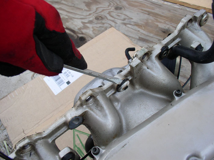
First, remove the intake to head thrust washers. There's 3 parts to these - the metal umbrella cap, the rubber thrust washer, and the metal sleeve insert. They may come of in one piece or in separates. Mine were firmly attached to the intake so I used a screwdriver to carefully pry them off.
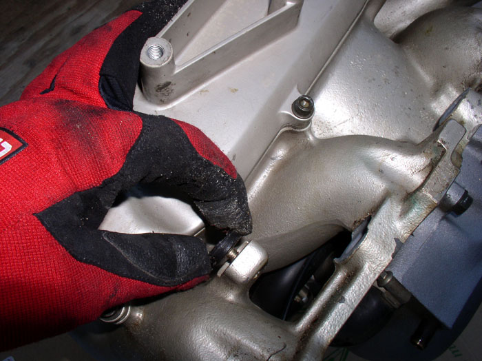
Also remove the fuel rail mounting studs from the intake (4). It's a rubber bushing with threaded studs on both sides. Use a pair of pliers to grip the rubber bushing (or what's left of it) and unscrew from the intake.
continued.....
Disconnect the wires from the air temp sensor on the top of the intake. These are spade connectors and it doesn't matter which wire goes to which terminal so no need to mark these.
Before prying the intake up from the heads, it's a good idea to vacuum out any loose debris from around the bottom of the intake runners so that it doesn't fall into the heads while you're manuevering the intake around in the next few steps.
The intake may have taken a liking to the heads and won't want to come off easily. I used a short 2X4 and long prybar to lever some force from underneath the intake to break the intake free. You can place the 2X4 on the head casting that protrudes out from under the cam cover about mid way on the head (where the 2X4 is shown here) rather than resting it on the cam cover.
Once the intake is free, lift it up enough to rest it on top of the intake mounting studs. This will allow you some room to remove a few more connections before extracting the intake.
Next, you'll need to disconnect the hose that arrives at the intake from the oil filler neck and fuel vent solenoid (the 3 way hose). Use a flat blade screwdriver and lift the driver's side of the intake slightly to gain a little work room.
Now, while you're still on the driver's side, remove the Throttle Position Sensor electrical connection. Lift the intake slightly to gain work room and grasp the connector and pull rearward while rocking up and down.
Now over to the passenger side. You'll need to remove the breather hose that arrives at the Air Guide Cowl from the oil filler neck base. It should be the hose that is closest to the firewall but you can confirm this by tracing it. The other hose at this "Y" connector is the breather hose that runs to the cam cover - you can leave that one attached. Loosen the clamp with a screwdriver and disconnect the hose.
Next, lift the passenger side of the intake up enough to gain access to the underside of the throttle body and you will find an elbow and vacuum line that runs to the air pump diverter valve. Disconnect the elbow from the throttle body.
Now to disconnect the ISV electrical plug. There is a special tool called for in the WSM but I didn't have one and couldn't locate one easily - although I believe you can get them. I used an extra long pair of needle nose pliers with a 90 degree bend at the plier ends. At this point, the only connection left is the ISV electrical plug. Lift and rotate the intake so you can see/access the plug to the ISV. I rotated it toward the driver's side because I'm right handed and this provided a good orientation to access the plug with my right hand.
Use your tool of choice (or hand if it's small enough) to reach in and grasp the connector and pull while rocking side to side. If you're using pliers, be careful not to grasp too hard because the plug housing on the harness end may be brittle and could break.
With the ISV plug disconnected, you should be able to lift and remove the intake. Immediately plug the intake ports on the head to prevent debris from falling into the head - or worse, combustion chamber.
Now you can stand the intake on end to remove a few more parts. I needed to completely disassemble the intake because I planned to refinish it. I chose to go the Powder Coating route rather than paint.
First, remove the intake to head thrust washers. There's 3 parts to these - the metal umbrella cap, the rubber thrust washer, and the metal sleeve insert. They may come of in one piece or in separates. Mine were firmly attached to the intake so I used a screwdriver to carefully pry them off.
Also remove the fuel rail mounting studs from the intake (4). It's a rubber bushing with threaded studs on both sides. Use a pair of pliers to grip the rubber bushing (or what's left of it) and unscrew from the intake.
continued.....
01-17-2009, 11:02 AM
#19
Three Wheelin'
Thread Starter
Join Date: Sep 2007
Location: Ridgecrest, California
Posts: 1,363
Likes: 0
Received 146 Likes
on
30 Posts
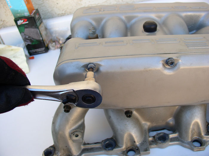
The throttle body is attached to the intake with 4 13mm bolts. Remove these next and....
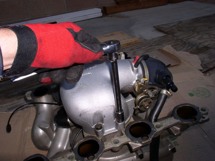
...the throttle body should come right off with no resistance. You will need to guide the breather hoses still attached to the air guid cowl through the intake runners as you're removing the throttle body.
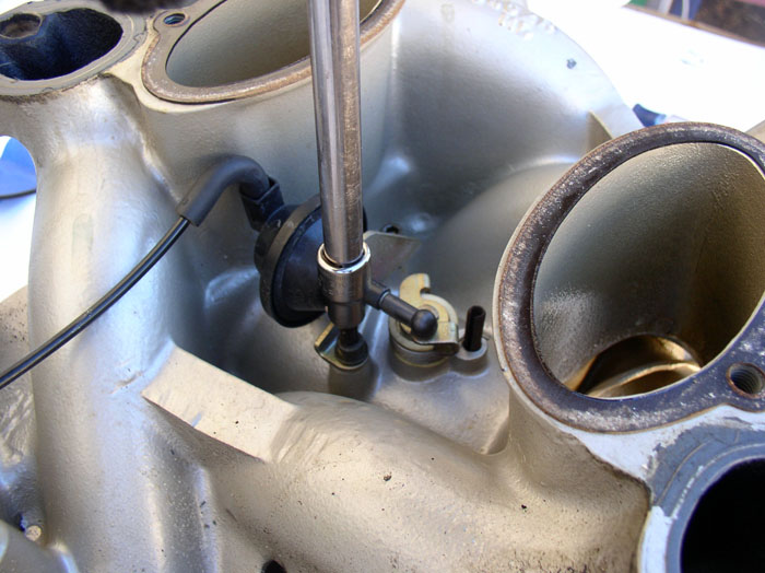
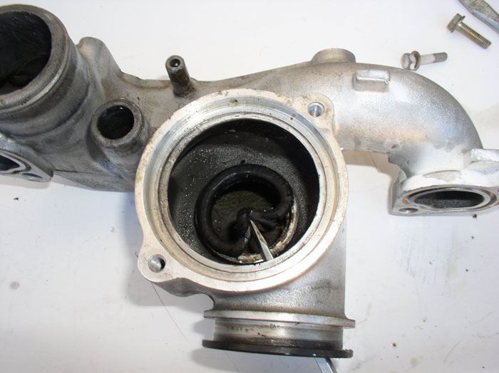
You should now have access to the flappy vacuum unit. If your tests earlier showed a leaking or sticking unit, you can inspect for leaks with the elbow and vacuum line here and remove the elbow from the unit and hook your vacuum pump directly to the diaphram and test for leaks. If the unit is leaking, put it on lthe order list.
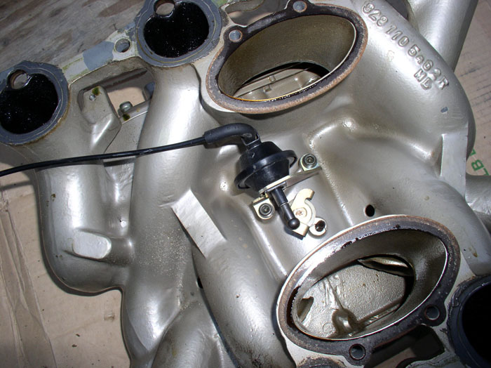
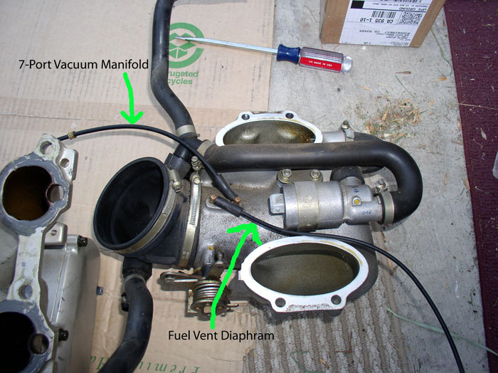
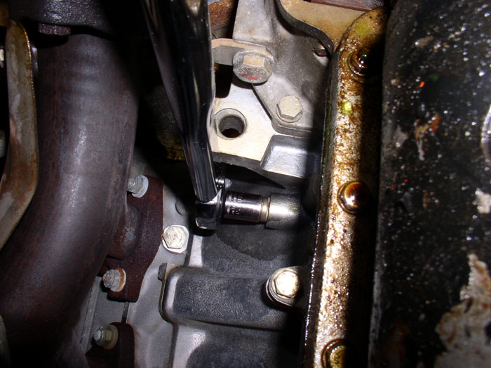
Under the throttle body you can inspect the ISV and hoses. There are two vacuum lines attached to the throttle body. The shorter line coming out the left goes to the 7-way vacuum manifold while the longer line goes to the fuel vent diaphram that is located next to the coolant reservoir.
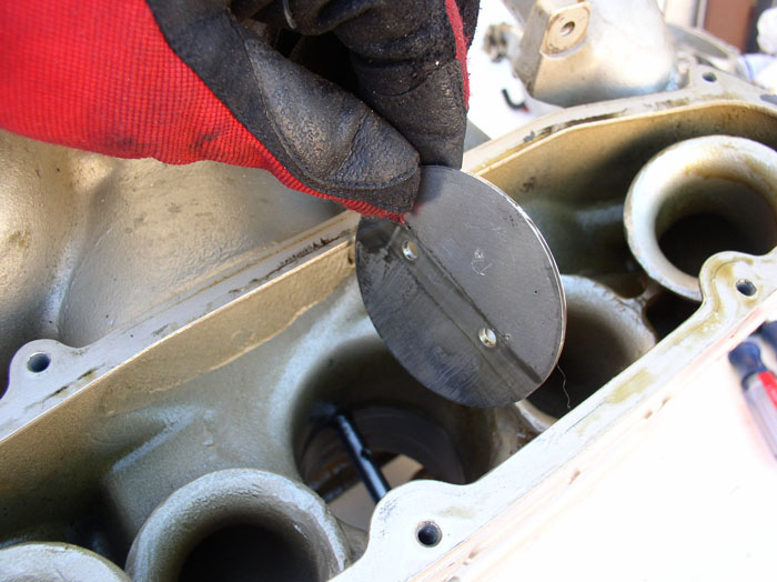
Next, remove the intake side cover plates. Use a 5mm allen head socket.
Gently pry up the cover plate with a flat blade screwdriver being careful not to mar the mating surfaces.
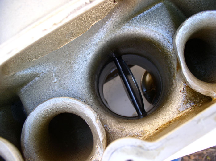
Once the plate is removed, you can see the internals of the intake including the flappy plate. If you noticed the flappy diaphram was sticking while operating it with the vacuum pump, you can investigate here by operating the vacuum unit with the vacuum pump and watching where the plate is getting hung.
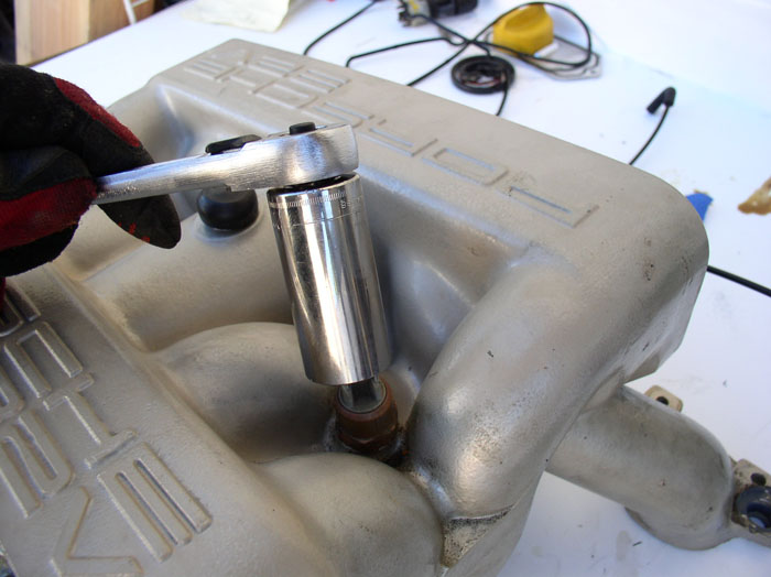
Next, remove the air temperature sensor from the top of the intake using a 22mm deep socket.
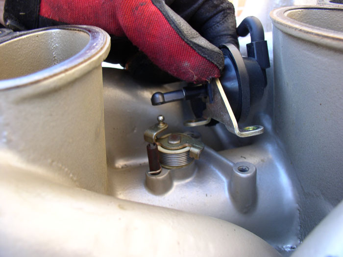
Now, remove the flappy vacuum unit. It's attached to the throttle body by two 5mm allen head bolts. Remove both of these.
Then, detach the ball connector on the diaphram from the lever arm of the flappy and remove the vacuum unit.
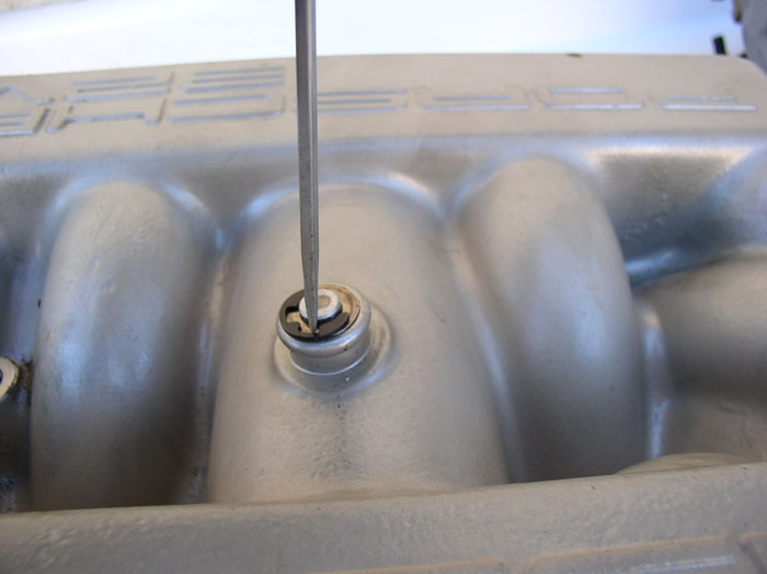
Remove the spring clip from the top of the intake using a flat blade screwdriver and be careful to catch the clip if it flies off.
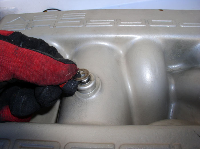
Remove the washer.....
Next, remove the flappy plate screws with a flat blade screwdriver.
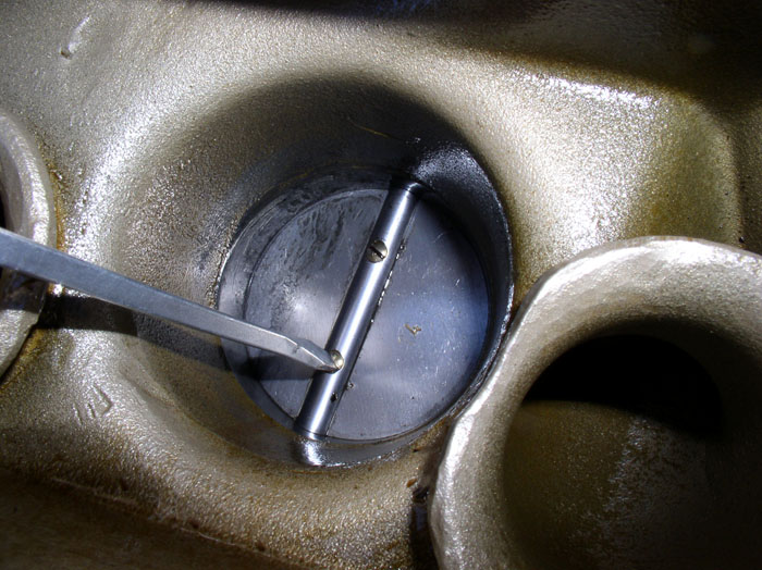
Then, rotate the plate 90 degrees.....
...and pull the flappy plate out. Note that the edges of the flappy plate are camfered slightly in order to seal better. It will be important to put the plate back in the the correct orientation. You can note the orientation by marking the plate directly with a marker or piece of tape (e.g., "driver's side" for the side that faces the driver's side of the car). Or, if you're feeling confident at this point (having removed your first intake), leave it unmarked and make sure the camfer is correct when you re-insert the plate back in. This is what I did but I found I still had a 50% chance of getting it right since the plate can be flipped like a coin and it can be rotated (like a wheel) 180 degrees. It didn't fit right at the first attempt to re-install so I flipped it like a coin, rotated it so the camfer was correct and it fit correctly.
continued.....(tonight - have to make a run out of town now in California - )
)
...the throttle body should come right off with no resistance. You will need to guide the breather hoses still attached to the air guid cowl through the intake runners as you're removing the throttle body.
You should now have access to the flappy vacuum unit. If your tests earlier showed a leaking or sticking unit, you can inspect for leaks with the elbow and vacuum line here and remove the elbow from the unit and hook your vacuum pump directly to the diaphram and test for leaks. If the unit is leaking, put it on lthe order list.
Under the throttle body you can inspect the ISV and hoses. There are two vacuum lines attached to the throttle body. The shorter line coming out the left goes to the 7-way vacuum manifold while the longer line goes to the fuel vent diaphram that is located next to the coolant reservoir.
Next, remove the intake side cover plates. Use a 5mm allen head socket.
Gently pry up the cover plate with a flat blade screwdriver being careful not to mar the mating surfaces.
Once the plate is removed, you can see the internals of the intake including the flappy plate. If you noticed the flappy diaphram was sticking while operating it with the vacuum pump, you can investigate here by operating the vacuum unit with the vacuum pump and watching where the plate is getting hung.
Next, remove the air temperature sensor from the top of the intake using a 22mm deep socket.
Now, remove the flappy vacuum unit. It's attached to the throttle body by two 5mm allen head bolts. Remove both of these.
Then, detach the ball connector on the diaphram from the lever arm of the flappy and remove the vacuum unit.
Remove the spring clip from the top of the intake using a flat blade screwdriver and be careful to catch the clip if it flies off.
Remove the washer.....
Next, remove the flappy plate screws with a flat blade screwdriver.
Then, rotate the plate 90 degrees.....
...and pull the flappy plate out. Note that the edges of the flappy plate are camfered slightly in order to seal better. It will be important to put the plate back in the the correct orientation. You can note the orientation by marking the plate directly with a marker or piece of tape (e.g., "driver's side" for the side that faces the driver's side of the car). Or, if you're feeling confident at this point (having removed your first intake), leave it unmarked and make sure the camfer is correct when you re-insert the plate back in. This is what I did but I found I still had a 50% chance of getting it right since the plate can be flipped like a coin and it can be rotated (like a wheel) 180 degrees. It didn't fit right at the first attempt to re-install so I flipped it like a coin, rotated it so the camfer was correct and it fit correctly.
continued.....(tonight - have to make a run out of town now in California -
)
 01-17-2009, 01:07 PM
#21
Rennlist Member
Thank You, Thank You, Thank You, Thank You, Thank You.....ect x928.
I am just starting this job this weekend. I have read through the existing guides and was thinking to myself how great it would be if Dwayne did one of his epic documentations. You are adding a wealth of info for us timid newbie 928 mechanics.
I am just starting this job this weekend. I have read through the existing guides and was thinking to myself how great it would be if Dwayne did one of his epic documentations. You are adding a wealth of info for us timid newbie 928 mechanics.
 01-17-2009, 02:51 PM
#24
Rennlist Member
Dwayne should be knighted for these contributions.
He's 3000 miles away, and a group of us engineers where I work on the east coast, general car enthusiasts, spent 15 minutes in a meeting at our place of business discussing the quality and comprehensiveness of his previous write-ups. We may have to call a special session to contemplate this one.
Glad to be associated with you, Dwayne, even if its only virtually!
Way to add value to a community.
The following users liked this post:
rahulsingh (01-14-2020)
01-17-2009, 03:17 PM
#25
Under the Lift
Lifetime Rennlist
Member
Lifetime Rennlist
Member
Hi Dwayne:
Genius work again. You'd think you'd been doing these all your life from the expertise you show in your write-up.
I'm glad you pointed out the problem with the injector harness plug wire clips. I've had them fly off into the great unknown. Once I did not notice one was gone until I had pulled the intake completely off, and I could not be sure it had not fallen down into one of the cylinders. So, I had to borrow a boroscope to make sure it had not gone down there. So, CAUTION is the word when dealing with these.
These clips are supposed to be held on by a dab of melted connector plastic peened over the clip on the backside. You can use a soldering iron to restore this melted dab so the clips will stay in-place. I've done it, although it can still chip off later. So, the best solution is to use aftermarket wire clips that have little "hands", as you mentioned, at the ends of the arms that are folded in 90 degrees so the clip cannot simply slide off. I have not found a source for the newer style wire clips independent of the connector, but I've bought quantities of the full connector with the revised wire clip for $2 each off eBay.
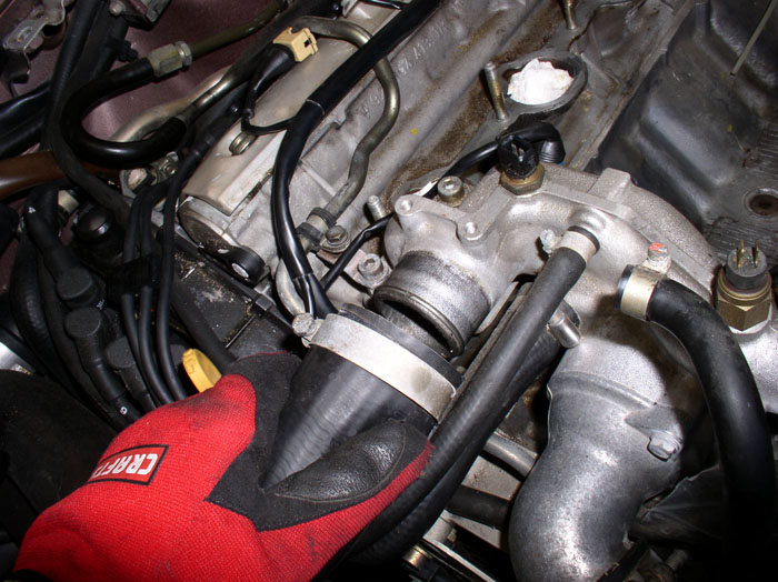
A sparkplug cap puller is a handy tool for easily removing stubborn injectors from the manifold.
Looking forward to the final installments of your complete intake refurb.
For those who admire Dwayne's excellent guides as much as I do, I have accumulated them online with Dwayne's authorization at a simple website called "Dwayne's Garage". I'll add this one as soon as Dwayne has finished it. Here's a link:
http://www.dwaynesgarage.norcal928.org/
Genius work again. You'd think you'd been doing these all your life from the expertise you show in your write-up.
I'm glad you pointed out the problem with the injector harness plug wire clips. I've had them fly off into the great unknown. Once I did not notice one was gone until I had pulled the intake completely off, and I could not be sure it had not fallen down into one of the cylinders. So, I had to borrow a boroscope to make sure it had not gone down there. So, CAUTION is the word when dealing with these.
These clips are supposed to be held on by a dab of melted connector plastic peened over the clip on the backside. You can use a soldering iron to restore this melted dab so the clips will stay in-place. I've done it, although it can still chip off later. So, the best solution is to use aftermarket wire clips that have little "hands", as you mentioned, at the ends of the arms that are folded in 90 degrees so the clip cannot simply slide off. I have not found a source for the newer style wire clips independent of the connector, but I've bought quantities of the full connector with the revised wire clip for $2 each off eBay.
A sparkplug cap puller is a handy tool for easily removing stubborn injectors from the manifold.
Looking forward to the final installments of your complete intake refurb.
For those who admire Dwayne's excellent guides as much as I do, I have accumulated them online with Dwayne's authorization at a simple website called "Dwayne's Garage". I'll add this one as soon as Dwayne has finished it. Here's a link:
http://www.dwaynesgarage.norcal928.org/
01-17-2009, 05:05 PM
#27
Drifting
Dwayne,
Bravo. This is fantastic stuff.
I did intake job last year and it's a salutary experience to see how smoothly you negotiated parts of the procedure whhich had me puzzled for a time (mainly removing the brackets for rear FPR and damper).
I'm also a big fan of Dave Chamberland's write-up which was my main guide, along with Fred O'Rourke's, but in the old "thousand word equivalence" it's brilliant the way you meticulously document each stage with clear photos.
My only query was that you disconnected the fuel line supply to the front damper. I'm pretty sure I didn't have to do this, and just left the damper in place (though had to undo the bracket so I could remove coolant crossover to replace gaskets).
I also like the way you were careful to plug things as soon as they were exposed. Had a guilty pang when I realised I didn't bag the fuel rails to prevent contamination (though they were put in a new and covered big plastic box I use for storing big parts during a project).
Thanks for creating such a valuable resource. I really think there's a market for creating a manual with all your write-ups included.
Can't wait for the other procedures to be posted.
Adrian
01-17-2009, 10:31 PM
#28
Three Wheelin'
Thread Starter
Join Date: Sep 2007
Location: Ridgecrest, California
Posts: 1,363
Likes: 0
Received 146 Likes
on
30 Posts
OK...I'm back. THANKS for all the great comments. I was thinking maybe there were too many pictures or too much detail but it's probably good to have sort of a database of pics that can be referenced in the future.
Now, back to the fun!
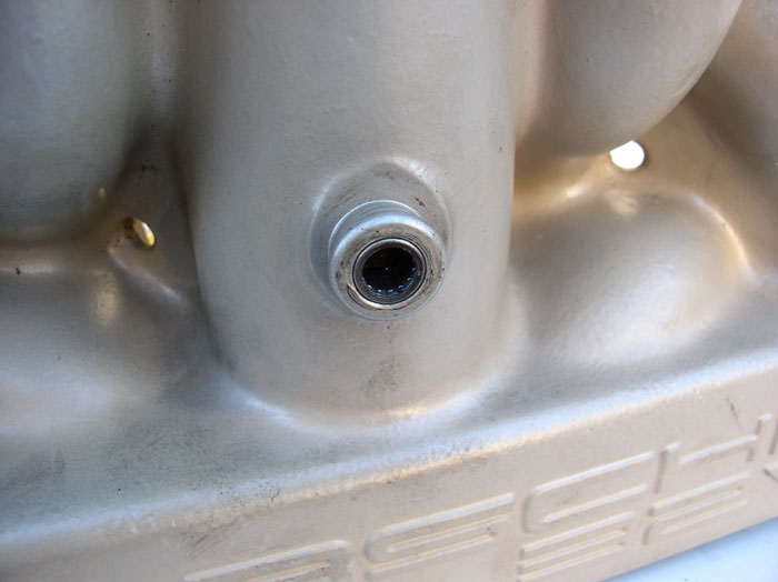
After you've taken out the flappy plate, pull the flappy spindle out from the bottom of the intake. Keep the spindle, washers and spring intact in a platic baggie. I have pics later of how mine went back together, if needed. You will notice a set of pressed in needle bearings at the top of the intake and at the bottom of the intake. These seem to do alright with age but the seals tend to wear out, dry out, disintegrate. There is a single seal for each bearing (top and bottom). When they no longer seal against the flappy spindle, it can be a source of false air, or vacuum leak. Roger sells new bearng units which have double seals - so twice as many seals as original. We'll be replacing these as well a little later in this post.
Being a newbie, I left the bearings in for the powder coating process not knowing how to take them out. After doing some research on Rennlist, I ran across a post from Shocki where he recommended leaving them in for powder coating so the bearing housing will act as a mask to keep the PC from getting in the bearing seat. Then just plan on replacing the bearings when the intake comes back. I felt much better! THANKS, Shocki!
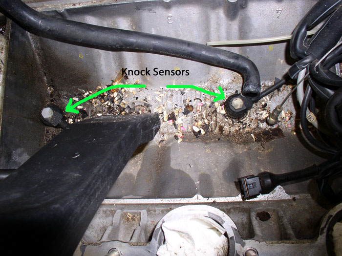
Now, back to the block. Vacuum the loose debris, if any, and perform any cleaning you might want to do while the old knock sensors are in place. We will be replacing the knock sensors on this job.
With the intake off, now's a good time to look at the hoses and vacuum lines for wear and possible replacement. If you're not planning on simply replacing everything as described early in this post, you'll want to check the hoses for cracks, bulges, soft spots, etc. I checked for softness by pinching them and then bent them like a pretzel to see if any cracks would show up. They all looked pretty good. At first, I thought I would just replace the worn ones. But after I saw the deep impressions the hose clamps made on most of the hoses and also noting that the original hose clamps seem to be designed to have a limit on clamping (i.e., the clamp would easily bottom out and with moderate force, I could twist the hose on some examples), I decided to simply replace all the hoses - so they went on the list.
After inspecting the elbows, I came to the same conclusion. Although the elbows did seem to be in better shape than the hoses, I replaced them anyway. Again, a matter of personal preference.
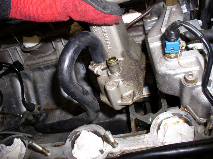
Removing the oil filler neck and water bridge are not mandatory while removing the intake. However, if you are experiencing leaks or planning on painting/powder coating, they'll have to come off. To remove the oil filler neck, remove the two 10mm bolts that hold the base to the block.
Carefully remove the filler neck from the block ensuring nothing falls into the crankcase. There is a baffle/gasket between the filler neck base and the block. Here it is still attached to the base of the filler neck. On this '87, it is a thin metal plate with an embedded gasket ring. I understand the part is no longer available but we'll talk about this item later.
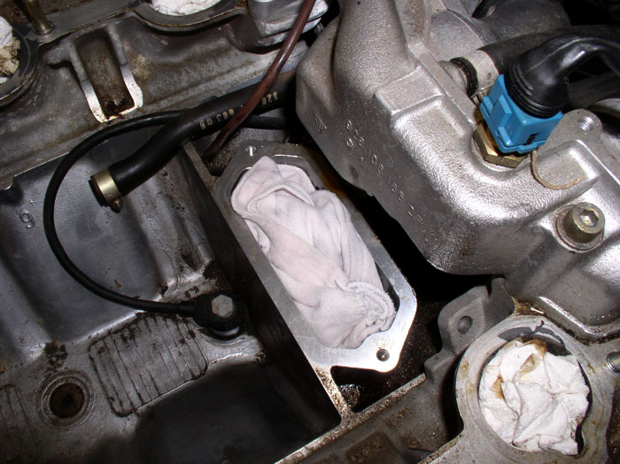
Directly after removing the filler neck, you can look down into the crankcase for anything unusual. Then stuff it with a clean rag to prevent debris from falling in.
Next, the water bridge. It's a good idea to drain some of the water from the radiator - enough to empty the reservoir - and the block so you don't have too much coolant leaking out when removing the bridge. Since I was also going to be doing the Timing Belt and Water Pump and removing the radiator as part of the job, I emptied all the coolant from the block and the radiator and the reservoir. You can drain the block by locating the drain plugs from underneath the engine. It's a 13mm bolt located toward the rear of the engine. There is one one each side of the block. Place a bucket under the engine at proximity and remove the drain plug. The drain plug comes with a sealing ring. Since these did not look like they have ever been removed, I re-used the sealing ring with no problems. However, if you would like to replace the ring, they can be ordered. When the block is finished draining, you can re-install the drain plugs and torque to 25.8 ftlbs, or 35 Newton meters.
Next, loosen the upper radiator hose clamp using a screwdriver or 10mm socket and remove the hose.
Loosen the bleeder hose clamp with a screwdriver and remove the hose.
Loosen the heater return hose clamp with a screwdriver and remove the hose.
Loosen the lower radiator hose clamp using a screwdriver or 10mm socket and remove the hose.
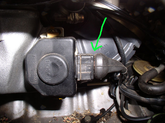
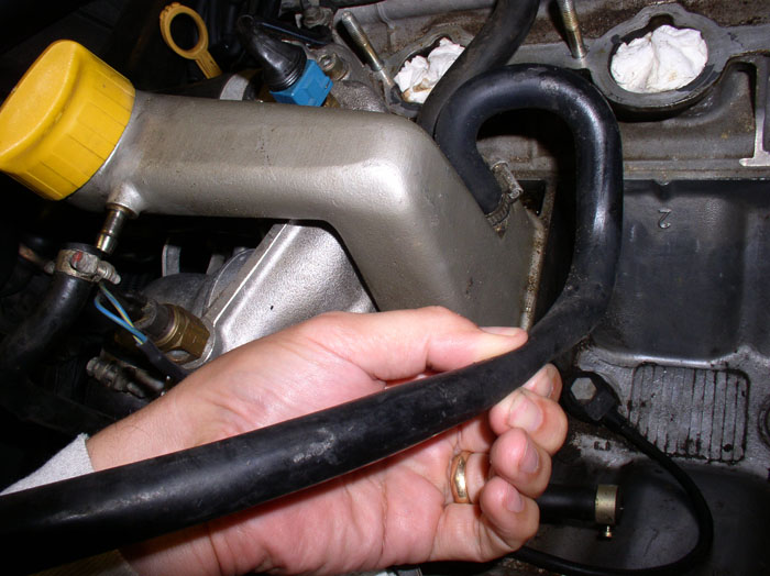
It is not necessary to remove the 3 way hose that leads from the fuel vent solenoid (pictured here) and goes to the oil filler neck and bottom of the throttle body as part of the intake removal. However, I replaced this hose as part of the intake job, so now is a good time to get it out of the way. Loosen the clamp and pull the hose off and remove the 3 way hose .
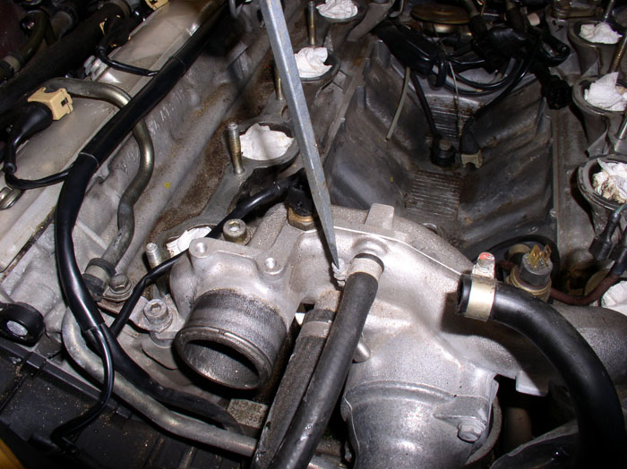
I found it easier to loosen the two 10mm bolts on the thermostat housing elbow while the water bridge as still attached to the heads - for stability. You do not have to remove the elbow, just loosen the bolts.
If you're sending the water bridge in for powder coating or painting, remove the temperature guage sending unit and the Temp II sensor unit from the water bridge now while it's still attached to heads for stability. Use a 19mm deep socket.
continued......
Now, back to the fun!
After you've taken out the flappy plate, pull the flappy spindle out from the bottom of the intake. Keep the spindle, washers and spring intact in a platic baggie. I have pics later of how mine went back together, if needed. You will notice a set of pressed in needle bearings at the top of the intake and at the bottom of the intake. These seem to do alright with age but the seals tend to wear out, dry out, disintegrate. There is a single seal for each bearing (top and bottom). When they no longer seal against the flappy spindle, it can be a source of false air, or vacuum leak. Roger sells new bearng units which have double seals - so twice as many seals as original. We'll be replacing these as well a little later in this post.
Being a newbie, I left the bearings in for the powder coating process not knowing how to take them out. After doing some research on Rennlist, I ran across a post from Shocki where he recommended leaving them in for powder coating so the bearing housing will act as a mask to keep the PC from getting in the bearing seat. Then just plan on replacing the bearings when the intake comes back. I felt much better! THANKS, Shocki!
Now, back to the block. Vacuum the loose debris, if any, and perform any cleaning you might want to do while the old knock sensors are in place. We will be replacing the knock sensors on this job.
With the intake off, now's a good time to look at the hoses and vacuum lines for wear and possible replacement. If you're not planning on simply replacing everything as described early in this post, you'll want to check the hoses for cracks, bulges, soft spots, etc. I checked for softness by pinching them and then bent them like a pretzel to see if any cracks would show up. They all looked pretty good. At first, I thought I would just replace the worn ones. But after I saw the deep impressions the hose clamps made on most of the hoses and also noting that the original hose clamps seem to be designed to have a limit on clamping (i.e., the clamp would easily bottom out and with moderate force, I could twist the hose on some examples), I decided to simply replace all the hoses - so they went on the list.
After inspecting the elbows, I came to the same conclusion. Although the elbows did seem to be in better shape than the hoses, I replaced them anyway. Again, a matter of personal preference.
Removing the oil filler neck and water bridge are not mandatory while removing the intake. However, if you are experiencing leaks or planning on painting/powder coating, they'll have to come off. To remove the oil filler neck, remove the two 10mm bolts that hold the base to the block.
Carefully remove the filler neck from the block ensuring nothing falls into the crankcase. There is a baffle/gasket between the filler neck base and the block. Here it is still attached to the base of the filler neck. On this '87, it is a thin metal plate with an embedded gasket ring. I understand the part is no longer available but we'll talk about this item later.
Directly after removing the filler neck, you can look down into the crankcase for anything unusual. Then stuff it with a clean rag to prevent debris from falling in.
Next, the water bridge. It's a good idea to drain some of the water from the radiator - enough to empty the reservoir - and the block so you don't have too much coolant leaking out when removing the bridge. Since I was also going to be doing the Timing Belt and Water Pump and removing the radiator as part of the job, I emptied all the coolant from the block and the radiator and the reservoir. You can drain the block by locating the drain plugs from underneath the engine. It's a 13mm bolt located toward the rear of the engine. There is one one each side of the block. Place a bucket under the engine at proximity and remove the drain plug. The drain plug comes with a sealing ring. Since these did not look like they have ever been removed, I re-used the sealing ring with no problems. However, if you would like to replace the ring, they can be ordered. When the block is finished draining, you can re-install the drain plugs and torque to 25.8 ftlbs, or 35 Newton meters.
Next, loosen the upper radiator hose clamp using a screwdriver or 10mm socket and remove the hose.
Loosen the bleeder hose clamp with a screwdriver and remove the hose.
Loosen the heater return hose clamp with a screwdriver and remove the hose.
Loosen the lower radiator hose clamp using a screwdriver or 10mm socket and remove the hose.
It is not necessary to remove the 3 way hose that leads from the fuel vent solenoid (pictured here) and goes to the oil filler neck and bottom of the throttle body as part of the intake removal. However, I replaced this hose as part of the intake job, so now is a good time to get it out of the way. Loosen the clamp and pull the hose off and remove the 3 way hose .
I found it easier to loosen the two 10mm bolts on the thermostat housing elbow while the water bridge as still attached to the heads - for stability. You do not have to remove the elbow, just loosen the bolts.
If you're sending the water bridge in for powder coating or painting, remove the temperature guage sending unit and the Temp II sensor unit from the water bridge now while it's still attached to heads for stability. Use a 19mm deep socket.
continued......
01-17-2009, 11:17 PM
#29
Rennlist Member
Join Date: Oct 2005
Location: Gatineau, Qu�bec, Canada
Posts: 5,168
Received 1,289 Likes
on
490 Posts
Thank you very much for this very good (as always) write-up procedure.
You, and only you, can do such a perfect job.
You are the best.
I read the entire thread tonight (alone at home without the children and wife...) and learn in 2 hours exactly what I need to do next spring.
I will use M. Chamberland (witch I did not read yet) AND YOUR'S FOR SURE.
Thank you again and keep writing such wonderful write-up procedures.
It's because of guys like you here on Rennlist that I can own and maintain such a wonderful car as the Porsche 928. My dream car forever... With a few more if I would have more $$$$$$...
Many thanks again.
Last edited by Bertrand Daoust; 01-17-2009 at 11:35 PM.
01-17-2009, 11:35 PM
#30
Three Wheelin'
Thread Starter
Join Date: Sep 2007
Location: Ridgecrest, California
Posts: 1,363
Likes: 0
Received 146 Likes
on
30 Posts
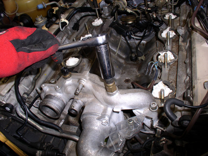
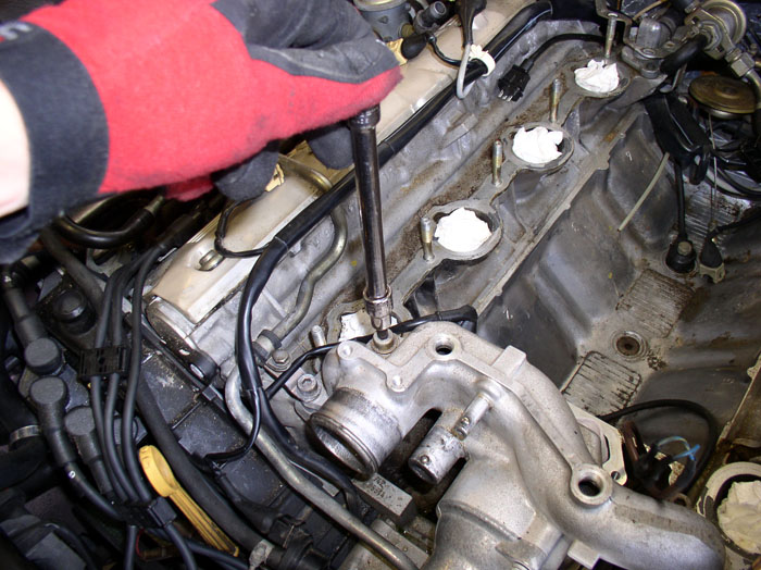
Now you can remove the 6mm allen head bolts that secure the bridge to the heads. You will find one of the bolts is longer than the others. The bolt pictured here under the socket, is 70mm in length while the other 3 are 35mm in length.
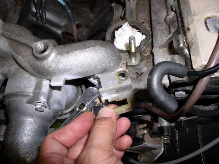
Remember to include the the fuel line bracket in the baggie with the water bridge bolts.....
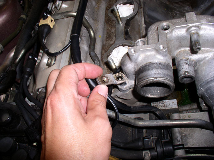
...as well as the knock sensor bracket on the driver's side. Also included with the bracket is a metal clip - barely visible in this picture, next to my index finger - that holds the sensor in the bracket.
Now you can remove the water bridge from the block.
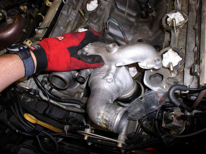
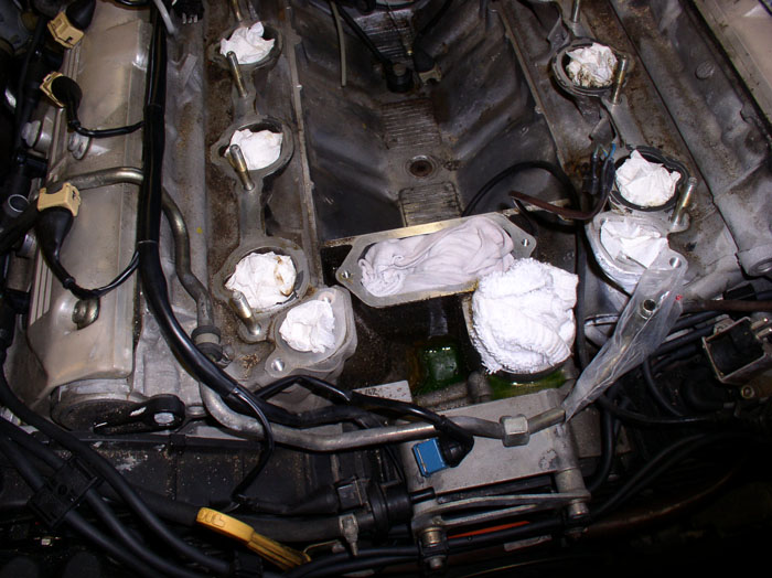
And immediately stuff the hole with a clean rag to prevent debris from entering the water pump.
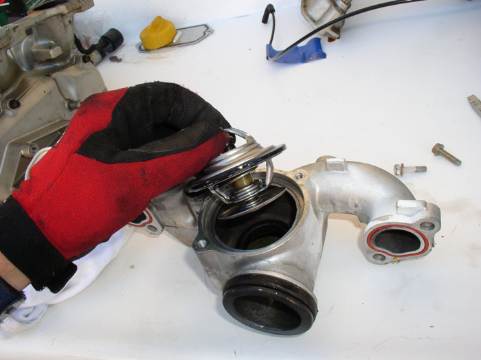
Next, I disassembled the waterbridge in preparation for powder coating. After removing the previously loosend 10mm thermostat elbow bolts, remove the elbow and pull out the thermostat and o-ring.
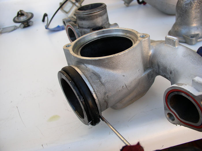
Then remove the bridge to block o-ring at the bottom of the bridge. I used a pick tool to get under the o-ring and pull it over the bridge flange. Also, remove the red bridge to heads gaskets (one on each side).
Lastly, remove the rear thermostat seal. I found a screwdriver and hammer to work well and removing the seal. Be careful not to mar the mating surface of the housing. Place the screwdriver, oriented as in the picture, against the seal and tap with a hammer to distort the seal as pictured. Then use a pair of pliers to pull out the seal. Now the waterbridge is ready for powder coating.
continued.....
Remember to include the the fuel line bracket in the baggie with the water bridge bolts.....
...as well as the knock sensor bracket on the driver's side. Also included with the bracket is a metal clip - barely visible in this picture, next to my index finger - that holds the sensor in the bracket.
Now you can remove the water bridge from the block.
And immediately stuff the hole with a clean rag to prevent debris from entering the water pump.
Next, I disassembled the waterbridge in preparation for powder coating. After removing the previously loosend 10mm thermostat elbow bolts, remove the elbow and pull out the thermostat and o-ring.
Then remove the bridge to block o-ring at the bottom of the bridge. I used a pick tool to get under the o-ring and pull it over the bridge flange. Also, remove the red bridge to heads gaskets (one on each side).
Lastly, remove the rear thermostat seal. I found a screwdriver and hammer to work well and removing the seal. Be careful not to mar the mating surface of the housing. Place the screwdriver, oriented as in the picture, against the seal and tap with a hammer to distort the seal as pictured. Then use a pair of pliers to pull out the seal. Now the waterbridge is ready for powder coating.
continued.....