
'87 Intake Removal, Repairs, Installation Procedure (w/pics)
 01-24-2009, 09:01 PM
#91
Addict
Lifetime Rennlist
Member
Lifetime Rennlist
Member
you can order the gauge on line...I googled the part number and brand from the picture he posted. i found mine locally at HD.
the regulator was off the leak down tester i have...i hooked that to my air line...then hooked to that a tire inflater whose end can be secured to the schrader valve without you having to hold it....I zipped tied the trigger ON.
Really high tech ya know!
Hooked it up...then went around the engine with a piece of small pipe listening for leaks.
Only thing i was leary off were some of the regulators and dampers and tranny module seeing POSITVE pressure. I would recommend that those lines be pulled and capped for the test perhaps?
 01-24-2009, 10:41 PM
#92
Three Wheelin'
Thread Starter
Join Date: Sep 2007
Location: Ridgecrest, California
Posts: 1,363
Likes: 0
Received 146 Likes
on
30 Posts
Dwayne & Tony,
I have been asked to put together a test kit for those overseas who do not have the luxury of a Home Depot or for those who are challenged with shopping 8>)
Found everything at HD apart from the gauge and fitting - maybe not available in Texas.
Can you be more specific with name and part number or a squew (spelling) number?.....
Outstanding Idea making the kits! I tried to find my old receipt in case it had a SKU but couldn't find it. However, from the package it came in
MFR is Danco
Name is "Gas Test Gauge, 0-15 PSI"
Part no. is 94352
Barcode from package is 037155943524
I will stop by HD tomorrow and ask about availability at other HD's and see if I can get a SKU for you. Let me know if you need any other information.
01-24-2009, 10:51 PM
#94
Three Wheelin'
Thread Starter
Join Date: Sep 2007
Location: Ridgecrest, California
Posts: 1,363
Likes: 0
Received 146 Likes
on
30 Posts
Built one yesterday...this should be on everyones list. works well.
Ive got a very small leak as far as i can tell. i used soapy water around some areas and got it to bubble at the front where my SC mates to the manfiold. Prety minor and im notgoing to mess with it until i take it off again later for some other reason.
I would like to be able to have smoke pass though the intake system and then it would be easier to see exactly where leaks are occuring. Any one done that?
thanks again for the write up and showing the device you made.
Also...i added a regulator to the line that feeds the schraeder valve on the tester..i set it for about 4 psi....this way ,if there was a leak it would continue to pressurize the intake system while I looked around for it. Opposed to pressurizing it , then having it leak out right away....then having to pressureize again....over an over.
Hi Tony,
Great idea on the regulator! Wish I thought of that! You're right, I would find myself pressurizing the system over and over while I was searching for the leak. A regulator could have kept constant pressure going. I'll have to see if I can find a low pressure regulator and rig something up next time I do an intake leak test.
As far as the smoke tester. Yes, I tried to make a home brew version using a 1 gallon metal paint can and portable electric stove top burner and the air compressor. Took pictures of the design and build process. Worked pretty good a couple of times. I found it difficult to secure the lid so a few times it blew off and the oil in the paint can immediately burst into flames - EXCITING! I should have taken pictures of THAT! Anyway, I gave up on building a smoke tester, for now.
 01-24-2009, 11:13 PM
#95
Basic Sponsor
Rennlist
Site Sponsor
Rennlist
Site Sponsor
Hi Tony,
I wish it was that easy.
Only one place on line recognized the number or the manufacturer.
I was hoping it was available for everyone at HD. Not so it would appear.
Luckily we have two very senior HD local 928 owners who may help out.
Dwayne,
Thanks for the help it would be really usefull to know if it is a regional product.
I was hoping to find the manufacturer and buy in quantity.
Roger
__________________

Does it have the "Do It Yourself" manual transmission, or the superior "Fully Equipped by Porsche" Automatic Transmission? George Layton March 2014
928 Owners are ".....a secret sect of quietly assured Porsche pragmatists who in near anonymity appreciate the prodigious, easy going prowess of the 928."
Does it have the "Do It Yourself" manual transmission, or the superior "Fully Equipped by Porsche" Automatic Transmission?
George Layton March 2014928 Owners are ".....a secret sect of quietly assured Porsche pragmatists who in near anonymity appreciate the prodigious, easy going prowess of the 928."
01-25-2009, 01:42 AM
#96
Rennlist Member
Join Date: Dec 2002
Posts: 1,051
Likes: 0
Received 0 Likes
on
0 Posts
Dwayne,
Several things in your pictures indicate that your engine is an earlier '87 one. In post #11 you showed a picture of the failed fuel rail mounts, and mentioned that they'll be replaced. I don't know if those type of mounts with the rubber section in them are still being sold for that application, but if they are, I'd say not to use them. As you saw, the rubber fails. I've heard that those types of mounts failing like that were the cause of some engine fires in '87 model year cars that had them.
Porsche made a change to the fuel rail mounting, and did away with the mounts having that rubber section. The later '87 cars that I've seen used plain studs in the intake manifold, with aluminum spacers of the same thickness as the rubber section of the old type mounts slipped over the studs. The fuel rails are then installed as normal, tightening them down against the aluminum spacers. For later cars yet, the design was changed so that the aluminum spacers were no longer needed. The "legs" of the later fuel rails were made longer, and the fuel rails just went directly over plain studs sticking up from the intake manifold.
I don't know if Porsche shows a part number for the aluminum spacers that would go over plain studs for your engine or not, but washers stacked to the same height as the rubber section of your original mounts could be used as well.
01-25-2009, 08:25 AM
#97
Addict
Lifetime Rennlist
Member
Lifetime Rennlist
Member
Hi Tony,
I wish it was that easy.
Only one place on line recognized the number or the manufacturer.
I was hoping it was available for everyone at HD. Not so it would appear.
Luckily we have two very senior HD local 928 owners who may help out.
Dwayne,
Thanks for the help it would be really usefull to know if it is a regional product.
I was hoping to find the manufacturer and buy in quantity.
Roger
I wish it was that easy.
Only one place on line recognized the number or the manufacturer.
I was hoping it was available for everyone at HD. Not so it would appear.
Luckily we have two very senior HD local 928 owners who may help out.
Dwayne,
Thanks for the help it would be really usefull to know if it is a regional product.
I was hoping to find the manufacturer and buy in quantity.
Roger
If you google ''Gas Test Gauge 15 psi'' you'll find more, but different manufacturers. For example this one http://www.plumbersurplus.com/Prod/W.../12475/Cat/888
01-25-2009, 12:40 PM
#98
Three Wheelin'
Thread Starter
Join Date: Sep 2007
Location: Ridgecrest, California
Posts: 1,363
Likes: 0
Received 146 Likes
on
30 Posts
Hi Tony,
I wish it was that easy.
Only one place on line recognized the number or the manufacturer.
I was hoping it was available for everyone at HD. Not so it would appear.
Luckily we have two very senior HD local 928 owners who may help out.
Dwayne,
Thanks for the help it would be really usefull to know if it is a regional product.
I was hoping to find the manufacturer and buy in quantity.
Roger
I wish it was that easy.
Only one place on line recognized the number or the manufacturer.
I was hoping it was available for everyone at HD. Not so it would appear.
Luckily we have two very senior HD local 928 owners who may help out.
Dwayne,
Thanks for the help it would be really usefull to know if it is a regional product.
I was hoping to find the manufacturer and buy in quantity.
Roger
Just got back from HD. The SKU is 459-718. I asked the manager if they were at all HDs. He said it should be. I asked it he could check to see if they carry it at a HD close to Double Oak, TX (e.g., Flower Mound). He logged in and checked the store. The SKU is active for the store but shows 0 inventory. I asked what that meant. He said it could mean that store doesn't stock it or may be out of inventory. You could give the manager the SKU and he could tell you if he could order it.
However, since you're interested in conctacting the MFR for a quantity buy. Here's some more information that may be helpful. I bought another unit this morning.
The unit is sold/packaged by Danco Company. Their website is at www.danco.com. Corpporate office is at 2727 Chemsearch Blvd, Iving, TX 75082 (1-800-523-5135). The Danco part numbers appears to be 94352. Danco Company is a division of Plumbmaster, Inc. in Concordville, PA 19331. Plumbmaster has a website at www.plumbmaster.com. Phone 1-800-523-5130. Hope this helps. Let me know if you need anything else. There are 7 units on the shelf here - let me know if you want some quick and I'll send them to you - HD sells them for only $9.87 each.
01-25-2009, 04:42 PM
#99
Basic Sponsor
Rennlist
Site Sponsor
Rennlist
Site Sponsor
Dwayne,
The SKU is what I needed - thanks.
I found both Danco and plumbmaster sites but no specific info on the gauge.
As they are here in Texas that makes it easier.
I will call them tomorrow and see what they do for wholesale.
Best,
Roger
The SKU is what I needed - thanks.
I found both Danco and plumbmaster sites but no specific info on the gauge.
As they are here in Texas that makes it easier.
I will call them tomorrow and see what they do for wholesale.
Best,
Roger
01-25-2009, 04:58 PM
#100
Archive Gatekeeper
Rennlist Member
Rennlist Member
Mini hijack-
Roger, while you're souricing parts, can you find these bearings?
I pulled the throttle quadrant apart this morning and found 6 (!) HK0810RS bearings- 3 pairs in each of the linkage pieces:

'Scuse the crappy pic, it shoes the bearings doubled up in the bore:

Bearing ID:

Dwayne- we'll have to figure out what diameter all-thread works for installation on these....
Roger, while you're souricing parts, can you find these bearings?
I pulled the throttle quadrant apart this morning and found 6 (!) HK0810RS bearings- 3 pairs in each of the linkage pieces:
'Scuse the crappy pic, it shoes the bearings doubled up in the bore:
Bearing ID:
Dwayne- we'll have to figure out what diameter all-thread works for installation on these....
01-25-2009, 08:21 PM
#102
Three Wheelin'
Thread Starter
Join Date: Sep 2007
Location: Ridgecrest, California
Posts: 1,363
Likes: 0
Received 146 Likes
on
30 Posts
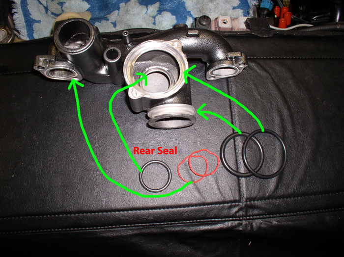
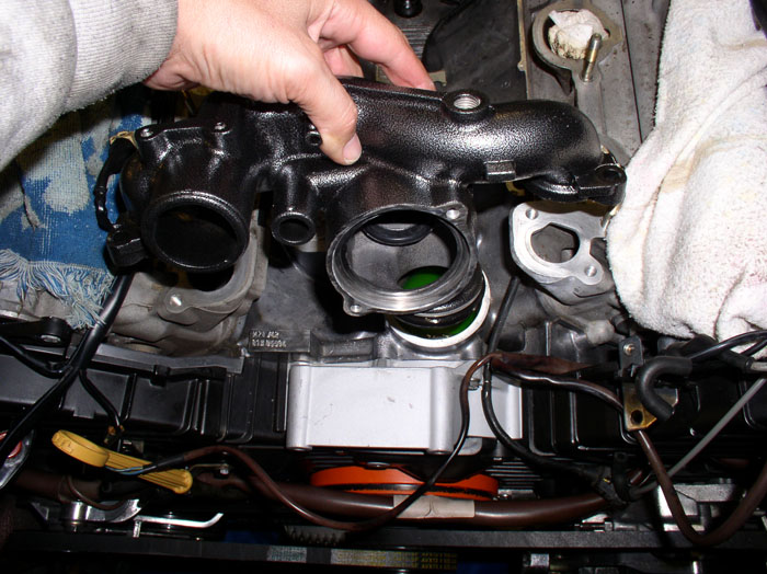
OK....back to the installation. Next, I prepared the water bridge and oil filler neck for re-installation. First the water bridge. It's a good idea to replace all the o-rings and seals. Here's a pic of the bridge and the seals that need to be installed. There are two red seals for the bridge to cylinder heads. A thermostat rear seal that mounts to the rear of the bridge. A thick o-ring that is installed at the base of the bridge for the bridge to block connection. And finally, the thermostat o-ring for the 90 degree elbow pipe.
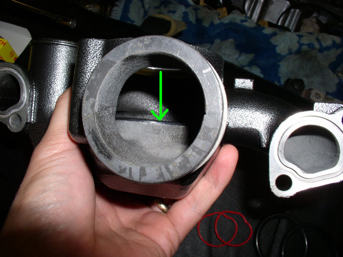
First, install the rear seal. Simply press it into place as shown.

Ensure it is fully seated. The lip should lay flat on the thermostat housing as shown.
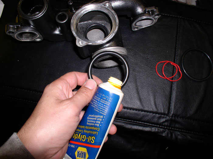
Next, the bridge to block o-ring. I applied a thin coat of silicone lubricant to the o-ring to help get the ring on the bridge but also to help install the bridge into the block.
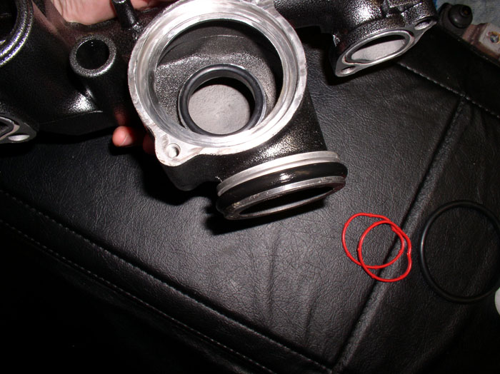
The mounted o-ring should look like this.
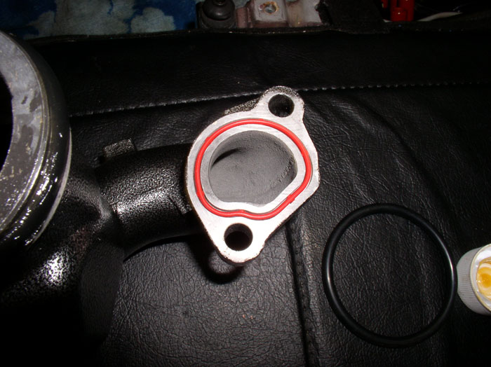
Next came the bridge-to-cylinder heads seals. There are two of these and they are moulded to the contour of the bridge port. Insert the seal into the grooves matching the moulding to the grooves in the port.
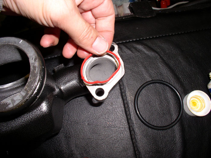
You will notice small ***** that protrude from the seal that help hold the seal in place during installation. Installed seal should look like this.
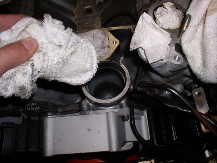
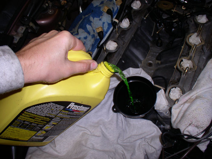
Now it's time to fill the block with coolant. I usually simply install the bridge with the block empy of coolant. Being adventurous, I decided to fill the block first to aid in bleeding air in the system when re-filling the coolant. I found this method to work much better at getting air out of the system than my previous method. Remove the rag protecting the thermostat bridge port to the block and instert a funnel. Also, remove the stuffing from the cylinder heads coolant ports and ensure the mating surfaces are clean if you haven't already cleaned them.
It's best to use distilled water mixed with your coolant. Continuing to feel adventurous, I used a 70% water and 30% coolant mixture this time. Previous times I always used 50/50 mix.
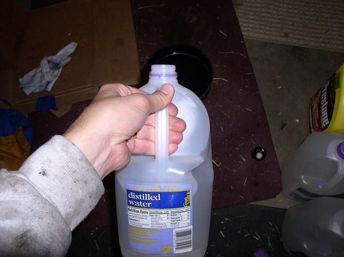
Add coolant until you see it pool at the base of the thermostat bridge port in the block.
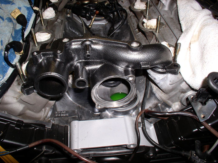
Next, Position the bridge and line up the bridge-to-block o-ring.
Press the bridge down from on top until it is fully seated. The cylinder head ports on each side will seat first.
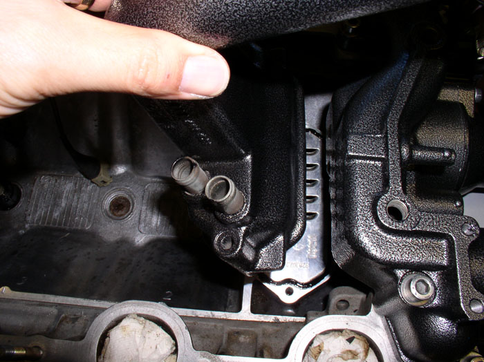
Install the 6mm allen head bolts. There are four of them. The long one goes on the passenger side to the rear. Make sure you also install the fuel line clamp bracket on the forward passenger side 6mm allen head bolt. Before installing the driver's side front bolt, you will need to install the Fuel Pressure Damper (FPD).
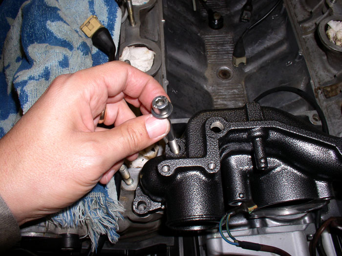
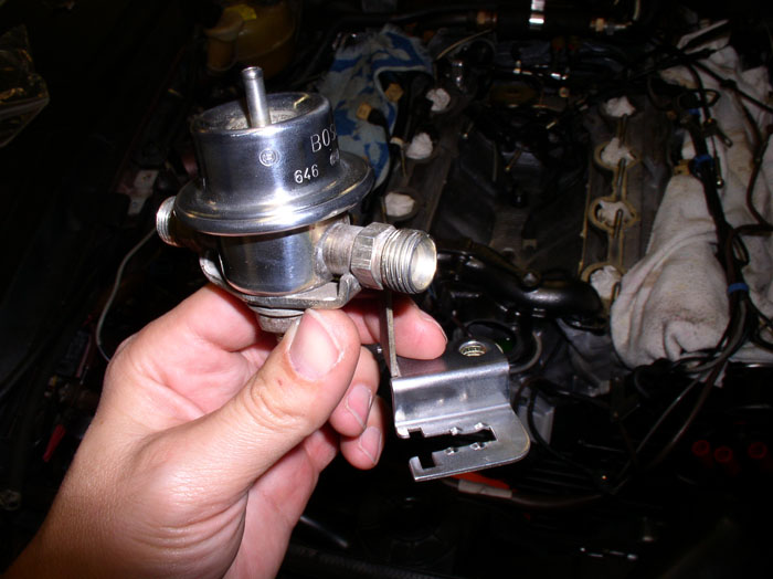
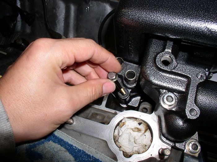
The FPD has an "L" bracket attached that holds the front knock sensor connector to the wiring harness. See below.
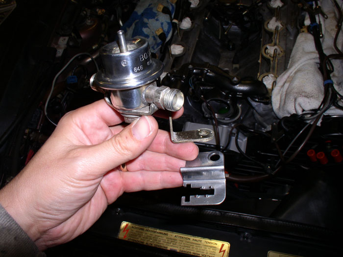
Install the knock sensor bracket on top of the "L" of the FPD as shown.
continued.....
First, install the rear seal. Simply press it into place as shown.
Ensure it is fully seated. The lip should lay flat on the thermostat housing as shown.
Next, the bridge to block o-ring. I applied a thin coat of silicone lubricant to the o-ring to help get the ring on the bridge but also to help install the bridge into the block.
The mounted o-ring should look like this.
Next came the bridge-to-cylinder heads seals. There are two of these and they are moulded to the contour of the bridge port. Insert the seal into the grooves matching the moulding to the grooves in the port.
You will notice small ***** that protrude from the seal that help hold the seal in place during installation. Installed seal should look like this.
Now it's time to fill the block with coolant. I usually simply install the bridge with the block empy of coolant. Being adventurous, I decided to fill the block first to aid in bleeding air in the system when re-filling the coolant. I found this method to work much better at getting air out of the system than my previous method. Remove the rag protecting the thermostat bridge port to the block and instert a funnel. Also, remove the stuffing from the cylinder heads coolant ports and ensure the mating surfaces are clean if you haven't already cleaned them.
It's best to use distilled water mixed with your coolant. Continuing to feel adventurous, I used a 70% water and 30% coolant mixture this time. Previous times I always used 50/50 mix.
Add coolant until you see it pool at the base of the thermostat bridge port in the block.
Next, Position the bridge and line up the bridge-to-block o-ring.
Press the bridge down from on top until it is fully seated. The cylinder head ports on each side will seat first.
Install the 6mm allen head bolts. There are four of them. The long one goes on the passenger side to the rear. Make sure you also install the fuel line clamp bracket on the forward passenger side 6mm allen head bolt. Before installing the driver's side front bolt, you will need to install the Fuel Pressure Damper (FPD).
The FPD has an "L" bracket attached that holds the front knock sensor connector to the wiring harness. See below.
Install the knock sensor bracket on top of the "L" of the FPD as shown.
continued.....
Last edited by Dwayne; 01-25-2009 at 09:02 PM.
01-25-2009, 09:00 PM
#103
Three Wheelin'
Thread Starter
Join Date: Sep 2007
Location: Ridgecrest, California
Posts: 1,363
Likes: 0
Received 146 Likes
on
30 Posts
Install the Fuel Pressure Damper (FPD) on top of the driver's side front mounting hole and install the allen head bolt. Also install the fuel line clamp bracket on the passenger side front of the bridge and install the allen head bolt as shown. I simply finger tightened the bolts down for now.
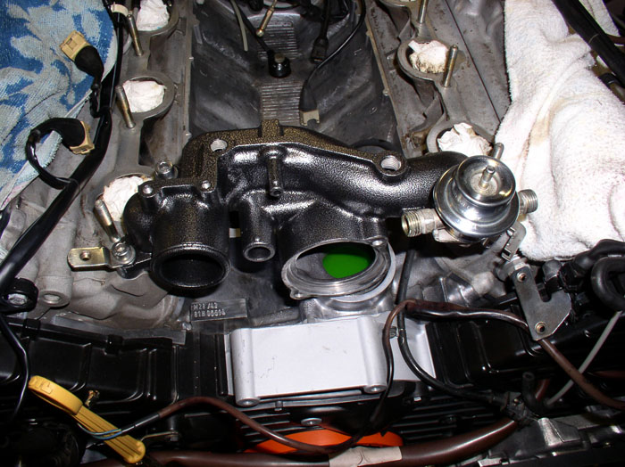
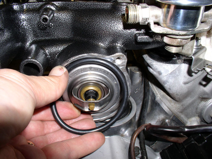
Next, install the thermostat. You will notice an arrow stamped on the front of the thermostat flange. Position this arrow so that it is facing up and mount the thermostat into its groove in the thermostat housing. You will notice a shallow inner groove in the housing - use this for the thermostat.
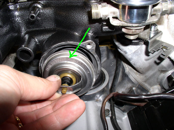
Place the o-ring over the thermostat as shown. It should fit inside the outer groove as shown.
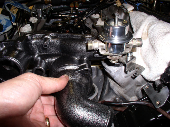
Place the 90 degree elbow into position lining up the bolt mounting holes.
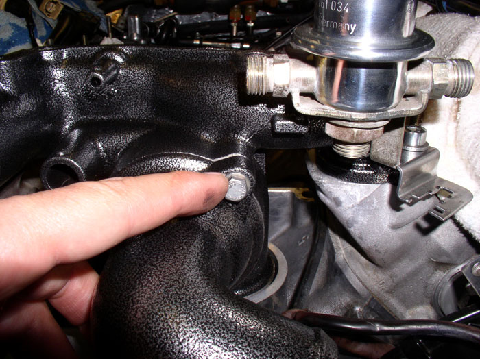
Install the two 10mm housing bolts and finger tighten.
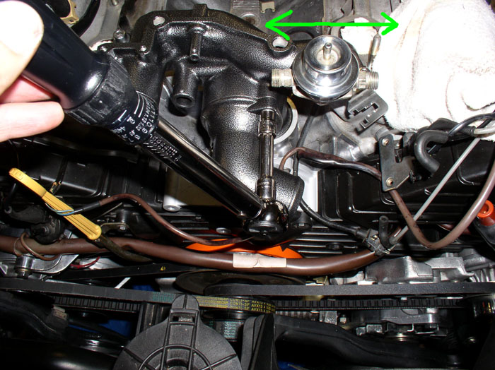
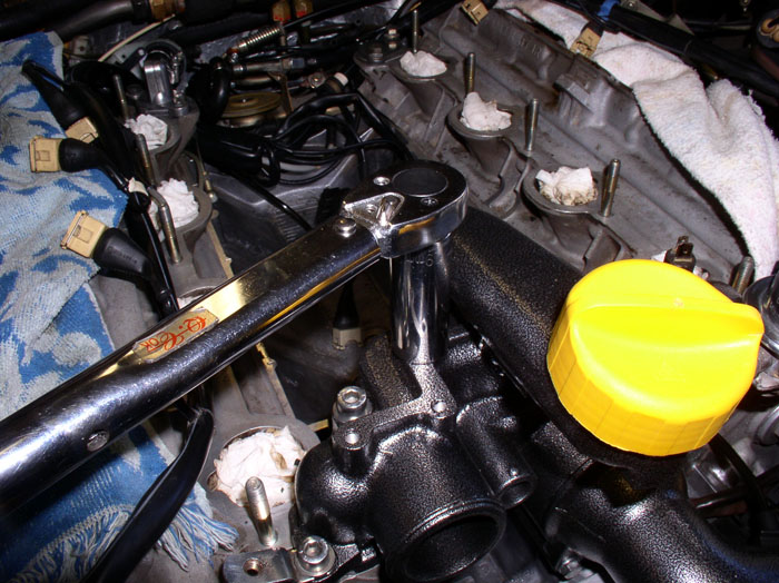
Now, you can torque everything down. First, ensure the FPD is aligned so that it runs parallel with the engine brace (approximately) as shown in the pic below. The WSM recommends a two pass torque method on the Bridge-to-cylinder heads 6mm allen head bolts. First pass, torque the allen head bolts to 7 ftlbs or 84 inch lbs. Second pass, tighten the allen head bolts to 16 flt lbs or 192 inch lbs. Then torque the 90 degree elbow into place with the two 10mm bolts. Torque to 8 ftlbs or 96 inch lbs.
Next came the oil filler neck. My filler neck is metal and has the metal baffle with integrated rubber seal. The seal had hardened and was no longer providing a good seal. I understand this part is no longer available. So I decided to improvise and use gasket maker/sealer on the existing seal. If you have the plastic baffle, seals are separate and still available. You can install the new seal at this time.
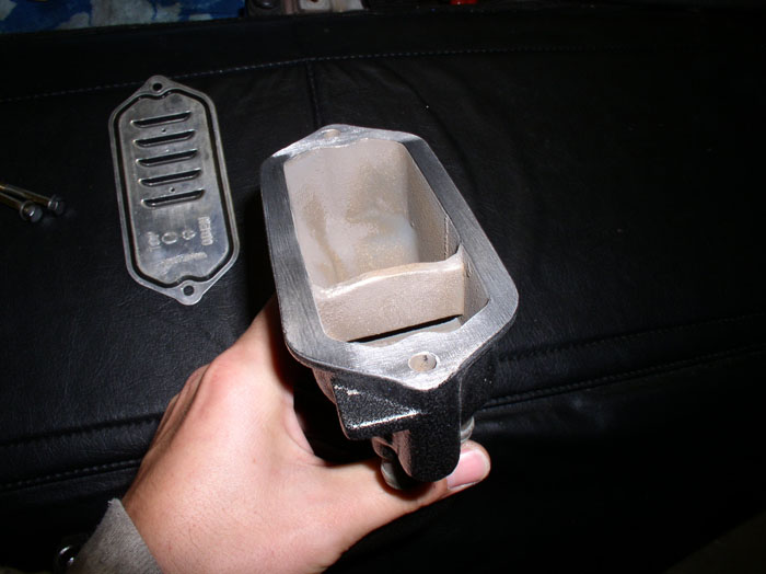
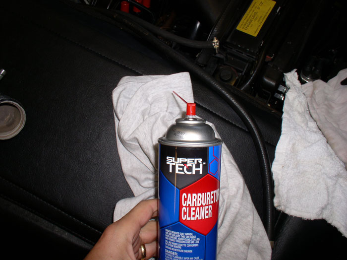
Otherwise, if you're in the same boat as I am, picking a sealant suited for the job is next. This seems like appropriate sealant to use. From the package, it advertises it's very resistant to oil and is sensor safe.

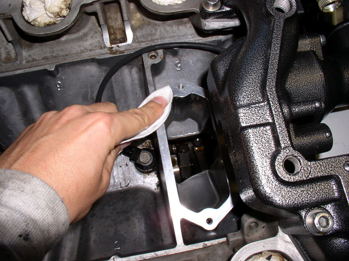
First, you will need to clean the mating surface for the sealant. I used brake cleaner sprayed on a cloth.....
....then wipe the cloth on the block surface and the oil filler neck mating surface to remove any dirt or oily residue.
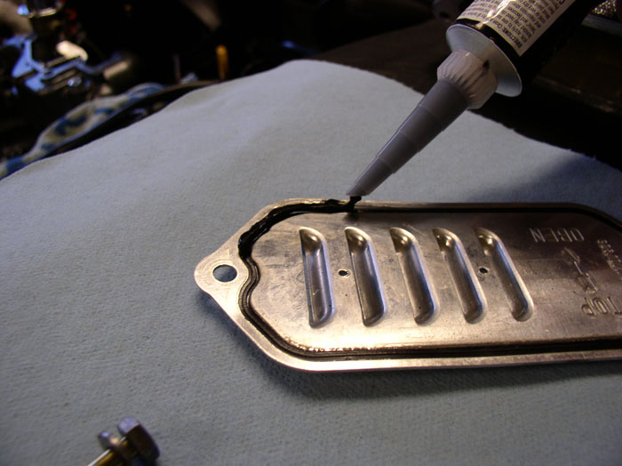
Apply a small bead of sealant/gasket maker to the existing seal. Apply to both sides.
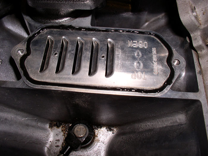
Position the baffle with sealant into position making sure it is oriented properly.
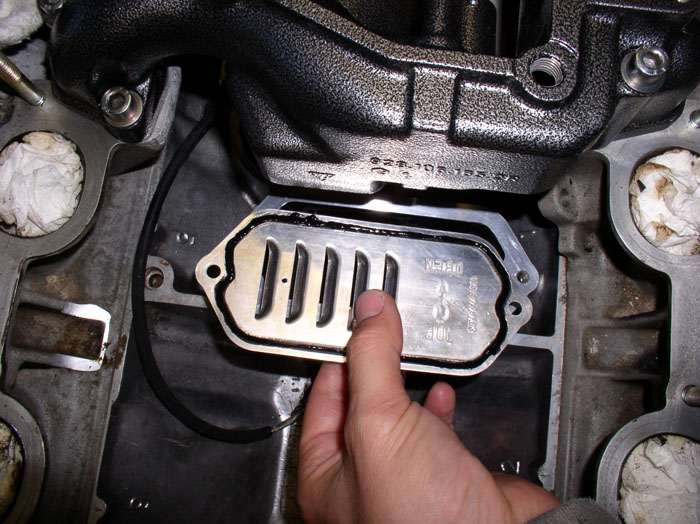
Note the markings on the baffle. There is the word "TOP", "OBEN" and an arrow stamped into the surface. I oriented my baffle so "TOP" is facing up and the arrow is pointing forward out the front of the car as shown.
Next, position the oil filler neck over the top of the baffle, line up the mounting holes and set it into place.
Install the two 10mm bolts and finger tighten.
continued.....
Next, install the thermostat. You will notice an arrow stamped on the front of the thermostat flange. Position this arrow so that it is facing up and mount the thermostat into its groove in the thermostat housing. You will notice a shallow inner groove in the housing - use this for the thermostat.
Place the o-ring over the thermostat as shown. It should fit inside the outer groove as shown.
Place the 90 degree elbow into position lining up the bolt mounting holes.
Install the two 10mm housing bolts and finger tighten.
Now, you can torque everything down. First, ensure the FPD is aligned so that it runs parallel with the engine brace (approximately) as shown in the pic below. The WSM recommends a two pass torque method on the Bridge-to-cylinder heads 6mm allen head bolts. First pass, torque the allen head bolts to 7 ftlbs or 84 inch lbs. Second pass, tighten the allen head bolts to 16 flt lbs or 192 inch lbs. Then torque the 90 degree elbow into place with the two 10mm bolts. Torque to 8 ftlbs or 96 inch lbs.
Next came the oil filler neck. My filler neck is metal and has the metal baffle with integrated rubber seal. The seal had hardened and was no longer providing a good seal. I understand this part is no longer available. So I decided to improvise and use gasket maker/sealer on the existing seal. If you have the plastic baffle, seals are separate and still available. You can install the new seal at this time.
Otherwise, if you're in the same boat as I am, picking a sealant suited for the job is next. This seems like appropriate sealant to use. From the package, it advertises it's very resistant to oil and is sensor safe.
First, you will need to clean the mating surface for the sealant. I used brake cleaner sprayed on a cloth.....
....then wipe the cloth on the block surface and the oil filler neck mating surface to remove any dirt or oily residue.
Apply a small bead of sealant/gasket maker to the existing seal. Apply to both sides.
Position the baffle with sealant into position making sure it is oriented properly.
Note the markings on the baffle. There is the word "TOP", "OBEN" and an arrow stamped into the surface. I oriented my baffle so "TOP" is facing up and the arrow is pointing forward out the front of the car as shown.
Next, position the oil filler neck over the top of the baffle, line up the mounting holes and set it into place.
Install the two 10mm bolts and finger tighten.
continued.....
01-25-2009, 09:15 PM
#104
Three Wheelin'
Thread Starter
Join Date: Sep 2007
Location: Ridgecrest, California
Posts: 1,363
Likes: 0
Received 146 Likes
on
30 Posts
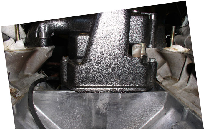
Next, torque the two 10mm oil filler neck mounting bolts down. Torque to 8 ftlbs or 96 inch lbs.
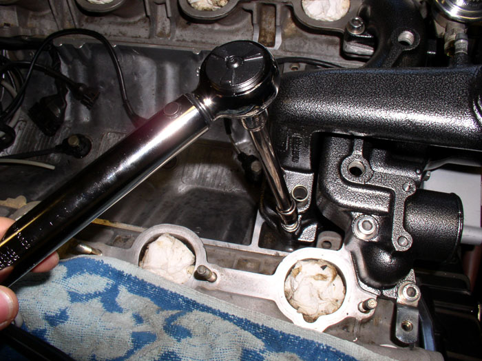
Ideally, you want a consistent showing of sealant as evidence of a good seal with sufficient sealant all around but you don't want an excessive amount showing - just enough to be barely visible.
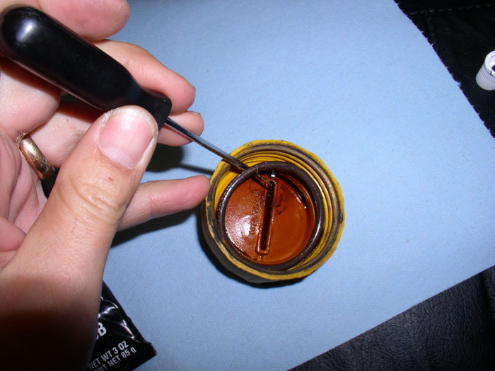
Next, the finishing touch on the oil filler neck - Replacing the o-ring in the filler cap. Remove the old o-ring with a pick tool. You can clean the cap (especially the outside of it) with your favorite cleaner (Orange Blast citrus cleaner in my case). I've also heard that comet cleanser works but have not tried that yet.
Install the new o-ring with some motor oil on it to ease installation of the o-ring but also to provide a lubricated surface to mate with the filler neck.
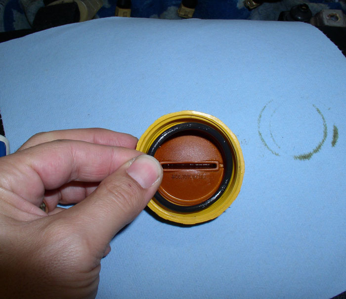
Install the cap on the filler neck.
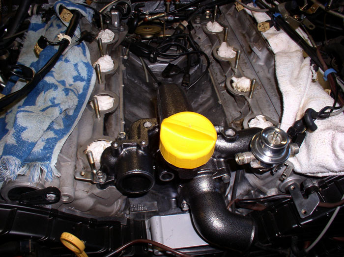
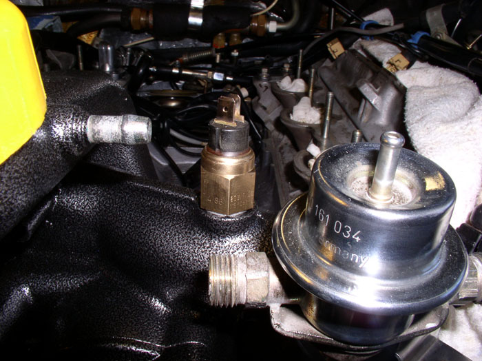
Finally, finish off the water bridge. Install the Temperature Gauge sending unit with sealing ring. It is mounted on top of the bridge on the driver's side. It's best to use a new sealing ring but the old one can be re-used if not worn out. Finger tighten down.
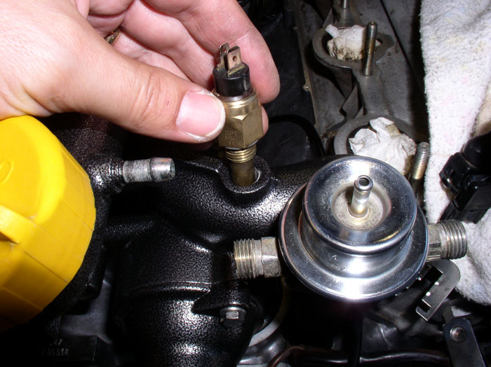
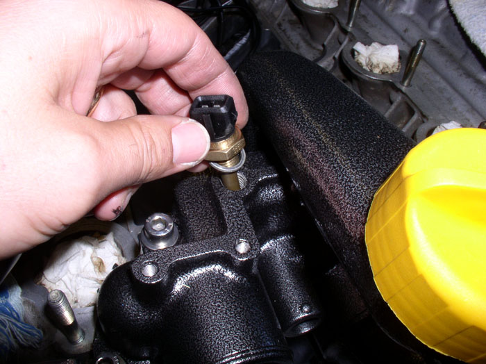
Install the Temp II sensor in the same manner on the other side of the bridge..
Torque the Temp II sensor to 9 ftlbs or 108 inch lbs. Torque the temperature gauge sending unit to 20 ftlbs.
Temp II sensor installed with seal.
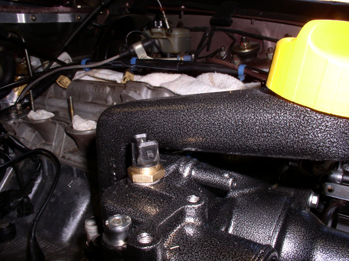
Temp gauge sending unit installed with seal.
continued.....
Ideally, you want a consistent showing of sealant as evidence of a good seal with sufficient sealant all around but you don't want an excessive amount showing - just enough to be barely visible.
Next, the finishing touch on the oil filler neck - Replacing the o-ring in the filler cap. Remove the old o-ring with a pick tool. You can clean the cap (especially the outside of it) with your favorite cleaner (Orange Blast citrus cleaner in my case). I've also heard that comet cleanser works but have not tried that yet.
Install the new o-ring with some motor oil on it to ease installation of the o-ring but also to provide a lubricated surface to mate with the filler neck.
Install the cap on the filler neck.
Finally, finish off the water bridge. Install the Temperature Gauge sending unit with sealing ring. It is mounted on top of the bridge on the driver's side. It's best to use a new sealing ring but the old one can be re-used if not worn out. Finger tighten down.
Install the Temp II sensor in the same manner on the other side of the bridge..
Torque the Temp II sensor to 9 ftlbs or 108 inch lbs. Torque the temperature gauge sending unit to 20 ftlbs.
Temp II sensor installed with seal.
Temp gauge sending unit installed with seal.
continued.....
Last edited by Dwayne; 01-25-2009 at 09:30 PM.