
'87 Intake Removal, Repairs, Installation Procedure (w/pics)
 02-08-2009, 06:10 PM
#151
Three Wheelin'
Thread Starter
Join Date: Sep 2007
Location: Ridgecrest, California
Posts: 1,363
Likes: 0
Received 146 Likes
on
30 Posts
If you removed the hood, now's the time to re-install it. First, lubricate the hinge joints. I used a light general purpose oil. Work the hinges up and down several times to work in the oil.
If you're working alone, like me, lay out your bolts and shims and wrenches so they are easily accessable near the hinges. I had two shims for each side.
Place a towel under the hood near the hinge and cowl to protect it from scratches. I also left the service covers on for fender protection. Bring the hood over and gently lay it into position as shown.
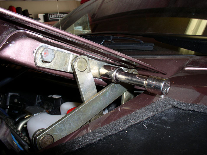
Next, lift up one side of the hood at the hinge and insert the shims. Line up the holes for the front bolt and install the 13mm bolt - I used the 13mm socket and 3" extension bar. Do the same for the other side of the hood.
I then lifted the hood with one hand and used the other to start the rear bolt using the extension again. The objective is to simply get the bolt well started in the hole. Do the same for the other side of the hood.
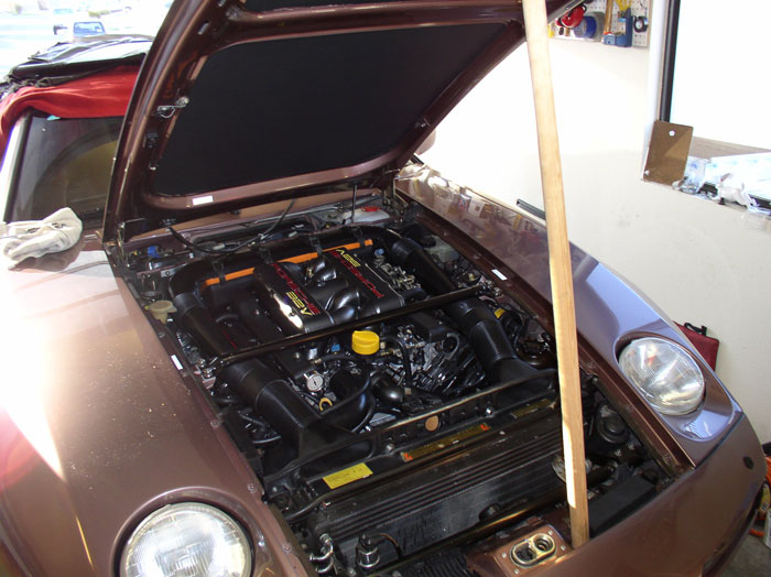
Next, support the hood with a wooden or rubber tipped rod. I used a clothes hangar dowel you find in your closet. Remove the service covers at this time so you can check for proper alignment.
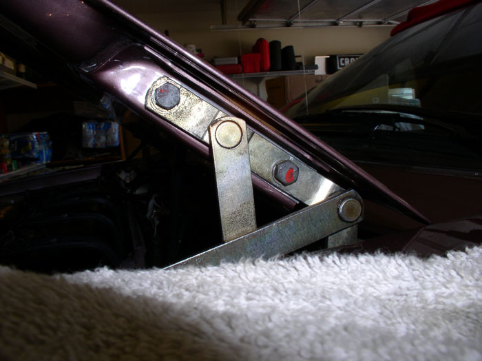
Now you can fine tune the adjustment. First position the hinge so that it is approximately where it was when you removed it. I was carefull not to wash or wax the area at the hinge since the original 'dirt' left a marker where the hinge should go.
When it's lined up as close as you can get it to it original position, snug all four of the bolts down LIGHTLY - just enough to hold them in place as you make final adjustments.
Move to the front of the hood and check the alignment of the hood pin to the receiver latch. It should be perfectly centered in the hole. Mine was very close on first try but I had to fine tune it. Do not try to latch the hood (i.e., press it all the way down into the receiver) unless it looks perfectly centered - otherwise it can get wedged in there and be difficult to "unlatch". If it's not lined up perfectly, raise and support the hood enough to gain access to the bolts at the hinges and loosen enough to adjust the hood slightly. For example, when looking at the hood from the front of the car, my hood pin was a little to the left of the center of the receiver hole. I loosened the passenger side bolts at the hinge and moved the hood forward about 1/16 of an inch then snugged the bolts down again. Then go to the pin and receiver at the front and check alignment again. It took me two adjustments to get it centered. It's trial and error mixed with a little patience and you can get it perfect. When it's aligned in the center of the receiver, close the hood all the way and try opening it from the hood release lever in the car to check for normal operation. I have found this method also ensures the gaps between the hood and fender consistenly come out even as well. The final adjustment check to make is hood height. It should be flush with the fenders. If it's too high or low, you will need to make an adjustment at the hinge again. This time, when you loosen the bolts, simply raise or lower the hood a the hinge to get the right height - trick is to keep the bolts snug enough that you can move the hood at the hinge without allowing it to slip forward or back. After the height adjustment, check for normal operation again.
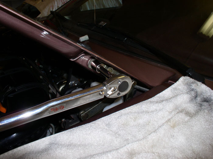
When the hood operation checks out, torque the 13mm hood bolts to 15 ftlbs.
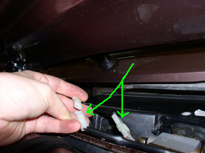
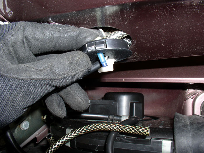
Next, make the electrical connections. There should be a 2 pin connector and a 3 pin connector to the hood. These are for the heated windshield washer nozzles and hood light. Make both of these connections as shown.
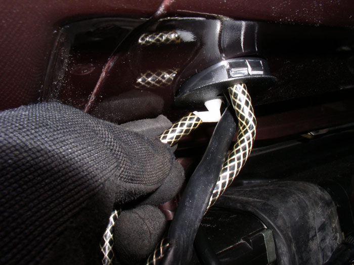
Next comes the windshield washer fluid hose connections. When I removed the hoses, you may remember that I marked (taped) one of the hoses with "external" because one of the hoses was connected external to the hood and the other hose was connected internally. First, connect the internal hose fitting. On mine, it was located up inside the hood. After locating it.....
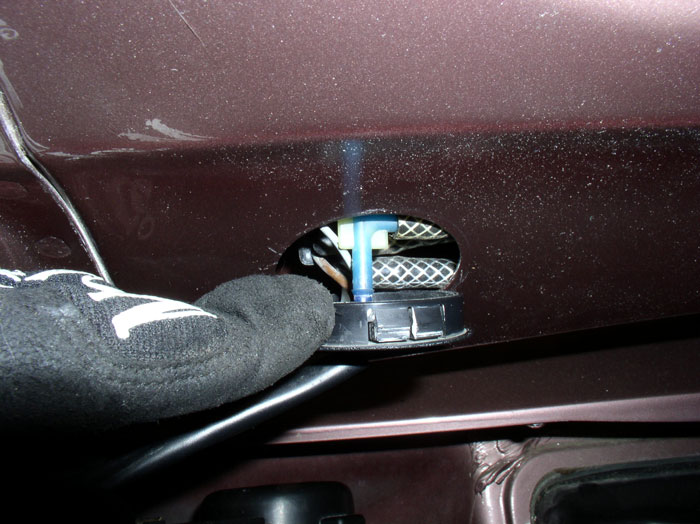
....push it down through the hole in the plastic cover plate and connect the "internal" hose.
Then, connect the "external" hose to the other external fitting.
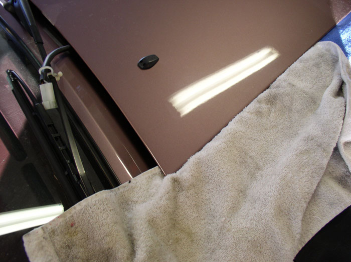
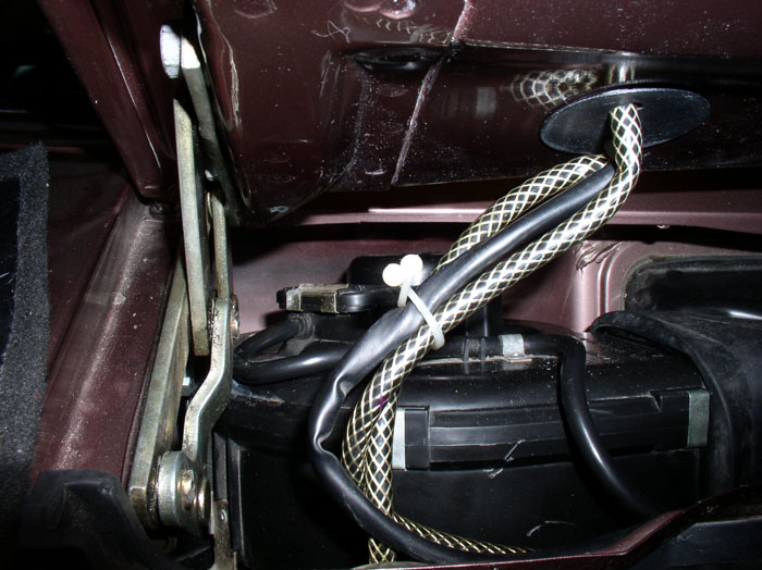
Fit the plastic cover over the hole in the hood and push it in until it snaps into place. Bundle the wire and hoses together with a plastic bungee or zip tie.
continued......
If you're working alone, like me, lay out your bolts and shims and wrenches so they are easily accessable near the hinges. I had two shims for each side.
Place a towel under the hood near the hinge and cowl to protect it from scratches. I also left the service covers on for fender protection. Bring the hood over and gently lay it into position as shown.
Next, lift up one side of the hood at the hinge and insert the shims. Line up the holes for the front bolt and install the 13mm bolt - I used the 13mm socket and 3" extension bar. Do the same for the other side of the hood.
I then lifted the hood with one hand and used the other to start the rear bolt using the extension again. The objective is to simply get the bolt well started in the hole. Do the same for the other side of the hood.
Next, support the hood with a wooden or rubber tipped rod. I used a clothes hangar dowel you find in your closet. Remove the service covers at this time so you can check for proper alignment.
Now you can fine tune the adjustment. First position the hinge so that it is approximately where it was when you removed it. I was carefull not to wash or wax the area at the hinge since the original 'dirt' left a marker where the hinge should go.
When it's lined up as close as you can get it to it original position, snug all four of the bolts down LIGHTLY - just enough to hold them in place as you make final adjustments.
Move to the front of the hood and check the alignment of the hood pin to the receiver latch. It should be perfectly centered in the hole. Mine was very close on first try but I had to fine tune it. Do not try to latch the hood (i.e., press it all the way down into the receiver) unless it looks perfectly centered - otherwise it can get wedged in there and be difficult to "unlatch". If it's not lined up perfectly, raise and support the hood enough to gain access to the bolts at the hinges and loosen enough to adjust the hood slightly. For example, when looking at the hood from the front of the car, my hood pin was a little to the left of the center of the receiver hole. I loosened the passenger side bolts at the hinge and moved the hood forward about 1/16 of an inch then snugged the bolts down again. Then go to the pin and receiver at the front and check alignment again. It took me two adjustments to get it centered. It's trial and error mixed with a little patience and you can get it perfect. When it's aligned in the center of the receiver, close the hood all the way and try opening it from the hood release lever in the car to check for normal operation. I have found this method also ensures the gaps between the hood and fender consistenly come out even as well. The final adjustment check to make is hood height. It should be flush with the fenders. If it's too high or low, you will need to make an adjustment at the hinge again. This time, when you loosen the bolts, simply raise or lower the hood a the hinge to get the right height - trick is to keep the bolts snug enough that you can move the hood at the hinge without allowing it to slip forward or back. After the height adjustment, check for normal operation again.
When the hood operation checks out, torque the 13mm hood bolts to 15 ftlbs.
Next, make the electrical connections. There should be a 2 pin connector and a 3 pin connector to the hood. These are for the heated windshield washer nozzles and hood light. Make both of these connections as shown.
Next comes the windshield washer fluid hose connections. When I removed the hoses, you may remember that I marked (taped) one of the hoses with "external" because one of the hoses was connected external to the hood and the other hose was connected internally. First, connect the internal hose fitting. On mine, it was located up inside the hood. After locating it.....
....push it down through the hole in the plastic cover plate and connect the "internal" hose.
Then, connect the "external" hose to the other external fitting.
Fit the plastic cover over the hole in the hood and push it in until it snaps into place. Bundle the wire and hoses together with a plastic bungee or zip tie.
continued......
Last edited by Dwayne; 02-09-2009 at 12:36 AM.
 02-08-2009, 06:34 PM
#152
Three Wheelin'
Thread Starter
Join Date: Sep 2007
Location: Ridgecrest, California
Posts: 1,363
Likes: 0
Received 146 Likes
on
30 Posts
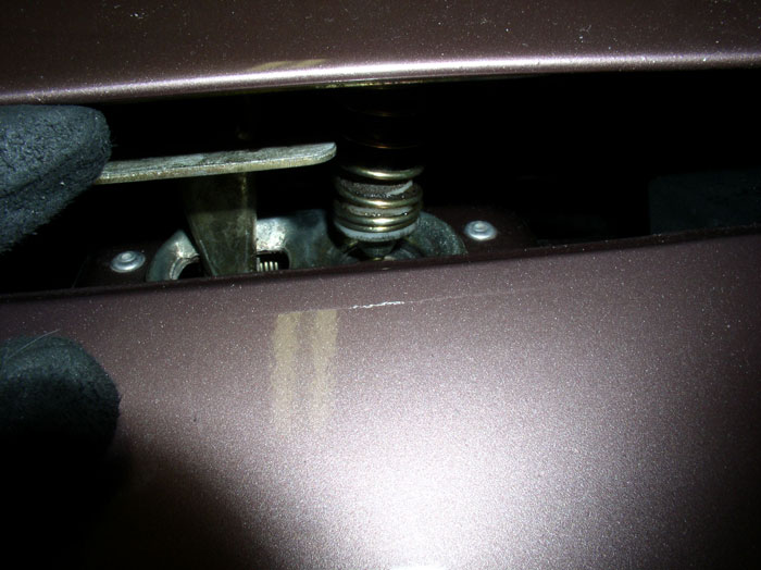
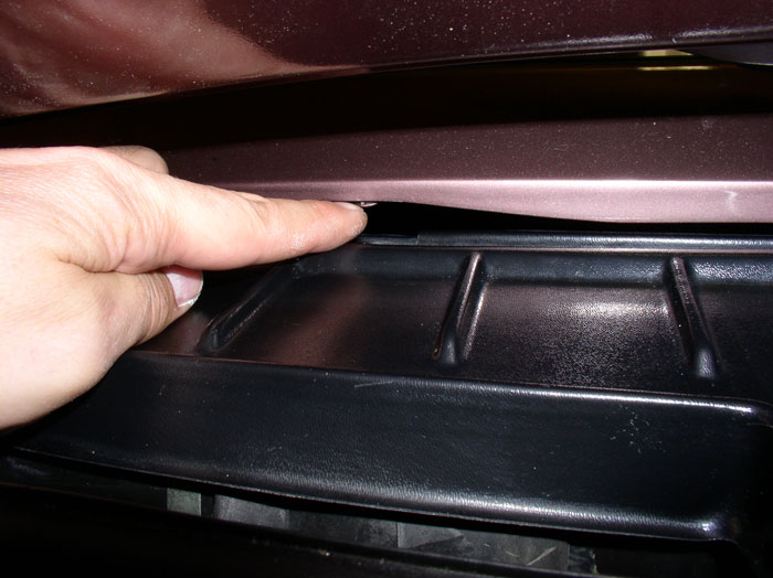
Now you can install the wiper motor and fan blower motor cover. Place the cover into position, guiding the hood wires at each end into their recessed openings.
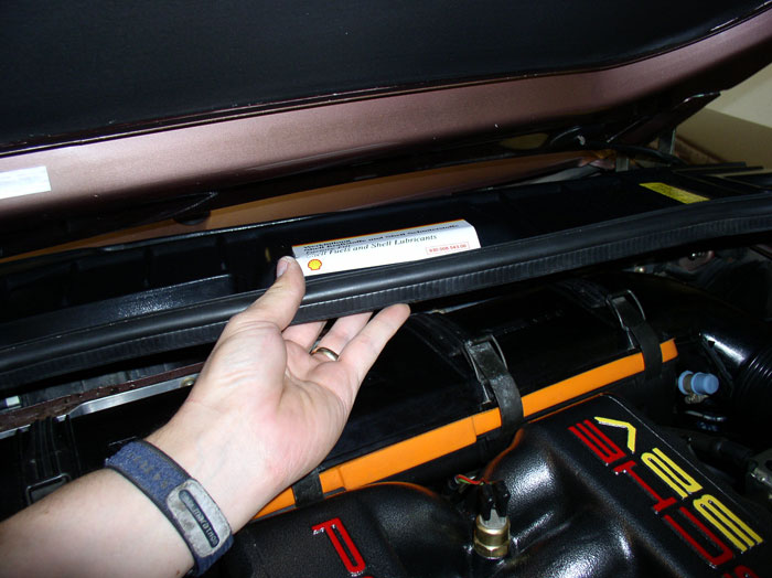
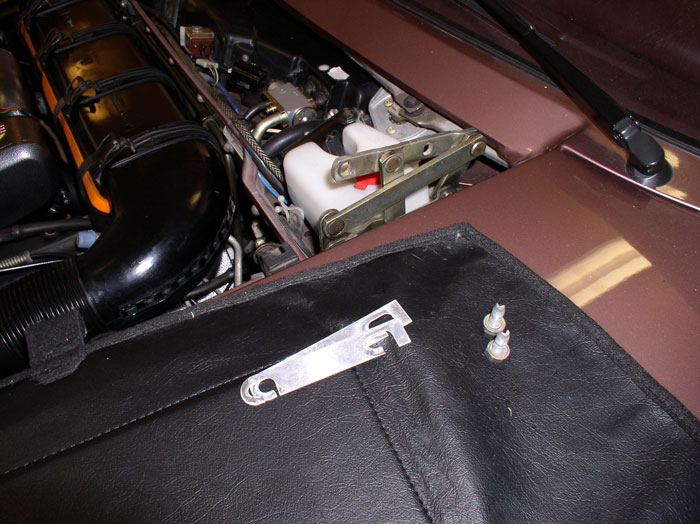
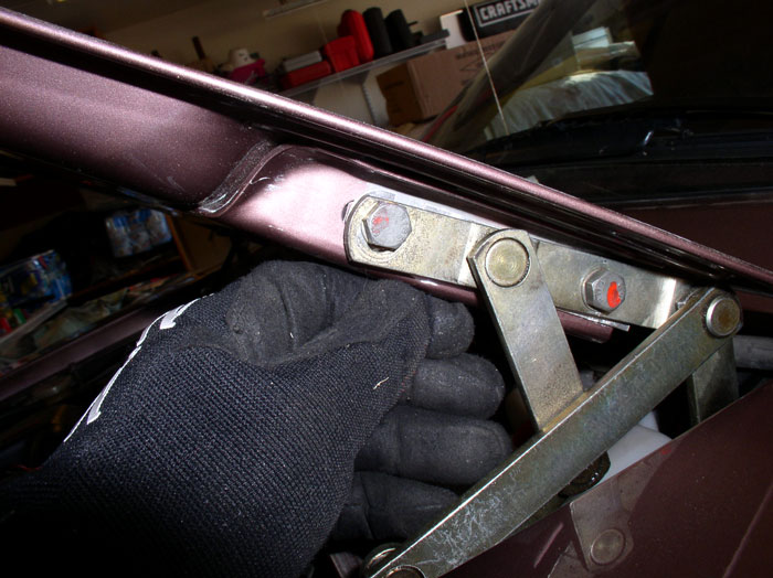
There are two tabs that hold the rear edge of the cover in place. They are located just under the cowl. Ensure the rear edge of the plastic cover fits on top of these tabs and slides under the cowl. See pic below where tab is at the end of my finger. I needed to pry one of my tabs open slightly as it looked like it was too tight to allow the cover to slip in.
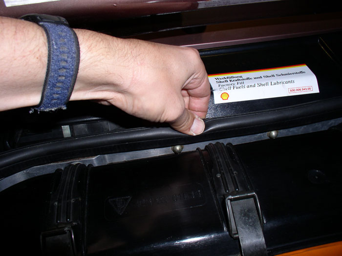
Next, press the front of the cover down over the firewall top edge.
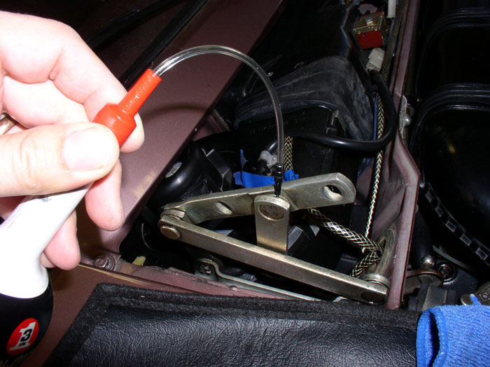
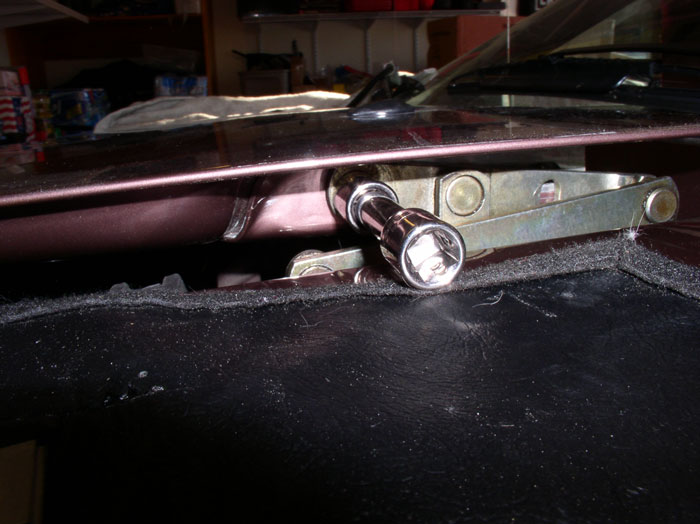
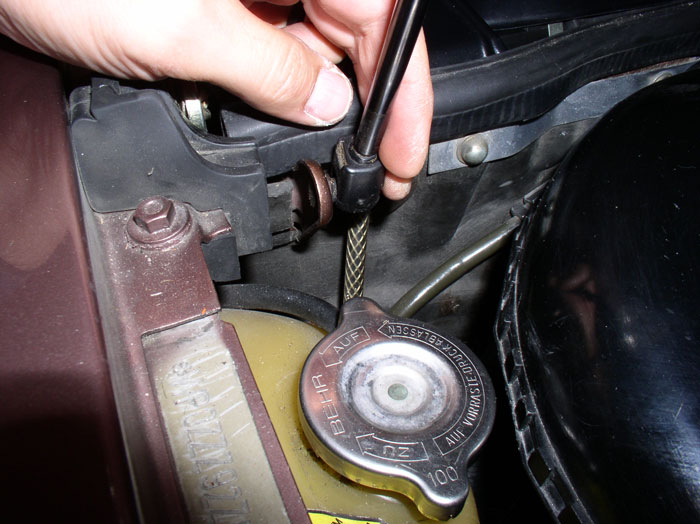
Attach the bottom of the hood shock to the ball connector as shown. These connections simply "snap" on without the use of a tool.
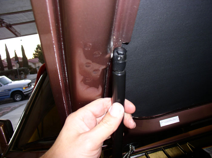
Attach the top of the hood shock to the ball connector on the hood as shown.
And FINALLY, you're DONE! It should look something like this.
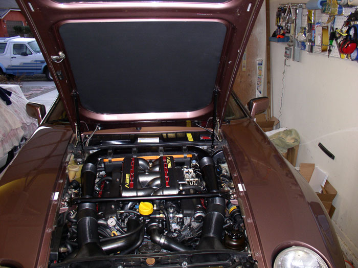
For those of you following along at home, CONGRATULATIONS on your intake removal, repair and installation!
My wife and I are very happy with the end result, it cleaned up the engine and now it runs fantastic. This was also a TREMENDOUS learning experience for me (being my first S4 intake job). Many forum members have offered valuable and insightful advice and tips along this thread and it has been of great help to me and has improved the overall quality of the thread - I would like to say THANK YOU! I also extend the offer to all to continue to provide comments or additional tips that will contribute to the quality of this thread - I'm always looking for better ways of performing this work.
I trust this thread is helpful for other newbie first timers like myself - that was my goal - even it was a few more pictures than I had planned (more than 630 in total).
Next, I'm going through the thread and perform some clean up and try to address all the comments and input. Then, if Randy's offer is still open, I believe it will be copied to the DIY section for 928. THANKS again and ENJOY!
There are two tabs that hold the rear edge of the cover in place. They are located just under the cowl. Ensure the rear edge of the plastic cover fits on top of these tabs and slides under the cowl. See pic below where tab is at the end of my finger. I needed to pry one of my tabs open slightly as it looked like it was too tight to allow the cover to slip in.
Next, press the front of the cover down over the firewall top edge.
Attach the bottom of the hood shock to the ball connector as shown. These connections simply "snap" on without the use of a tool.
Attach the top of the hood shock to the ball connector on the hood as shown.
And FINALLY, you're DONE! It should look something like this.
For those of you following along at home, CONGRATULATIONS on your intake removal, repair and installation!
My wife and I are very happy with the end result, it cleaned up the engine and now it runs fantastic. This was also a TREMENDOUS learning experience for me (being my first S4 intake job). Many forum members have offered valuable and insightful advice and tips along this thread and it has been of great help to me and has improved the overall quality of the thread - I would like to say THANK YOU!
I also extend the offer to all to continue to provide comments or additional tips that will contribute to the quality of this thread - I'm always looking for better ways of performing this work.I trust this thread is helpful for other newbie first timers like myself - that was my goal - even it was a few more pictures than I had planned (more than 630 in total).
Next, I'm going through the thread and perform some clean up and try to address all the comments and input. Then, if Randy's offer is still open, I believe it will be copied to the DIY section for 928. THANKS again and ENJOY!
Last edited by Dwayne; 02-09-2009 at 09:56 PM.
02-09-2009, 08:58 PM
#154
Addict
Rennlist Member
Rennlist Member
Join Date: Apr 2004
Location: Kihei, Hawaii
Posts: 813
Likes: 0
Received 0 Likes
on
0 Posts
Dwayne:
Awesome write-up. This is a project I've dreaded for a long time but hope to get it done soon. I have the intake gaskets, hoses, etc already, plus the front and rear gasoline lines. I hope mine turns out as great as yours. If you want to visit the Commonwealth of Virginia, let me know. I've got plenty of tools and beer.
I was in your neck of the woods about four weeks ago....a ski trip to Mammmoth. I probably flew over Ridgecrest on the way there.
02-09-2009, 09:18 PM
#155
Rennlist Member
Great job on the write-up and photo documentation Dwayne.
Your intake/cam covers look amazing!
Your intake/cam covers look amazing!
02-09-2009, 09:33 PM
#156
Rennlist Member
Been following this thread because it's just cool. Great work Dwayne! 
I'm convinced you have a hand model for the "shoot".
Out of the 630+ pics, I think this is the "money shot"
I'm convinced you have a hand model for the "shoot".
Out of the 630+ pics, I think this is the "money shot"
02-16-2009, 09:14 PM
#157
Basic Sponsor
Rennlist
Site Sponsor
Rennlist
Site Sponsor
Well after a lot of effort from Danny Gates at Home Depot I have managed to secure some of the gauges for the vauum test kit originally developed by Shocki and during this thread by Dwayne.
Kit consists of the 3" to 2" reducer, Gauge, adapter and 2" to 3/4" plug.
Price is $28.40 plus shipping.
Kit consists of the 3" to 2" reducer, Gauge, adapter and 2" to 3/4" plug.
Price is $28.40 plus shipping.
__________________

Does it have the "Do It Yourself" manual transmission, or the superior "Fully Equipped by Porsche" Automatic Transmission? George Layton March 2014
928 Owners are ".....a secret sect of quietly assured Porsche pragmatists who in near anonymity appreciate the prodigious, easy going prowess of the 928."
Does it have the "Do It Yourself" manual transmission, or the superior "Fully Equipped by Porsche" Automatic Transmission?
George Layton March 2014928 Owners are ".....a secret sect of quietly assured Porsche pragmatists who in near anonymity appreciate the prodigious, easy going prowess of the 928."

 03-17-2009, 01:14 AM
#160
Three Wheelin'
Thread Starter
Join Date: Sep 2007
Location: Ridgecrest, California
Posts: 1,363
Likes: 0
Received 146 Likes
on
30 Posts
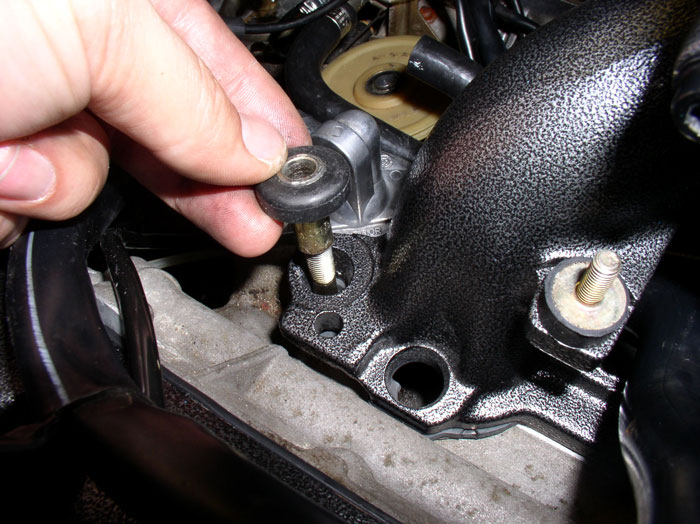
I've received some great comments on this post about the orientation of the intake thrust washer sleeve. You may recall (a few pictures back) that I installed the sleeve with the flange oriented up as seen in the pictures below.
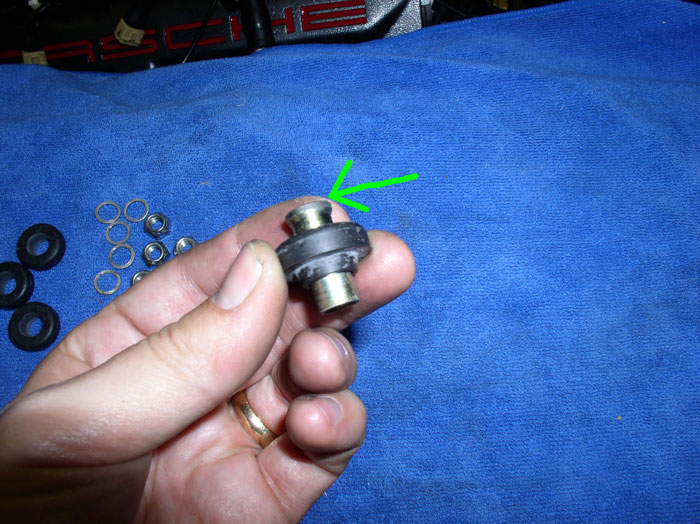
However, when I was removing the old thrust washers from the intake, I noticed they were installed with flange down and the sleeve had to be removed out the bottom of the intake as pictured below. I"m not sure why this orientation is found on the factory intallation. Perhaps this orientation aided installation of the intake at the factory. Or perhaps it aided centering of the intake over the studs.
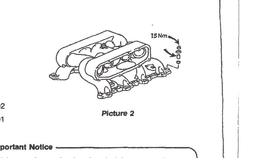
I've been doing some research in order to determine what is the correct orientation of the intake thrust washer sleeve - flange up or flange down. I did not find any reference or help in the WSM. When I found the picture of the parts exploded view of the intake washer assembly (at the time I performed the re-install), it appeared to indicate the flange of the sleeve should be oriented up. The picture below is from the Tech bulletins 1984-1993 bulletin #8701 "Engine Performance Intake Manifold Leaks". It's the same diagram found in the PET as well.
The order seems to be rubber thrust washer on the bottom (first) then the metal sleeve, then the large umbrella washer, then the nut (last). The only way I could find to install in this order is with the flange oriented up. However, based on some of the comments received, some virgin disassemblies of factory installed intakes have the flange oriented down. Unfortunately, I can't explain the difference between what may be the factory installation vs. the apparent recommended installation from the PET and Tech Bulletin. Therefore, I can only offer the following recommendation:
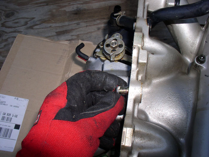
The length of the sleeve is the important factor here. It should function the same whether it is installed with flange down or flange up. If it is installed with flange down, it can be installed on the intake studs first (with flange down) before setting the intake down on the intake studs. Or, it can be installed on the intake from underneath (as shown in the third picture above) and secure the sleeve in place by installing the rubber thrust washer from the top to hold the sleve in place. Then install the intake over the studs and finish by installing the umbrella washer and lock nut.
If it is installed with flange up, as the pictures from the PET and tech bulletin would seem to suggest, the sleeve and thrust washer can be installed from on top as is documented in this thread. I believe this may be more of a matter of personal preference and the end result in performance should be the same.
I have edited the respective part of the post to include some of this discussion. Again, thanks for the great comments and the help in improving the quality of this post and procedure!
However, when I was removing the old thrust washers from the intake, I noticed they were installed with flange down and the sleeve had to be removed out the bottom of the intake as pictured below. I"m not sure why this orientation is found on the factory intallation. Perhaps this orientation aided installation of the intake at the factory. Or perhaps it aided centering of the intake over the studs.
I've been doing some research in order to determine what is the correct orientation of the intake thrust washer sleeve - flange up or flange down. I did not find any reference or help in the WSM. When I found the picture of the parts exploded view of the intake washer assembly (at the time I performed the re-install), it appeared to indicate the flange of the sleeve should be oriented up. The picture below is from the Tech bulletins 1984-1993 bulletin #8701 "Engine Performance Intake Manifold Leaks". It's the same diagram found in the PET as well.
The order seems to be rubber thrust washer on the bottom (first) then the metal sleeve, then the large umbrella washer, then the nut (last). The only way I could find to install in this order is with the flange oriented up. However, based on some of the comments received, some virgin disassemblies of factory installed intakes have the flange oriented down. Unfortunately, I can't explain the difference between what may be the factory installation vs. the apparent recommended installation from the PET and Tech Bulletin. Therefore, I can only offer the following recommendation:
The length of the sleeve is the important factor here. It should function the same whether it is installed with flange down or flange up. If it is installed with flange down, it can be installed on the intake studs first (with flange down) before setting the intake down on the intake studs. Or, it can be installed on the intake from underneath (as shown in the third picture above) and secure the sleeve in place by installing the rubber thrust washer from the top to hold the sleve in place. Then install the intake over the studs and finish by installing the umbrella washer and lock nut.
If it is installed with flange up, as the pictures from the PET and tech bulletin would seem to suggest, the sleeve and thrust washer can be installed from on top as is documented in this thread. I believe this may be more of a matter of personal preference and the end result in performance should be the same.
I have edited the respective part of the post to include some of this discussion. Again, thanks for the great comments and the help in improving the quality of this post and procedure!
03-17-2009, 02:03 AM
#161

These are some great pictures. Love the clean car.
03-17-2009, 10:44 AM
#162
Burning Brakes
Join Date: Jan 2009
Location: Woodbridge, VA.
Posts: 961
Likes: 0
Received 0 Likes
on
0 Posts
Thanks for clearing that up for me Dwayne..3-4 of mine were down when I took it apart and it made sense to me to have them in the upward position so the rounded washer would have a larger surface area to center on and also since they slid in and out of the intake hole anyway, it made no sense for me to try and position them down. Probably just a factory assembly procedure that was not specified one way or another, Thanks for all the GREAT pics and tips! Kevin L. 88 S4 Guards Red AT
03-17-2009, 06:34 PM
#163
Addict
Rennlist Member
Rennlist Member
Join Date: Oct 2003
Location: Gone. On the Open Road
Posts: 16,436
Received 1,607 Likes
on
1,050 Posts
I'll have a loose intake next week and I will ponder this question further.
03-29-2009, 04:31 PM
#165
Drifting