
Screw it: "Sheet Metal" intakes
 08-24-2008, 01:49 AM
#151
Rennlist Member
Thread Starter

Very nice hammer. The issue is that I want to remove alot of the "I have to figure out how to cut aluminum in large quantities and then weld it with high precision"
I just simply don't have the resources, nor the time or experience to get it done as simply as you did. When I was working on my heads, I was using a god damned dremel. And to be able to weld the runner to the proper location on the plate with reference to the head port - who is going to do that for me?
The reason I want it at an angle is so the angle is fixed for a straight ended runner. Then I would put a locating hole in the piece to accept the OD of the runner, and I would do another hole smaller, and I would have to port match that hole like you did.
But your second picture is exactly the shape I have always had in my head, except its flat. Its great. But my question is - what about the divet at the inner side of the port that is scalloped out for the injector stream?
 08-24-2008, 01:09 PM
#152
Nordschleife Master
Brendan,
Take a paper gasket which is port matched to your ported heads, then take that gasket to a waterjet cutting place and they can cut you steel flanges (bolt holes and everthing) for a very reasonable cost. Then you will only have alittle matching to do.
Take a paper gasket which is port matched to your ported heads, then take that gasket to a waterjet cutting place and they can cut you steel flanges (bolt holes and everthing) for a very reasonable cost. Then you will only have alittle matching to do.
08-24-2008, 02:13 PM
#153
Rennlist Member
Very nice hammer. The issue is that I want to remove alot of the "I have to figure out how to cut aluminum in large quantities and then weld it with high precision"
I used a 968 gasket for the templates to cut the holes for the ports. I used a stock 928 intake manifold to locate the bolt holes using a transfer punch. You're very capable of doing that I'm sure.
I just simply don't have the resources, nor the time or experience to get it done as simply as you did. When I was working on my heads, I was using a god damned dremel. And to be able to weld the runner to the proper location on the plate with reference to the head port - who is going to do that for me?
I can't weld aluminum so I took it to a shop & paid to have it welded. You could do the same.
The reason I want it at an angle is so the angle is fixed for a straight ended runner. Then I would put a locating hole in the piece to accept the OD of the runner, and I would do another hole smaller, and I would have to port match that hole like you did.
I found it much easier to have a flat plate & to angle the tubes than angling the plate.
But your second picture is exactly the shape I have always had in my head, except its flat. Its great. But my question is - what about the divet at the inner side of the port that is scalloped out for the injector stream?
Uh oh, half of my response ended up inside the box with your quote,- see what I mean about my computer skills?!
Hammer
08-24-2008, 03:35 PM
#154
Rennlist Member
Thread Starter
Thanks. My ports have not really been enlarged. All I did was smooth the transitions by the bowls and seats.
So with that, If a port match is done to the main shape, there would be a ridge just under the flange.
Is this a bad thing?
So with that, If a port match is done to the main shape, there would be a ridge just under the flange.
Is this a bad thing?
08-24-2008, 06:08 PM
#155
Three Wheelin'
It's probably a good thing for a street engine. The void under the flange will create turbulence in that area and help re-introduce fuel on the wall back into the air stream. You can always use a die grinder to reduce the overhang too.
08-24-2008, 06:22 PM
#156
Rennlist Member
Thread Starter
My quandry is that the heads have been rebuilt (again), cleaned, assembled, and already torqued down (first 90 degrees was last night, today will be the second 90 degrees, and monday the last)
So any grinding to match stuff will need to be in a separate part of the garage away from the clean assembled engine.
But I like the turbulence idea.
So any grinding to match stuff will need to be in a separate part of the garage away from the clean assembled engine.
But I like the turbulence idea.
08-24-2008, 08:55 PM
#157
Three Wheelin'
My quandry is that the heads have been rebuilt (again), cleaned, assembled, and already torqued down (first 90 degrees was last night, today will be the second 90 degrees, and monday the last)
So any grinding to match stuff will need to be in a separate part of the garage away from the clean assembled engine.
But I like the turbulence idea.
So any grinding to match stuff will need to be in a separate part of the garage away from the clean assembled engine.
But I like the turbulence idea.
 08-24-2008, 10:37 PM
#158
Rennlist Member
Thread Starter
Always my friend, always.
08-28-2008, 12:09 PM
#159
Burning Brakes
Brendan, like this? Base is drawn 3/4" stock. 2 setups on a mill to achieve this. One tool.
Tube at 15 degree angle, drawn 2" OD at random because I don't know what actual specs are. Just for demonstration.
Tube at 15 degree angle, drawn 2" OD at random because I don't know what actual specs are. Just for demonstration.
08-28-2008, 12:56 PM
#160
Rennlist Member
Thread Starter
That is very nearly what I was talking about. I can see that you know how to make the hole a variable shape. That was something I did not learn yet. Beautiful.
Interesting point: The "front" of the port - the side opposite of the injector area - is at about a 20 degree entry angle. But the "back" of the port - the injector side, is nearly straight down. Everyone has suggested a smaller hole than required for the port side of the flange, and the hand porting.
I received your email. I am responding now. Thanks!
09-04-2008, 01:07 PM
#161
Rennlist Member
Thread Starter
It looks like my ideas are comming much closer to fruition. Add some more time, some more measurements, and some help from a fellow rennlister, I think I may have an intake flange soon, which to me is the most important part of the intake.
This is an innitial version of what I have been envisioning since the beginning:
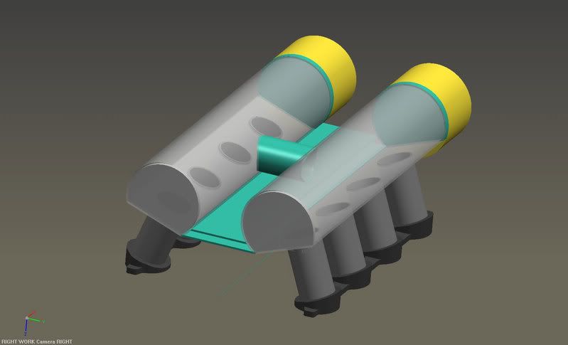
The balance tube could be made larger, or use three of them, or the green plate would be made to box off the middle section of the "D-shaped plenum" from Ross Machine Racing. A plate on top, the botton, and the front and back.
THREE balance tubes, maybe 3" in diameter, may be an easier plan however.
Two Ford Mustange 75mm throttle bodies at the front (signified by the yellow), and boom - a nice intake manifold.
The 4" runners could be a bit shorter, but it seemed a good compromise.
Currently, with the measurements, it looks like I will need a small hood bulge. But thats such a small price to pay for a cool intake.
This is an innitial version of what I have been envisioning since the beginning:
The balance tube could be made larger, or use three of them, or the green plate would be made to box off the middle section of the "D-shaped plenum" from Ross Machine Racing. A plate on top, the botton, and the front and back.
THREE balance tubes, maybe 3" in diameter, may be an easier plan however.
Two Ford Mustange 75mm throttle bodies at the front (signified by the yellow), and boom - a nice intake manifold.
The 4" runners could be a bit shorter, but it seemed a good compromise.
Currently, with the measurements, it looks like I will need a small hood bulge. But thats such a small price to pay for a cool intake.
09-04-2008, 03:12 PM
#162
Rennlist Member
Brendan,
Why dont you try a model with curved runners that feed the opostite plenum? that way you get an even longer runner, and you can reduce the overall height to fit under the stock hood. You should at least model it so you can see what it looks like.
Hans
Why dont you try a model with curved runners that feed the opostite plenum? that way you get an even longer runner, and you can reduce the overall height to fit under the stock hood. You should at least model it so you can see what it looks like.
Hans
09-04-2008, 03:46 PM
#163
Rennlist Member
Thread Starter
This is all a compromise. I hope I am on the right track, but I have to make decisions along the way that make sense for the end product. It will cost me thousands and thousands of dollars, really, to make a curved runner intake. If I keep it straight, its only many 100s. for the work, machining, and pieces.
09-04-2008, 03:49 PM
#164
Rennlist Member
Thread Starter
Hans -
This is why I am not worrying about longer runners: 27psi (at redline) 5.0L 32V engine analyzed with 4" and 8" runners. 4" is the higher one.
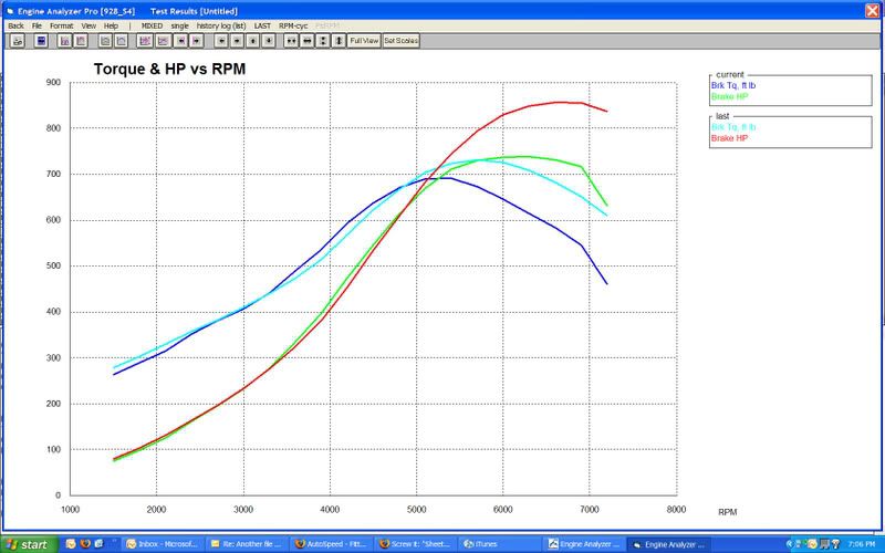
This is why I am not worrying about longer runners: 27psi (at redline) 5.0L 32V engine analyzed with 4" and 8" runners. 4" is the higher one.
09-04-2008, 04:50 PM
#165
Rennlist Member
Go with what your software tell you. But the curved runners will cost the same, or possibly a negligible amount more for the few extra inches of material. Bending aluminum tube is very easy, and if you make the curve in your software package, and then export it as 100% scale 2D image, it is a perfect template for bending. Take it to an exhaust shop with a mandrel bender, and they should be able to do all the tubes in a few minutes, or get a cheap bender and do it yourself. Cant really mess-up if you have that 2D template, and take your time.
Again, go with what your software tells you, but reducing the height of the intake, and spending the extra couple bucks for longer runners and bending at your local shop will be a lot less then the custom bodywork on the hood to clear a "high-rise" manifold.
Either way, i am excited to see your results, and each draft is really showing improvement.
Hans