

Screw it: "Sheet Metal" intakes
 08-19-2008 | 12:17 AM
#136

Thread Starter
Rennlist Member
Joined: Dec 2001
Posts: 25,152
Likes: 87
I think the word I was missing was "flange"... but even with babelfish I have no clue what that means.
Do I understand that stock 928 doesn't really have a flange? Or are the spider's legs flanges? My only point of comparaison is my engine block.
I'm asking because I think I would like to try the exercise myself... Even if it will probably give no result at all.
Anywhere I could find size blueprint of the top of the cams?
08-19-2008 | 12:19 AM
#137
Thread Starter
Rennlist Member
Joined: Dec 2001
Posts: 25,152
Likes: 87
Mmmhhmm. I think I just look hard at the details to make more eloquent solutions. You should see my prose. I always got published, but I was always asked by the editor to "Cut some fat"
 08-19-2008 | 11:16 AM
#141
Rennlist Member
Joined: Aug 2003
Posts: 2,623
Likes: 294
From: Indianapolis
The flange should be relatively inexpensive if you keep the design simple. Use the drawing you posted several pages back. "Extrude" the part so it is slightly thicker, enough room to allow translation of the non-standard porsche port to say the oval tubing sold by RMR. Then create two separate drawings from here. In one drawing place the intake bolt holes and the smaller of the two port shapes centered on the flange. You can then flatten this drawing to 2D if you prefer, as this will go to the waterjet cutter.
On your second drawing, you start with the basics of the first. So you have a thick flange with some holes cut strati through it. From here you add the second, larger port size (either on the top or bottom of the flange, depending if the runner is larger than the port. Then sculpt the transition of the port size to the runner size. On the opposite side of the flange, design your recess for the runner, as you show in previous drawings.
Using this 2-stage process, you have most of the heavy cutting done on the waterjet, which is much less expensive. Then your multi-axis matching is only to create the port match and runner relief. Last set of flanges i had cut were for a turbo manifold in 321SS, and the material and labor was around $300 for the exhaust, wastegate, turbo and downpipe flanges. I would imagine your cost would be similar for two intake flanges. The multi-axis machining would be pretty quick. I dont see getting that bill too high either. My assumption is that you could probably get both flanges done material included for around $500.
Hans
08-19-2008 | 11:56 AM
#142
Pro
Joined: Jun 2008
Posts: 695
Likes: 2
From: Qu�bec, Qu�bec, Canada
 08-19-2008 | 12:10 PM
#143
Thread Starter
Rennlist Member
Joined: Dec 2001
Posts: 25,152
Likes: 87
08-19-2008 | 12:25 PM
#144
Thread Starter
Rennlist Member
Joined: Dec 2001
Posts: 25,152
Likes: 87
The flange should be relatively inexpensive if you keep the design simple. Use the drawing you posted several pages back. "Extrude" the part so it is slightly thicker, enough room to allow translation of the non-standard porsche port to say the oval tubing sold by RMR. Then create two separate drawings from here. In one drawing place the intake bolt holes and the smaller of the two port shapes centered on the flange. You can then flatten this drawing to 2D if you prefer, as this will go to the waterjet cutter.
On your second drawing, you start with the basics of the first. So you have a thick flange with some holes cut strati through it. From here you add the second, larger port size (either on the top or bottom of the flange, depending if the runner is larger than the port. Then sculpt the transition of the port size to the runner size. On the opposite side of the flange, design your recess for the runner, as you show in previous drawings.
Hans
08-19-2008 | 01:47 PM
#145
Rennlist Member
Joined: Aug 2003
Posts: 2,623
Likes: 294
From: Indianapolis
If you want the angle to be in the flange and not on the runners, then yes, the above would not apply. How many degrees of angle are you looking for. Waterjet loose their tolerance on thick cuts. I have heard that it is possible to cut aluminum 2" or thicker with average commercial waterjets, but not sure i would expect tolerances at that point. I think perhaps you have engineered yourself in a corner.
What exactly is the reason you dont want to cut the runners at an angle?
What exactly is the reason you dont want to cut the runners at an angle?
08-19-2008 | 03:48 PM
#146
Thread Starter
Rennlist Member
Joined: Dec 2001
Posts: 25,152
Likes: 87
If you want the angle to be in the flange and not on the runners, then yes, the above would not apply. How many degrees of angle are you looking for. Waterjet loose their tolerance on thick cuts. I have heard that it is possible to cut aluminum 2" or thicker with average commercial waterjets, but not sure i would expect tolerances at that point. I think perhaps you have engineered yourself in a corner.
What exactly is the reason you dont want to cut the runners at an angle?
What exactly is the reason you dont want to cut the runners at an angle?
BUt your idea and the idea of some personal communications make perfect sense. Keep it simple stupid (to me). This way I can deal with the issues of atomization better with those injector bungs higher up the runner - as I have read that the larger the injector, the more time it needs to properly atomize - people say I can't just shove a 160lb injector right near the valve backside where a 19lb one was there before and expect it to run smoothly.
Location of the injector is not critically important, it just seems to make difference when they get big:

Caption on this pic reads:
Two Duttweiler sheetmetal intakes: A 1,600hp Buick V-6 high-rpm drag-race motor responded well to a high injector location (left). Compared with the manifold in the big photo at right, Duttweiler 's previous-generation Chevy V-8 intake (above right) had 1/4-inch longer runners and lower-mounted injectors. The reason for the change was improved fuel atomization at 10,000 rpm.

Caption reads:
Duttweiler's 294ci twin-turbo small-block Chevy makes 2,000 hp on 38 psi of boost using 165 lb/hr injectors. The biggest available, they can support roughly 300 hp each. The new intake shown here locates the injectors slightly more than halfway toward the plenum. Compared with the old intake with lower injectors, the new location plus shorter runners gained 50 hp.
08-23-2008 | 10:12 PM
#147
Thread Starter
Rennlist Member
Joined: Dec 2001
Posts: 25,152
Likes: 87
I have redesigned the original piece to reflect the advice given here and in PMs. Thanks to all who suggested things - I appreciate the input as I am very willing to learn, and grow.
How about this?
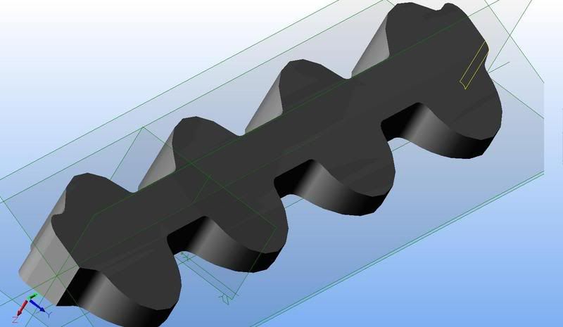
How about this?

