
Screw it: "Sheet Metal" intakes
 08-01-2008, 10:37 PM
#1
Rennlist Member
Thread Starter

Which really means aluminum intakes welded together.
The current S4 intake is working. Thats fine. But I think its a very large restriction, as well as causing massive differences in actual air mass, even with boost. That last part is proven.
I could have two plenums welded together and connected with one butterfly valve, just like the OEM one, but without the convoluted was it gets the air to the valves.
Comments?
EDIT (11/07/08)
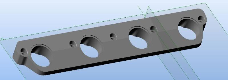
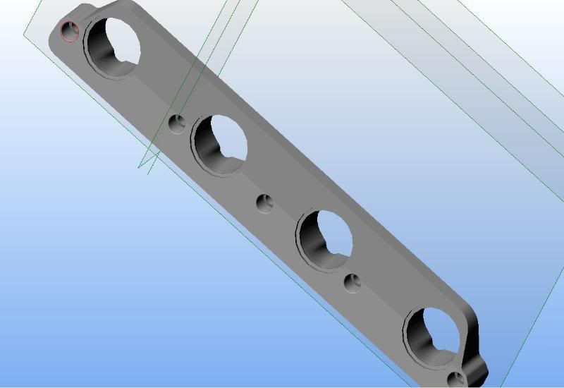
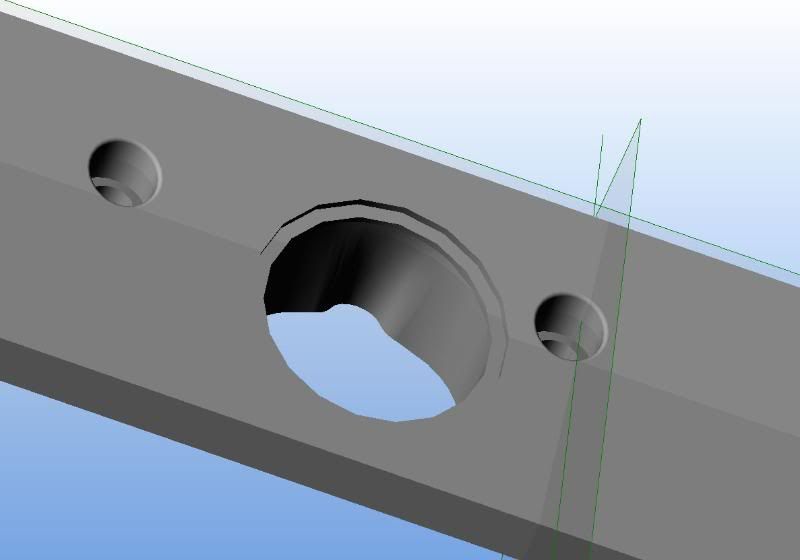
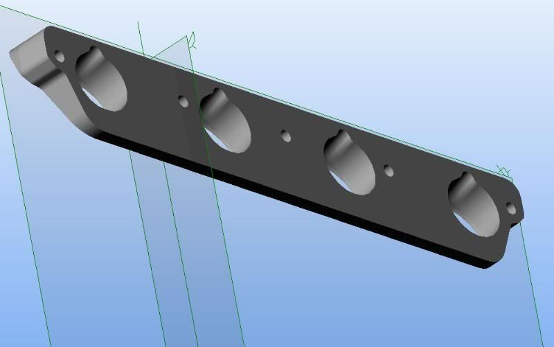
With the help of Porken, Joe (90S4), Todd in Green Bay, and most importantly, a currently un-named "sponsor" who has done extensive drawing and shaping work with CAD 3D tools, I now have what I imagined a few months ago: A nearly ready to machine "intake flange" that is the basis of my custom intake manifold, and could be the modular basis for other as well:
And a picture from the foam core 2D mock-up:
The current S4 intake is working. Thats fine. But I think its a very large restriction, as well as causing massive differences in actual air mass, even with boost. That last part is proven.
I could have two plenums welded together and connected with one butterfly valve, just like the OEM one, but without the convoluted was it gets the air to the valves.
Comments?
EDIT (11/07/08)
With the help of Porken, Joe (90S4), Todd in Green Bay, and most importantly, a currently un-named "sponsor" who has done extensive drawing and shaping work with CAD 3D tools, I now have what I imagined a few months ago: A nearly ready to machine "intake flange" that is the basis of my custom intake manifold, and could be the modular basis for other as well:
And a picture from the foam core 2D mock-up:
Last edited by BC; 11-06-2008 at 07:39 PM.
 08-01-2008, 10:56 PM
#3
Rennlist Member
Thread Starter
08-01-2008, 11:04 PM
#5
Rennlist Member
Thread Starter
Ah. I am just concerned over how much the flappy helps the lower range tq on the normal motor. The big SC will not help much below 3000rpm, so I can't go all hog wild on the intake volume and runner volume/length either.
08-01-2008, 11:11 PM
#6
Nordschleife Master
That isnt the only reason you cant.
Space is pretty limited between the hood and engine. ESP if you want to keep the throttle body going into the V with the MAF in its normal spot.
Space is pretty limited between the hood and engine. ESP if you want to keep the throttle body going into the V with the MAF in its normal spot.
08-02-2008, 10:10 PM
#7
Rennlist Member
Thread Starter

Trending Topics
08-02-2008, 10:43 PM
#8
Chronic Tool Dropper
Lifetime Rennlist
Member
Lifetime Rennlist
Member

Wanna see how much the flappy inproves low-end torque? Bypass the solenoid.
08-02-2008, 11:21 PM
#9
Rennlist Member
Thread Starter
On THESE S4 intakes, I think its about 35flt pounds either way (open or closed at the wrong time)
Its now proven, across the board, by two or three separate people, that the S4 intake, as it stands:
1) Flows about 75-100cfm less than a good set of heads, even with a spacer. (Jim Morton)
2) The flow between runners is up to 25% different, thereby creating LARGE differences in fuel requirements BETWEEN cylinders (Todd)
3) With a HUGE plenum and runner manifold, Mark Anderson was able to to gain 50hp, but because of the size, his NA motor lost big time under a certain RPM (was it 3500rpm)?
08-02-2008, 11:49 PM
#10
Nordschleife Master
Brendan, I had thought about doing a central manifold like that, but the inlet there would be right in the way of where my altenator is. So I will split them up, but I am still needing to do more research to make sure that I am not going to starve the rearward cylinders.
08-03-2008, 02:27 AM
#11
Three Wheelin'
Brendan,
A couple of things to consider....
1. The engine bay cross brace gets in the way so figure on a new one of different design.
2. At the front (#1 cyl) there is 7" of vertical distance from the cyl head/intake mating surface to the underside of the hood. That's with collapsed, or solid motor mounts.
3. The coolant crossover is in the way and some surgery on that will be required for sure by #1 cyl.
4. You can use a single plenum to feed all 8 cyl and it may work, but the short runners will limit low end torque. Bigger plenum is better.
5. If you use two plenums with one feeding one side, and the other feeding the other side, you'll get odd harmonics with very likely torque hole somewhere. That's because of the 90 deg crank uneven firing order on each side. That's not a good route to go. If you have to go that way it's probably better if you have a very small plenum on each side. Similar to the long runner cross ram intake on Dodges back in the day. Either small side plenum and long runners or larger side plenum and very short runners. On both S3 and S4 each side plenum feeds two cyl on one side and two cyl on the other side to utilize the plenum resonance properties. That causes unequal runner lengths and flow, but better than feeding 4 cyl on a side from one side plenum.
08-03-2008, 11:46 AM
#13
Rennlist Member
Thread Starter
Brendan,
A couple of things to consider....
1. The engine bay cross brace gets in the way so figure on a new one of different design.
2. At the front (#1 cyl) there is 7" of vertical distance from the cyl head/intake mating surface to the underside of the hood. That's with collapsed, or solid motor mounts.
3. The coolant crossover is in the way and some surgery on that will be required for sure by #1 cyl.
4. You can use a single plenum to feed all 8 cyl and it may work, but the short runners will limit low end torque. Bigger plenum is better.
5. If you use two plenums with one feeding one side, and the other feeding the other side, you'll get odd harmonics with very likely torque hole somewhere. That's because of the 90 deg crank uneven firing order on each side. That's not a good route to go. If you have to go that way it's probably better if you have a very small plenum on each side. Similar to the long runner cross ram intake on Dodges back in the day. Either small side plenum and long runners or larger side plenum and very short runners. On both S3 and S4 each side plenum feeds two cyl on one side and two cyl on the other side to utilize the plenum resonance properties. That causes unequal runner lengths and flow, but better than feeding 4 cyl on a side from one side plenum.
A couple of things to consider....
1. The engine bay cross brace gets in the way so figure on a new one of different design.
2. At the front (#1 cyl) there is 7" of vertical distance from the cyl head/intake mating surface to the underside of the hood. That's with collapsed, or solid motor mounts.
3. The coolant crossover is in the way and some surgery on that will be required for sure by #1 cyl.
4. You can use a single plenum to feed all 8 cyl and it may work, but the short runners will limit low end torque. Bigger plenum is better.
5. If you use two plenums with one feeding one side, and the other feeding the other side, you'll get odd harmonics with very likely torque hole somewhere. That's because of the 90 deg crank uneven firing order on each side. That's not a good route to go. If you have to go that way it's probably better if you have a very small plenum on each side. Similar to the long runner cross ram intake on Dodges back in the day. Either small side plenum and long runners or larger side plenum and very short runners. On both S3 and S4 each side plenum feeds two cyl on one side and two cyl on the other side to utilize the plenum resonance properties. That causes unequal runner lengths and flow, but better than feeding 4 cyl on a side from one side plenum.
Thanks Louie. I had forgotten about the harmonics on the 4-on-one-side, so that cuts my "two loafs of bread" idea.
The measuring issue was one I was working on. The 7" on Cylinder one is not alot is it.
A. Graham Bell suggests 300-330mm long runners for a street/track car with a centrifugal. That is from valve seat to bell mouth.
I like this one, but it looks very very tall:

And the runners look very short.
08-03-2008, 11:51 AM
#14
Rennlist Member
Thread Starter