
Some pics of installation of S3-based cam in an S4 head
 04-14-2008, 12:56 PM
#1
Addict
Rennlist Member
Rennlist Member
Thread Starter
When we first started, the idea behind my engine rebuild was for it to remain a completely stock S4 aside from reliability/oiling mods. Since then there's been a little mission creep. Once the engine was completely disassembled, it seemed a shame to do all that work & not to at least try and increase performance a little. The cams were the most obvious path to do so as the S4 cams seemed so wimpy. I wanted to run S3 cams which had essentially the same profile as GT cams but without the GT cam price. Then it became only logical that since the S3 cams had to be modified by Elgin Cams to fit an S4 head, we could have them reground at the same time for a little more lift & duration. So after getting my cams back from nitriding & parkerizing, we spent Saturday installing them.
Here is the intake lobe which has been ground to Elgin's 65-6 profile:

Checking for straightness:

To fit the S3 cam to the S4 head, the journal on the driver's side exhaust cam had to be extended (hidden under the cap) and a collar added to re-create the thrust surface (you can see the welds):

Beauty shot of the engine. Thanks to Andre Hedrick for his donation of a factory 928 engine stand mount to the NorCal 928 group.

Another shot of S3 cam in an S4 head. S4 and GT cams are cut off after the rear-most lobe (left-most lobe in this pic). We decided not to cut off the ends of the S3 cams and let them use the bearing surface that still exists in S4 heads.

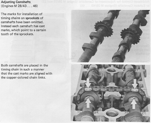
One big oddity of these cams was there were no timing marks on the chain gear. There was also no boss on the passenger intake cam (note that exhaust cam has a boss just left of the chain and the intake is smooth). This made it difficult to determine if we had a correct installation.

We knew that there should be a 114� lobe separation between intake & exhaust cams so we tried eyeballing it at first, but that was impossible. Then we installed a cam wheel and tried to eyeball max lift, but determining if a cam lobe was exactly centered on a lifter was difficult at best. We were getting measurement errors which were not confidence-inspiring.

So in the end, we set up dial indicators. This involved custom machining stainless steel dial indicator extensions thin enough to snake past the U-shaped gap between cam journal & lobe to reach the lifters & custom steel plates for the mounts. This is what the setup looked like:


After figuring out that timing wheel had been moving & causing measurement errors (DOH!), this final setup worked beautifully and we were able to get repeatable numbers that confirmed the installation was good. Big thanks to Jim Morton & Bill Ball for their time, skill & patience, all necessary to make sure that this was done correctly.
Here is the intake lobe which has been ground to Elgin's 65-6 profile:
Checking for straightness:
To fit the S3 cam to the S4 head, the journal on the driver's side exhaust cam had to be extended (hidden under the cap) and a collar added to re-create the thrust surface (you can see the welds):
Beauty shot of the engine. Thanks to Andre Hedrick for his donation of a factory 928 engine stand mount to the NorCal 928 group.
Another shot of S3 cam in an S4 head. S4 and GT cams are cut off after the rear-most lobe (left-most lobe in this pic). We decided not to cut off the ends of the S3 cams and let them use the bearing surface that still exists in S4 heads.
One big oddity of these cams was there were no timing marks on the chain gear. There was also no boss on the passenger intake cam (note that exhaust cam has a boss just left of the chain and the intake is smooth). This made it difficult to determine if we had a correct installation.
We knew that there should be a 114� lobe separation between intake & exhaust cams so we tried eyeballing it at first, but that was impossible. Then we installed a cam wheel and tried to eyeball max lift, but determining if a cam lobe was exactly centered on a lifter was difficult at best. We were getting measurement errors which were not confidence-inspiring.
So in the end, we set up dial indicators. This involved custom machining stainless steel dial indicator extensions thin enough to snake past the U-shaped gap between cam journal & lobe to reach the lifters & custom steel plates for the mounts. This is what the setup looked like:
After figuring out that timing wheel had been moving & causing measurement errors (DOH!), this final setup worked beautifully and we were able to get repeatable numbers that confirmed the installation was good. Big thanks to Jim Morton & Bill Ball for their time, skill & patience, all necessary to make sure that this was done correctly.
 04-14-2008, 01:26 PM
#2

So with a degree wheel that doesn't move, would we still need to make the special brackets?
04-14-2008, 02:03 PM
#3
Three Wheelin'

Join Date: Feb 2002
Posts: 1,663
Likes: 0
Received 0 Likes
on
0 Posts
Yes, you still need a way to hold the dial indicators as well as a way to "sneak" the indicator rod down to the lifter face.
This week, I am working on revision "2" of the degree wheel / indicator setup. Once done, I am sure Dennis will post pics of it for those interested.
This round we simply wanted to confirm the lobe seperation angle between the cams so that we would not have to tear down any of the end seal caps / timing belt setup simply to move the intake cam one tooth if we could get get the the timing to the crank where we want it.
$0.02
04-14-2008, 02:21 PM
#4
Yes, you still need a way to hold the dial indicators as well as a way to "sneak" the indicator rod down to the lifter face.
This week, I am working on revision "2" of the degree wheel / indicator setup. Once done, I am sure Dennis will post pics of it for those interested.
This round we simply wanted to confirm the lobe seperation angle between the cams so that we would not have to tear down any of the end seal caps / timing belt setup simply to move the intake cam one tooth if we could get get the the timing to the crank where we want it.
$0.02
This week, I am working on revision "2" of the degree wheel / indicator setup. Once done, I am sure Dennis will post pics of it for those interested.
This round we simply wanted to confirm the lobe seperation angle between the cams so that we would not have to tear down any of the end seal caps / timing belt setup simply to move the intake cam one tooth if we could get get the the timing to the crank where we want it.
$0.02

I would love to see pictures of the apparatus for the cam timing when its in its final design.
Dema suggested I ask you what size lash caps would be needed with this cam grind on S4 length valves? 1MM or more? Some different size? Thanks.
04-14-2008, 02:33 PM
#5
Rennlist Member
why did the driver intake cam, not have the timing mark on it?
why did elgin weld the cam with the coller? he told me that was not a good idea to weld the cam, or more specifically, you couldnt (or shouldnt) weld the cam. so, thats why he (sparked by Todd's advice)
made a coller that welded to itself, and not the cam.
couldnt you just find a driver side cam, like you previous S4 cams and make a timing mark (raised boss) that coorelated with the proper tooth on the cam sprocket. I mean, you could eye ball that and be realtively sure you were in good shape relative to the exhuaust cam.
I dont think this takes 200 hours to do.
Also, when in doubt, just use the cam setting tool cut out! say you guessed on the 113mm spaced raised boss's, you could then just use the cam lobe tool to verify that the cams are set up correctly. that cant fit in that jig, unless they are timed correctly. one tooth off is very obvious. ball parking with the same boss area of the S4 cam relative to the S3 cams would be a pretty easy way to put the cams in and then verify with the jig tool. By marking the cams where that raised boss would be, you only need to be +/- 20 degrees. very obvious, especially if you have the jig tool. which i have the cut outs for to be made in wood, cardboard or if you wanted to get fancy, aluminum, heck, even sheet aluminum cut out with a sissors However, just making the mark based on the S4 sprocket vs raised boss would save a bunch of this real neat, but time consuming process.
Mk
Do you have any pics of the cam without the bearing over the surface that was modified?
on the cam profile mod, they did more than just base circle cut , right?
did you have to add lash caps, or are you counting on the lifter being able to handle the additional .5mm lift?
why did elgin weld the cam with the coller? he told me that was not a good idea to weld the cam, or more specifically, you couldnt (or shouldnt) weld the cam. so, thats why he (sparked by Todd's advice)
made a coller that welded to itself, and not the cam.
couldnt you just find a driver side cam, like you previous S4 cams and make a timing mark (raised boss) that coorelated with the proper tooth on the cam sprocket. I mean, you could eye ball that and be realtively sure you were in good shape relative to the exhuaust cam.
I dont think this takes 200 hours to do.
Also, when in doubt, just use the cam setting tool cut out! say you guessed on the 113mm spaced raised boss's, you could then just use the cam lobe tool to verify that the cams are set up correctly. that cant fit in that jig, unless they are timed correctly. one tooth off is very obvious. ball parking with the same boss area of the S4 cam relative to the S3 cams would be a pretty easy way to put the cams in and then verify with the jig tool. By marking the cams where that raised boss would be, you only need to be +/- 20 degrees. very obvious, especially if you have the jig tool. which i have the cut outs for to be made in wood, cardboard or if you wanted to get fancy, aluminum, heck, even sheet aluminum cut out with a sissors
However, just making the mark based on the S4 sprocket vs raised boss would save a bunch of this real neat, but time consuming process.Mk
Do you have any pics of the cam without the bearing over the surface that was modified?
on the cam profile mod, they did more than just base circle cut , right?
did you have to add lash caps, or are you counting on the lifter being able to handle the additional .5mm lift?
04-14-2008, 03:02 PM
#6
Inventor
Rennlist Member
Rennlist Member
Originally Posted by Dennis K
Another shot of S3 cam in an S4 head. S4 and GT cams are cut off after the rear-most lobe (left-most lobe in this pic). We decided not to cut off the ends of the S3 cams and let them use the bearing surface that still exists in S4 heads.
Originally Posted by Dennis K
One big oddity of these cams was there were no timing marks on the chain gear. There was also no boss on the passenger intake cam (note that exhaust cam has a boss just left of the chain and the intake is smooth).
Are those insulating intake spacers?
What's with the old school crank idlers?
 04-14-2008, 03:03 PM
#7
Three Wheelin'
Join Date: Feb 2002
Posts: 1,663
Likes: 0
Received 0 Likes
on
0 Posts
Hmmm... Discussing cams here is like discussing NASCAR, best dog breeds or what beer to order at a bar. Regardless of almost anything discussed, it is really, "To each his own..."
IMHO, when you ever you have a re-ground cam, you should not rely on ANY factory markings as there is no basis for its continued use unless discussed well ahead of time with the cam re-grinder and confirmed at time of QA/QC.
Using indicators and degree wheels is the best way to QA / verify the cams for not only being install correctly, but also being the correct grind, as ordered from the re-grinder. FWIW, I have been assembling my engines using the practice as a standard for over 20 years. Folowing this procedure, I have not had to re-time an engine "after the fact", but only for gains relaized during specific dyno tuning moving the timing off the initial setting as the "centered" base line.
With regards to the "welding" question(s)... This "weld" shown here is a silicon-bronze tack-fillet joint, holding the thrust collar only. This is not the same as "welding" a cam or welding on the lobes. IMO, these are very different concerns.
$0.02
Trending Topics
04-14-2008, 03:12 PM
#8
Rennlist Member
you can see clearly on this pic that the aligment would be easy to verify with the relationship of the lobes and with the tool. however are you saying that with the custom grind that the alignment would be more than 40 degrees off?? if you use the stock alignment, and create marks based on the stock cams, then since you have no power to change the relationship of the intake cam anyway, except for an entire tooth, there is no reason that i can see to be that accurate. what am i missing?
on the exhaust cam, however, you can play with the 1-3 degrees that the porken tool allows you to do.
Mk
on the exhaust cam, however, you can play with the 1-3 degrees that the porken tool allows you to do.
Mk
04-14-2008, 03:16 PM
#9
Inventor
Rennlist Member
Rennlist Member
 04-14-2008, 03:34 PM
#10
Three Wheelin'
Join Date: Feb 2002
Posts: 1,663
Likes: 0
Received 0 Likes
on
0 Posts
Mr. Kibort:
I am not sure what your point is ??? Are you working to state that there is only one "best way" ? If so, what should we have done given that we do not have one of the OEM profile tools ?
I agree that finding the correct cam to cam chain position is a macro measurement, but given the re-ground cams, we still need the degree wheels and indicators to perform the final timing measurement. So, if we need the tools anyway and did not have handy an OEM profile tool, what would you have done given what we had to work with ???
Also, for purely discussion point, if the re-ground lobe is different enough to not very far down the profile tool, or you do not want the same OEM lobe center, I would suggest that sighting the +/- 10 degrees could be a challenge to see in open space, relative to the valve stem angles.
Like I wrote earlier, discussing this stuff here is like debating things that boils down to each assembler's practices /preferences. Clearly you like how you do this operation and that's fine with me. 'nough said.
$0.02
04-14-2008, 03:44 PM
#11
Addict
Rennlist Member
Rennlist Member
Thread Starter
The S4 cams have a pretty significantly different lobe separation angle from S3's (8�?) so that would throw another error into the eyeballing. Eyeballing is quicker, and we tried it, but I wouldn't be as confident as I am now after using dial indicators.
04-14-2008, 06:22 PM
#12
Addict
Rennlist Member
Rennlist Member
Few comments. Factory sells special dial indicatior extension which is direct bolton to Japanise dial indicator I have for example. Its specifically meant for adjusting exhaust cam gears. Its not expensive and has become handy in many other jobs also. Well worth the investment in my opinion.
We need profile drawings of those factory cam alignment tools so that everyone can easily make plywood copies of them.
I also thought about leaving rear end of S3 cams alone but one of five oil feeds in head was in area where there aren't bearing surface at the cam. Instead of having to block it to keep oil pressure up I decided to chop off all cam ends. This way they are easier to transfer to different '87+ heads if need ever arises.
Does that one cam which do not have position indicator have any casting month stamp on it. If its very early cam there isn't that cast mark.
Last edited by Vilhuer; 04-14-2008 at 06:43 PM.
04-14-2008, 06:51 PM
#13
Three Wheelin'
Join Date: Feb 2002
Posts: 1,663
Likes: 0
Received 0 Likes
on
0 Posts
Errka:
Thanks for the comment about the indicator ends. I will look into that.
The cast part no. on the cam without the point was the same as the ones with. Odd, eh? Had there not been a part no. , we would not have used it for re-grind.
Regards
Thanks for the comment about the indicator ends. I will look into that.
The cast part no. on the cam without the point was the same as the ones with. Odd, eh? Had there not been a part no. , we would not have used it for re-grind.
Regards
04-14-2008, 07:12 PM
#14
Addict
Rennlist Member
Rennlist Member
The cast part no. on the cam without the point was the same as the ones with. Odd, eh? Had there not been a part no. , we would not have used it for re-grind.
04-14-2008, 08:26 PM
#15
Rennlist Member
Im trying to see if im missing something. clearly, a tooth on the sprocket is worth about 20 degrees. all you would need to do on the driver side is make sure that relative to the exahust cam with its pointer vertical, is pointing straight up. then, take a look at the picture or stock S4 cam and put a mark on the cam where the notch would be based on the cam lobe position and sprocket. like i mentioned, a full tooth would be hard to notice. even if you changed the profile, that notch would still be used as an orienter point. another proof of this is using the stock S4 tool aligners with the s3 cams. (something i did) it seemed to work fine.
If you dont have that tool, you should have had me fax you a tracing of the tools. I can and will do this for anyone.
I would hate to see anyone spend that much time with cam aligning!
MK
a movement left or right would clearly be an issue by 20 degrees.
If you dont have that tool, you should have had me fax you a tracing of the tools. I can and will do this for anyone.
I would hate to see anyone spend that much time with cam aligning!
MK
a movement left or right would clearly be an issue by 20 degrees.
Mr. Kibort:
I am not sure what your point is ??? Are you working to state that there is only one "best way" ? If so, what should we have done given that we do not have one of the OEM profile tools ?
I agree that finding the correct cam to cam chain position is a macro measurement, but given the re-ground cams, we still need the degree wheels and indicators to perform the final timing measurement. So, if we need the tools anyway and did not have handy an OEM profile tool, what would you have done given what we had to work with ???
Also, for purely discussion point, if the re-ground lobe is different enough to not very far down the profile tool, or you do not want the same OEM lobe center, I would suggest that sighting the +/- 10 degrees could be a challenge to see in open space, relative to the valve stem angles.
Like I wrote earlier, discussing this stuff here is like debating things that boils down to each assembler's practices /preferences. Clearly you like how you do this operation and that's fine with me. 'nough said.
$0.02
I am not sure what your point is ??? Are you working to state that there is only one "best way" ? If so, what should we have done given that we do not have one of the OEM profile tools ?
I agree that finding the correct cam to cam chain position is a macro measurement, but given the re-ground cams, we still need the degree wheels and indicators to perform the final timing measurement. So, if we need the tools anyway and did not have handy an OEM profile tool, what would you have done given what we had to work with ???
Also, for purely discussion point, if the re-ground lobe is different enough to not very far down the profile tool, or you do not want the same OEM lobe center, I would suggest that sighting the +/- 10 degrees could be a challenge to see in open space, relative to the valve stem angles.
Like I wrote earlier, discussing this stuff here is like debating things that boils down to each assembler's practices /preferences. Clearly you like how you do this operation and that's fine with me. 'nough said.
$0.02