
Blower speeds 1,2,3 inoperative
 12-25-2006, 03:48 AM
#31
Rennlist Member
Bill, I suspect that's a mistake in the wiring diagram. As drawn, the 89 diagram shows no way that I can see of having the thermal switch engage the fan at full speed. It looks like the mistake remained from 89 until 1994, when a simplified diagram is shown with no thermal switch. Hard to say why it was overlooked, this part of sheet 5 is the only part of the whole sheet that really changed between 88 & 89, except for a connector at M39. Load them both in Adobe Reader and Ctrl-Tab between them. There are signs that the diagram was re-drawn for 89 -- text moved around, for example -- but the wiring itself is the same.
 12-25-2006, 07:15 AM
#32
Under the Lift
Lifetime Rennlist
Member
Lifetime Rennlist
Member
Thread Starter
Weird, huh? I thought It was just my usual retarded self when it comes to reading wiring diagrams. It made little sense, but that is my common experience with them.
Merry Xmas, Dave.
Merry Xmas, Dave.
12-25-2006, 02:22 PM
#33
Rennlist Member
Merry xmas to you too, Bill. If you're still curious about this, see if pins 8 & 4 on the harness are shorted together(power off, blower off) and see if pins 8, 4, and 6 in the harness are shorted together (power off, blower on full). If so, I'd take that as proof that the 89-93 diagrams are in error.
12-25-2006, 03:25 PM
#34
Advanced
Join Date: Nov 2006
Location: Lafayette, LA
Posts: 86
Likes: 0
Received 0 Likes
on
0 Posts
http://www.nichols.nu/tip022.htm
read this link. It's where I found my fix. This guy's car was a 88. Should be the same as yours.
JIM
read this link. It's where I found my fix. This guy's car was a 88. Should be the same as yours.
JIM
12-25-2006, 04:04 PM
#35
Under the Lift
Lifetime Rennlist
Member
Lifetime Rennlist
Member
Thread Starter
JIM:
Thanks. Missed that tip. The resistor pack changed in 89. The last entry in that Nichol's tip written by Mike Schmidt is interesting. He includes:
"It looks like the newer style of resistor pack should be able to be used in earlier cars, but the connector that goes to the resistor pack must be modified. The cover of the connector snaps off revealing the wires and round hollow terminals. On my '88 car, the terminal that is in the #8 position would have to be removed from it's spot and taped up. There are two wires going to this terminal. They both remain connected to the terminal, but the terminal isn't used. Next the terminal that is in the #6 position is moved to the #8 position, and the connector's cover snapped back on. According to the wiring diagrams in the shop manuals, this makes the wiring the same as that on the '90 and up cars that use the newer style resistor pack."
Dave, does that make any more sense of the wiring diagrams for 89+?
12-25-2006, 06:57 PM
#36
Former Sponsor

There is no mistake in the '89 diagram.
As I said before, High speed goes around the resistor. Follow this on the diagram:
The 2.5 red wire going to pin #1 on the switch is power supply. When #1 and #2 are hooked together, this is high speed. 12 volts goes from pin #1 to pin #2 on the switch to pin #8. Pin #8 goes inside the resistor and directly to the fresh air blower. Presto...12 volts to blower.
When pin #1 is hooked to pin #3, power flows to pin #7 at the resistor. Power flows through the far right resistor and then has to go though the overheat contacts (in the upper middle of the resistor picture), to ge to pin #8. Presto...12 volts less 1 resistor goes to the blower motor. This is the 3rd speed.
When pin #1 at switch is hooked to pin #4, power goes to #5 on the resistor. This now requires the power to go through 2 resistors and through the overheat contact to get to pin #8. This is the 2nd speed.
When pin #1 at switch is hooked to oin #5, power goes to #1 on the resistor. Now power has to go through 3 resistors and the contacts to get to pin #8. This is the 1st speed.
Not shown here is the supply wire to pin #4 at resistor. This is the "fart" fan circuit that keeps the fan running all the time with the switch off. This has to go through all 4 resistors and the contacts. This is a very slow speed.
As I said before.....if the 3 lower speeds don't work, but the high speed fan does work the problem has to be the contacts......there is no other explaination!!!!!!!!
If you want to get around the contacts, move the connector in the plug to pin #8 at the resistor to pin #2. Everything will work, without the overheat feature of the circuit. If you have low fan volume past the resistor (due to a plugged evaporator, or something else) the resistor can overheat and make smoke!!! I do not recommend that anyone does this for a long term fix!!!!!!!!!!
greg brown
12-26-2006, 12:00 AM
#37
Under the Lift
Lifetime Rennlist
Member
Lifetime Rennlist
Member
Thread Starter
Greg: Merry Xmas and thanks for going to the trouble of trying to reduce the wiring diagram so even I can understand it. The function of the contacts got me confused as other say they had to bend them APART to get the fan to work. Maybe that applies to the earlier pack which appears to be wired differently.
Thanks again, I'll try the 8 to 2 move as a temporary fix. The evaporator is clean and the fan turns easily.
Thanks again, I'll try the 8 to 2 move as a temporary fix. The evaporator is clean and the fan turns easily.
12-26-2006, 06:25 AM
#38
Rennlist Member
What threw me is that there is in fact an error in the diagram, but it's a more subtle error. In both the diagram that Bill attached to post #21 above and the PDF diagram I have here(probably both from Jim M. ultimately) the bi-metal switch is shown as a NO(normally open) switch, when it should be shown as NC(normally closed). Treating it as NO caused all of my confusion.
Having read up on this in the Nichols tip provided by carbonfiber as well as the "Service Info Tech 1989 S4" document on P.8-03 I see that a change was made to NC contacts for 89, in order to shut the fan off rather than run it full speed if the resistor pack overheated. The diagram in the tech doc has the switch correctly drawn as NC(attached).
Having read up on this in the Nichols tip provided by carbonfiber as well as the "Service Info Tech 1989 S4" document on P.8-03 I see that a change was made to NC contacts for 89, in order to shut the fan off rather than run it full speed if the resistor pack overheated. The diagram in the tech doc has the switch correctly drawn as NC(attached).
12-26-2006, 03:48 PM
#39
Addict
Rennlist Member
Rennlist Member
Join Date: Oct 2003
Location: Gone. On the Open Road
Posts: 16,464
Received 1,621 Likes
on
1,059 Posts
Good thread. FYI note that the resistor packs for MY -89 (918 618 101 01) have been superseded by those for 89-93 (928 616 101 00) and are not plug compatible with those for 94-95 (928 616 101 01) AND those part numbers differ by only one number AND that any mild dyslexia on the part of parts-pullers will result in you getting the wrong resistor pack. BTDT.
12-26-2006, 05:56 PM
#40
Under the Lift
Lifetime Rennlist
Member
Lifetime Rennlist
Member
Thread Starter
Dave A: Thanks for sorting that out. So, this also means 89+ are not subject to magic blower syndrome. Those bulletins are invaluable. I read that one long ago. We should re-read those bulletins regularly.
Dave C: Good note on the similar PNs. Fortunately, I am getting the right one sent from Roger!
Dave C: Good note on the similar PNs. Fortunately, I am getting the right one sent from Roger!
12-26-2006, 06:20 PM
#41
Basic Sponsor
Rennlist
Site Sponsor
Rennlist
Site Sponsor
Bill & Dave,
It did cause me to go and double check the part number I had written down.
Roger
It did cause me to go and double check the part number I had written down.
Roger
__________________

Does it have the "Do It Yourself" manual transmission, or the superior "Fully Equipped by Porsche" Automatic Transmission? George Layton March 2014
928 Owners are ".....a secret sect of quietly assured Porsche pragmatists who in near anonymity appreciate the prodigious, easy going prowess of the 928."
Does it have the "Do It Yourself" manual transmission, or the superior "Fully Equipped by Porsche" Automatic Transmission?
George Layton March 2014928 Owners are ".....a secret sect of quietly assured Porsche pragmatists who in near anonymity appreciate the prodigious, easy going prowess of the 928."
12-26-2006, 06:56 PM
#42
Under the Lift
Lifetime Rennlist
Member
Lifetime Rennlist
Member
Thread Starter
Originally Posted by worf928
Good thread. FYI note that the resistor packs for MY -89 (918 618 101 01) [Note: should be 928..., of course] have been superseded by those for 89-93 (928 616 101 00) and are not plug compatible with those for 94-95 (928 616 101 01) AND those part numbers differ by only one number AND that any mild dyslexia on the part of parts-pullers will result in you getting the wrong resistor pack. BTDT.
Roger, that PN will work even though mine came with the early type. Thanks again!
Last edited by Bill Ball; 12-27-2006 at 08:53 PM.
12-26-2006, 10:45 PM
#43
Inventor
Rennlist Member
Rennlist Member
You can disable the pre-89 type magic blower thusly:
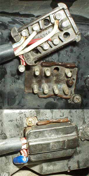
clic pic for thread
In fact, I need to do this to the '86. I have to run the fan on [1] all the time.
(The best way would probably be to rebuild/replace the blower motor, but hey!)
clic pic for thread
In fact, I need to do this to the '86. I have to run the fan on [1] all the time.
(The best way would probably be to rebuild/replace the blower motor, but hey!)
12-26-2006, 11:25 PM
#44
928 Barrister
Rennlist Member
Rennlist Member
I have been presuming that my problem is due to an intermittant overheating resistor pack. Here's what happens. If I am not above 45 mph (rare for me), my blower motor switches on to full for a few seconds every few minutes, and then shuts down. I thought it was because there was insufficient air flow over the resistor pack while in town, because it doesn't do it on the freeway. it pisses me off, because Dave A and I have already skinned our knuckles trying to replace the original with the one that's in there. Now I need to replace it also, I suppose, with a new one. I have all three blower speeds. Just this irritating high speed intermittant "on" that happens in town. Anyone ever get this gremlin??
12-26-2006, 11:28 PM
#45
Rennlist Member
Porken - (Or anyone) For us really, direction challanged folks, a little more obvious would help. I see what I assume is the after picture but no before picture. Has the lower left female recepticle been removed? I looked at the original thread but I'm still not clear? Am I correct in concluding that I can eliminate 'magic blower' and stop 0 fan speed by removing the lower right recepticle and moving the red wire and recepticle to the hole opposite its current position?