

A/c relay refreashing.
 04-15-2004, 07:14 PM
#1
Nordschleife Master
Thread Starter
I just pulled my a/c head unit apart.
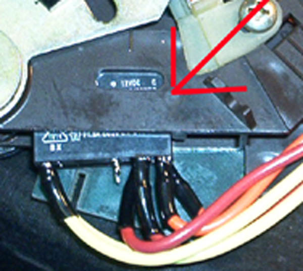
Boy is the relay for the a/c clutch cheap. Not only that, but the points on the relay were filty. I used a knife to clean the points off till they showed no resistance.
Anyways, I cleaned up the points. I'm a full 2+ volts higher at the a/c clutch now than I was before. As best as I can tell, this solves my slipping clutch problem.
That was a cheap repair.
 04-15-2004, 08:04 PM
#2
Addict
Lifetime Rennlist
Member
Lifetime Rennlist
Member
I thought the clutch was either engaged or not with the AC, and there is no way it can "slip?"
Also, in the trouble shooting Ive done in the past, I always saw good volts, I thought it was AMPERAGE that engaged the clutch?
If it works it works, you need it in HOU.

Also, in the trouble shooting Ive done in the past, I always saw good volts, I thought it was AMPERAGE that engaged the clutch?
If it works it works, you need it in HOU.
04-15-2004, 08:10 PM
#3
Nordschleife Master
Thread Starter
Sure it can slip. If the coil doesn't make enough force on the disk in the frount, there will not be enough friction between the disk and the pully. Not enough friction, and it slips.
The amount of force generated by the coil is a fuction of the amperage of current going through the coil. The more the amperage, the more force is generated.
Anyways, voltage and amperage are not independent concepts. They go together with resistance. IIRC, the formula goes
V/R = A
In otherwords, for a given resistance, to get a greater current flow, you need a higher voltage diffrence. We can not change the resistance of the coil, w/o screwing it up. Therefor if I can increase the voltage infront of the coil, the large amount of current I can push through the coil.
By reduceing the resistance in the relay, I increased the voltage infrount of the coil. And by doing this, I increased the flow of current through the coil, and hopefuly, am getting sufficent force to provide enough friction to keep the clutch engaged.
04-16-2004, 01:11 AM
#4
Rennlist Member
One thing worth remembering about relay contacts.... generally, filing them down should be considered a temporary fix, and the contact should be replaced in the short term. The contacts are basically little metal "buttons" which have a hard coating, like nickel alloys, while the bulk of the contact is a softer metal. The coating is particularly important when switching highly inductive loads as the arcing can foul and corrode the softer base metal surface relatively quickly.
That electromagnet is highly inductive(has to be) and as the magnetic field collapses across the winding on deactivation it will cause a current flow that results in the arcing.
That electromagnet is highly inductive(has to be) and as the magnetic field collapses across the winding on deactivation it will cause a current flow that results in the arcing.
04-16-2004, 11:20 AM
#5
Nordschleife Master
Thread Starter
That leads me to a question.
How do you replace the contact points? Can it be done independently from the relay or do I need to source a new relay. I've never seen one quite like this one, so I don't think I could find an exact match.
How do you replace the contact points? Can it be done independently from the relay or do I need to source a new relay. I've never seen one quite like this one, so I don't think I could find an exact match.
04-16-2004, 11:54 AM
#6
Chronic Tool Dropper
Lifetime Rennlist
Member
Lifetime Rennlist
Member

Originally posted by ViribusUnits
That leads me to a question.
How do you replace the contact points? Can it be done independently from the relay or do I need to source a new relay. I've never seen one quite like this one, so I don't think I could find an exact match.
That leads me to a question.
How do you replace the contact points? Can it be done independently from the relay or do I need to source a new relay. I've never seen one quite like this one, so I don't think I could find an exact match.
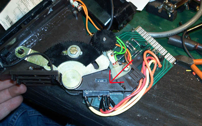
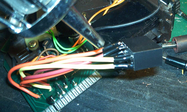
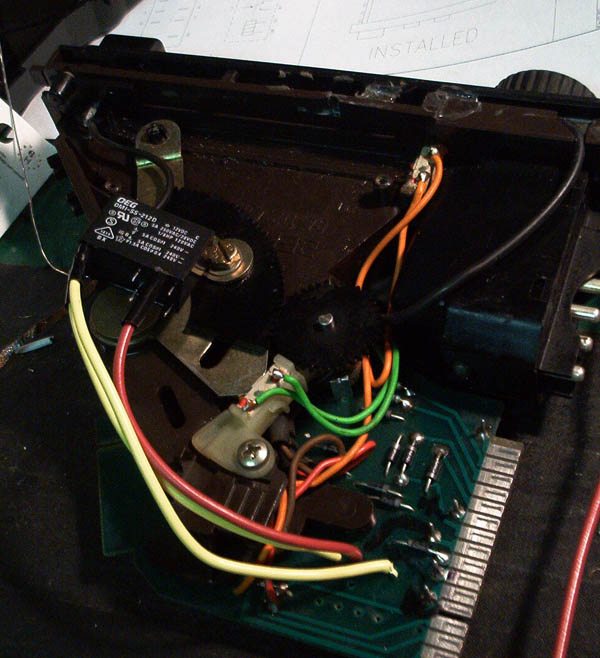
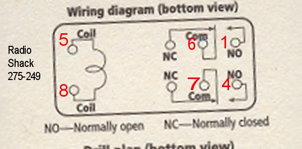
I did a drawing/instruction on relplacing the control-head relay with an external one. In the last couple weeks, several listers have done this surgery themselves using a commonly-available Radio Shack relay. Part number for that is 275-218 at Radio Shack stores, for a DPDT relay with contacts rated for 10 amps and 24VDC, and a max contact voltage of 125VDC. The installation is external to the case. I used some double-stick tape to hold the little relay to the right side of the controller, so it still slides into the console. e-mail me at dr.bobf[at]att.net if you would like a copy, or grab it off og Greg Nichols' tips page. The drawing shows a different relay, so if you want to use the R-S part, you'll need to adjust the wire connections on the relay for the different contact/pin connections.
If you have the drawing, you can use the R-S relay by making the following mods:
My wire number 1 connects to your relay terminal 4
My wire number 4 connects to your relay terminal 3
My wire number 5 connects to your relay terminal 7
My wire number 6 connects to your relay terminal 6
My wire number 7 connects to your relay terminal 5
My wire number 8 connects to your relay terminal 8
I'll probably do a re-write of that instruction, with pictures, when I get a suitable candidate car here for the fix at a future SoCal928 tech session.
E-mail me if you'd like a copy of the drawing directly.
Trending Topics
 04-17-2004, 09:17 AM
#9
Addict
Rennlist Member
Rennlist Member
Ok,
I'm about to pull my head unit as well to do some bulb replacement/upgrades. Doe the manual HVAC unit (78-79) have this relay as well, or is it only on the auto climate control head units on the later models??
I'm about to pull my head unit as well to do some bulb replacement/upgrades. Doe the manual HVAC unit (78-79) have this relay as well, or is it only on the auto climate control head units on the later models??
04-17-2004, 01:11 PM
#10
Chronic Tool Dropper
Lifetime Rennlist
Member
Lifetime Rennlist
Member
Greg--
Nice job, and GREAT pictures.
What is the voltage/current rating on those relay contacts? I looked at several options when I did mine, and no in-stock R-S relays were small enough .and. rated well enough to endure the clutch circuit abuse. If yours is rated at 6A or better, we have a new winner!
Nice job, and GREAT pictures.
What is the voltage/current rating on those relay contacts? I looked at several options when I did mine, and no in-stock R-S relays were small enough .and. rated well enough to endure the clutch circuit abuse. If yours is rated at 6A or better, we have a new winner!
04-17-2004, 06:45 PM
#11
Three Wheelin'
Dr. Bob,
Thanks!
5 amp at 240vac / 24vdc.
The stock Gruner relay which is no longer available through Gruner is (was) 2.5 / 250vac.
The draw in the as listed on the A/C clutch is 3.5 amp.
I'm OK with this 5 amp untill either it gives me a problem (which I doubt it will) or when something better comes along.
here is a pic of the original Gruner
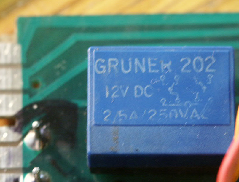
Greg
Thanks!
5 amp at 240vac / 24vdc.
The stock Gruner relay which is no longer available through Gruner is (was) 2.5 / 250vac.
The draw in the as listed on the A/C clutch is 3.5 amp.
I'm OK with this 5 amp untill either it gives me a problem (which I doubt it will) or when something better comes along.
here is a pic of the original Gruner
Greg
04-27-2004, 12:49 PM
#12
Rennlist Member
Dr. Bob wrote:
Do these instructions relate to this R-S relay? (275-218)

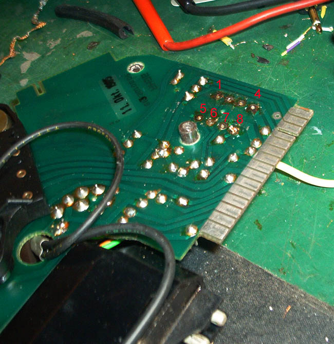
And are Dr. Bob's "my wire number" designations the same as the IC board designations (1,4,5,6,7,8) in Greg86andahalf's pic above?
Thanks for the clarification. I went to the Nichols sight and couldn't get the diagram/instructions to print out.
If you have the drawing, you can use the R-S relay by making the following mods:
My wire number 1 connects to your relay terminal 4
My wire number 4 connects to your relay terminal 3
My wire number 5 connects to your relay terminal 7
My wire number 6 connects to your relay terminal 6
My wire number 7 connects to your relay terminal 5
My wire number 8 connects to your relay terminal 8
Do these instructions relate to this R-S relay? (275-218)
And are Dr. Bob's "my wire number" designations the same as the IC board designations (1,4,5,6,7,8) in Greg86andahalf's pic above?
Thanks for the clarification. I went to the Nichols sight and couldn't get the diagram/instructions to print out.
04-27-2004, 02:52 PM
#13
Rennlist Member
Two (somewhat) related points:
If the AC controller is still in good condition, then rather than 'fixing' it,
a) install a 10-20-30 amp standard SPST relay on the compressor supply line as suggested by Joel F - and pick up (fused) power from the B+ post under the hood. ie., the controler is only switching a relay - pretty light duty service.
b) or protect the existing controller relay by installing a diode(s?) as dr bob notes
Regards Joel's comment, Walley noted adding a diode to assure the operation of the electric fan in earlier cars: good point, but where to install (circuit diag)?
Second question, if protective diodes would help preserve the controller, in which lead and direction should it/they be inserted in the controller? or again,could one be added to the compressor clutch feed line (size)?
06-20-2004, 05:29 PM
#14
Under the Lift
Lifetime Rennlist
Member
Lifetime Rennlist
Member
Originally posted by atb
Do these instructions relate to this R-S relay? (275-218)
And are Dr. Bob's "my wire number" designations the same as the IC board designations (1,4,5,6,7,8) in Greg86andahalf's pic above?
Thanks for the clarification. I went to the Nichols sight and couldn't get the diagram/instructions to print out.
