When you click on links to various merchants on this site and make a purchase, this can result in this site earning a commission. Affiliate programs and affiliations include, but are not limited to, the eBay Partner Network.
The 28mm lasted a little while, snapped at the usual location we are used to seeing.
The 25mm was rifle drilled in steps. 3/16 9", 1/4 6" deep both ends. Extra bearings installed (4-5 total he's not sure) with the balancer removed. He did note some harmonics at a certain RPM that were not present before.
This shaft did not fail in the traditional way. It never separated, the car was still driveable. The shaft looked like a tree branch twisted. He thought something broke in the transmission the way it felt when accelerating.
In his opinion, the stock shaft is strong enough if it were properly heat treated. He tested one and on the rockwell hardness scale is very low.
He doesn't have the specs of the DOM steel tube used for the new one in front of him. When he digs those up he'll let me know.
The video of his car turning the 10sec @ 150mph in the 1/4 was with the rifled drilled 25mm shaft.
The stock 25mm driveshaft seems to be a strong piece. It should be and probably is heat treated like a spring. For it to be as durable as possible, it should deform or spring by the exact same amount at each point. It would be an interesting little engineering math problem to figure out exactly how it should be gun drilled to make it equally stressed everywhere.
More bearing supports is definitely helpful at higher rpms. I don't think they do as much to help with additional torque, provided that the shaft critical rpm is above the actual engine rpm.
By "harmonics" you mean in cabin noise and vibration?
It would be an interesting little engineering math problem to figure out exactly how it should be gun drilled to make it equally stressed everywhere.
He looked into gun drilling one all the way through, but again switched gears to the new drive shaft design / flywheel / starter relocation instead.
Originally Posted by ptuomov
By "harmonics" you mean in cabin noise and vibration?
Noise maybe like a hum, comparable to a custom exhaust when you get a droning sound. It seemed to go away at higher RPM's. Only noticed it at low RPM's when cruising around, nothing at idle. He did note the additional noises at higher RPM could have been masking it.
Only under load, revving it in neutral did not cause it.
He did not notice any vibration like mirror shake or something else you could notice or feel.
That's consistent with the stock torque tube vibration damper being there to reduce cabin noise at the frequency at which the external tube (with engine and tranny in the ends of that Eifel tower) resonates, which peaks at about 3300 rpm for automatic cars.
One more little note. Basic engineering math says that if weight is not a consideration, then a solid shaft is stronger under torsion than a hollow shaft of the same outside diameter. It's just that the weight is used less efficiently close to the shaft centerline. Gun drilling the stock shaft should therefore be expected to make the shaft weaker, not stronger. There's a minor caveat that gun drilling a very small diameter hole at the centerline of the shaft may in fact release and reduce some stresses. Therefore, with very small ID holes, the gun drilled shaft in some cases may be a tiny bit stronger than a solid shaft of the same OD. Just noting this before everyone who's ever broken a shaft is running to get theirs drilled.
Some people have raised questions about air flow to the radiator. Any thoughts about that? Any ideas for improving it, given the space constraints? The electric fan idea was already mentioned.
Move the radiator to behind DS rear wheel fender well cover, add a fan?
For that to work, I'd have to cut another hole into the fender to vent in fresh air. I'd much rather not modify the exterior if I can avoid that.
There are other options for improving cooling in general with additional vents. For example, hood vents like in the Porsche 968 Turbo cars. Holding back for now, though, trying to avoid it.
One thing I've been thinking about is adding a triangle shaped plate between the exhaust heat shields with a NACA duct in it. The big NACA duct could them be connected tot he heat exchanger.
One thing I've been thinking about is adding a triangle shaped plate between the exhaust heat shields with a NACA duct in it. The big NACA duct could them be connected tot he heat exchanger.
Nothing except turbulence under there no? If using both front and cat under trays, NACA duct immediately after metal cat under tray might get almost-smooth flow for NACA duct?
For that to work, I'd have to cut another hole into the fender to vent in fresh air. I'd much rather not modify the exterior if I can avoid that.
There are other options for improving cooling in general with additional vents. For example, hood vents like in the Porsche 968 Turbo cars. Holding back for now, though, trying to avoid it.
One thing I've been thinking about is adding a triangle shaped plate between the exhaust heat shields with a NACA duct in it. The big NACA duct could them be connected tot he heat exchanger.
Originally Posted by worf928
Nothing except turbulence under there no? If using both front and cat under trays, NACA duct immediately after metal cat under tray might get almost-smooth flow for NACA duct?
Tuomo, just don't forget the discussion you, I and Mark K. had about NACA ducts. Since they plunge under the surface they require a pressure differential across the inlet and outlet in order for air to flow through them. Because this is a ram air situation, a well conceived scoop will provide better flow diversion. Another concern is the blockage of airflow behind the heat exchanger by the transmission itself.
Some people have raised questions about air flow to the radiator. Any thoughts about that? Any ideas for improving it, given the space constraints? The electric fan idea was already mentioned.
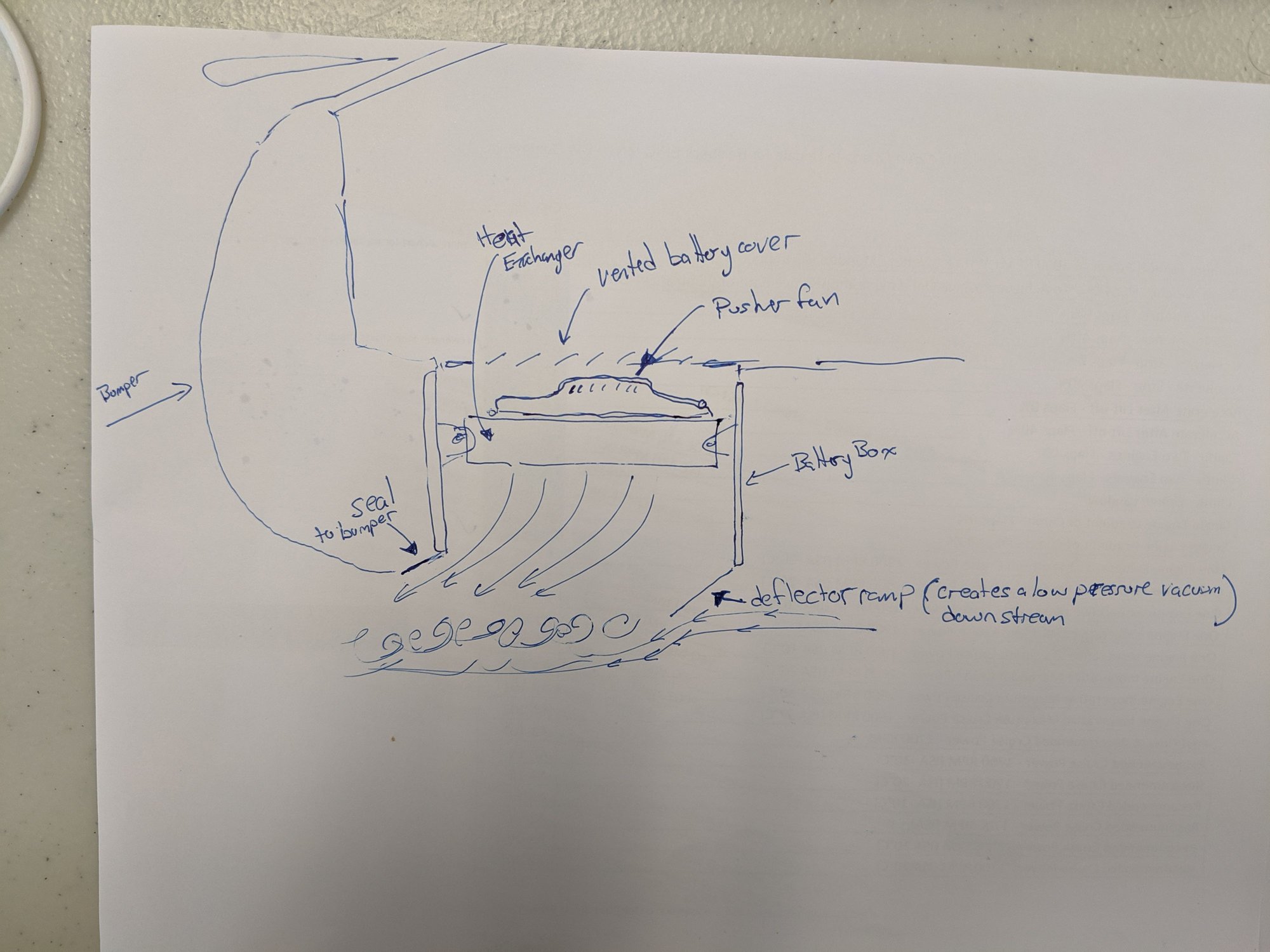
OK here is a suggestion for an alternate placement. It will however require you to re-position your battery in the rear hatch somewhere. Maybe remove the tire and mount the battery to the side of the tire well. Also either remove or vent the battery cover. This is one way to get clean fresh air with good flow through the heat exchanger. Please excuse the crude sketch.
Nate: Cabin air passes through the battery box lid?
I think you'd want to relocate the fuel tank to somewhere well clear of the new draft chute into the cabin if you choose the cabin as the cooling-air source.
Tuomo, I don't know how much if any room you have left in the wheelhouse areas front or rear. Temptation would be to plumb towards one of the rears, likely the right side away from the exhaust outlet, and draw wheelhouse air through the cooler to vent under the rear bumper shell. This would put some fragile pieces (cooler and fan) behind the beam, but safer from normal road debris than having it so close to the ground in front. of the gearbox case.
OK here is a suggestion for an alternate placement. It will however require you to re-position your battery in the rear hatch somewhere. Maybe remove the tire and mount the battery to the side of the tire well. Also either remove or vent the battery cover. This is one way to get clean fresh air with good flow through the heat exchanger. Please excuse the crude sketch.
I like it! Clever idea.
This would require some testing, to make sure that the ventilation through the box was venting into a low pressure area....so that when the fan was off, there were no fumes coming into the car.
You could "vent" the air out the driver's side of the box (towards the muffler), keeping any heat away from the fuel tank, which would eliminate what Dr. Bob is concerned about.
Out of the box thinking, for sure. One issue is that the heat exchanger will be running hot and heating any air that goes thru it. Therefore, any air that goes thru will naturally want to raise up instead of going down. A second issue is that a puller fan with a shroud is more efficient than a pusher fan. A third issue is that I don't like having an open gas path from so close to the exhaust pipes into the passenger compartment, as any exhaust leaks could get into the cabin when the pusher fan is not running.
Just placing a scoop in front and the puller fan in the back of the current placement in the earlier photo would move a lot of air without having to go into the passenger compartment. There's a natural exit path for air on both sides of the transmission.
Originally Posted by GT6ixer
OK here is a suggestion for an alternate placement. It will however require you to re-position your battery in the rear hatch somewhere. Maybe remove the tire and mount the battery to the side of the tire well. Also either remove or vent the battery cover. This is one way to get clean fresh air with good flow through the heat exchanger. Please excuse the crude sketch.
Nate: Cabin air passes through the battery box lid?
I think you'd want to relocate the fuel tank to somewhere well clear of the new draft chute into the cabin if you choose the cabin as the cooling-air source.
Tuomo, I don't know how much if any room you have left in the wheelhouse areas front or rear. Temptation would be to plumb towards one of the rears, likely the right side away from the exhaust outlet, and draw wheelhouse air through the cooler to vent under the rear bumper shell. This would put some fragile pieces (cooler and fan) behind the beam, but safer from normal road debris than having it so close to the ground in front. of the gearbox case.
Originally Posted by GregBBRD
I like it! Clever idea.
This would require some testing, to make sure that the ventilation through the box was venting into a low pressure area....so that when the fan was off, there were no fumes coming into the car.
You could "vent" the air out the driver's side of the box (towards the muffler), keeping any heat away from the fuel tank, which would eliminate what Dr. Bob is concerned about.
Originally Posted by ptuomov
Out of the box thinking, for sure. One issue is that the heat exchanger will be running hot and heating any air that goes thru it. Therefore, any air that goes thru will naturally want to raise up instead of going down. A second issue is that a puller fan with a shroud is more efficient than a pusher fan. A third issue is that I don't like having an open gas path from so close to the exhaust pipes into the passenger compartment, as any exhaust leaks could get into the cabin when the pusher fan is not running.
Just placing a scoop in front and the puller fan in the back of the current placement in the earlier photo would move a lot of air without having to go into the passenger compartment. There's a natural exit path for air on both sides of the transmission.
Good counterpoints all. A combination of all ideas may work. That being a puller fan with a shroud under the HE in the battery box. Bring in high pressure cold air from the PS wheel arch by opening a hole in the top of the arch from inside the cabin and build a sealed air duct from there into the top of the battery box, This way it is a closed system with no chance of exhaust gasses getting into the cabin.
Tuomo, the two issues with you current placement could be, 1. the amount of physical airflow blockage behind the HE in that location and 2. the relative warm air from the exhaust pipe that would be fed into the scoop. However it may work, you just have to test it. My modified suggestion likely would work, but definitely not as tidy.
Replicating the basic design of the front under tray (louvers for venturi effect and a NACA duct) and running one down each side of the underbody so as to avoid the center-run exhaust would result in two streams of cool(-ish) air. Some odd cross-section ducting between the underbody and under tray could then route that air.
Replicating the basic design of the front under tray (louvers for venturi effect and a NACA duct) and running one down each side of the underbody so as to avoid the center-run exhaust would result in two streams of cool(-ish) air. Some odd cross-section ducting between the underbody and under tray could then route that air.
Do you think that exhaust heating the air will be that significant? The exhaust gas seems to lose about 25% of the temperature differential between exhaust gas and the outside air for each meter of exhaust piping. I'm guesstimating about 600F inside the pipe towards the end of the "infinity pipe". So it will heat the air somewhat, but how much? At speed, there's going to be a lot of air flow under the car.
If the specific heat of oil is about 2 kJ/(kg*K), if the pump is pumping 200 kg/h, and if I want to drop the oil temperature by 30K, then I need to remove 2*200*30 = 12 MJ/hour. That's about 3.5 kW or 12,000 BTU/h that I want to take out of the oil to cool the gears. With air having a specific heat of about 1 kJ/(kg*K), I need 12,000 kg*K/h of air flow. That is, 12,000/h kg of air flow with 1C = 1K temperature increase or 600 kg/h of air with 20C temperature increase. 600kg/h is about 300 CFM at those temperatures, so that's what the air flow would need to be if the temperature increase is 20C. Did I make a math mistake there?


 06-27-2019, 12:36 PM