When you click on links to various merchants on this site and make a purchase, this can result in this site earning a commission. Affiliate programs and affiliations include, but are not limited to, the eBay Partner Network.
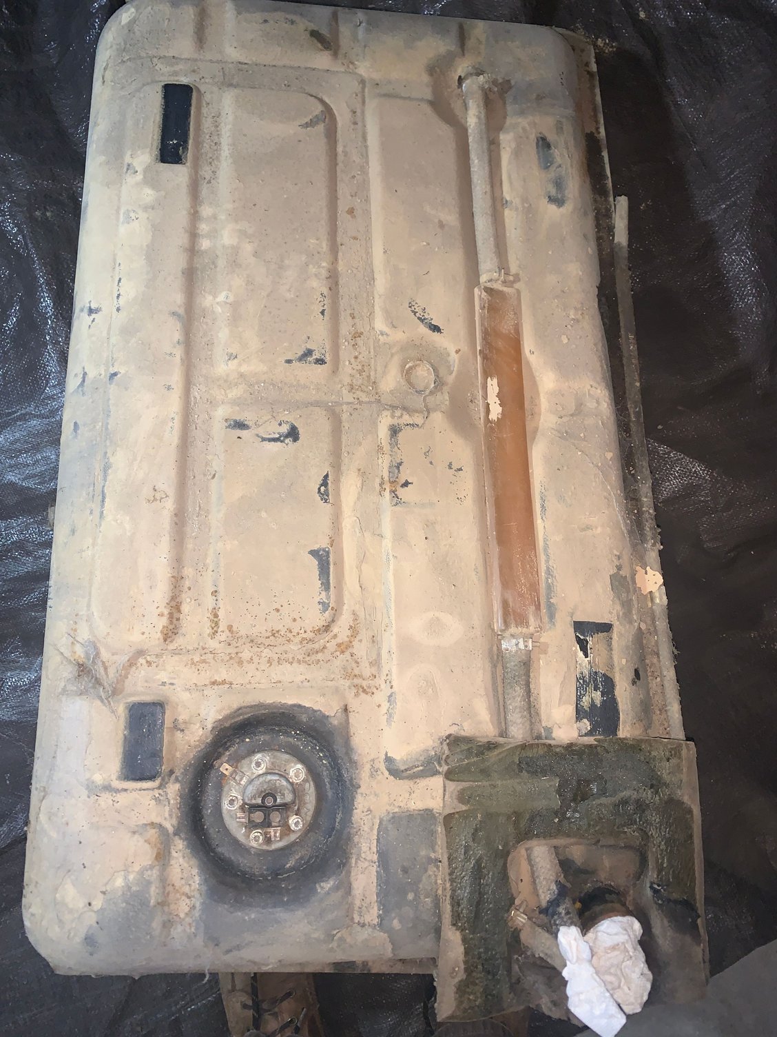
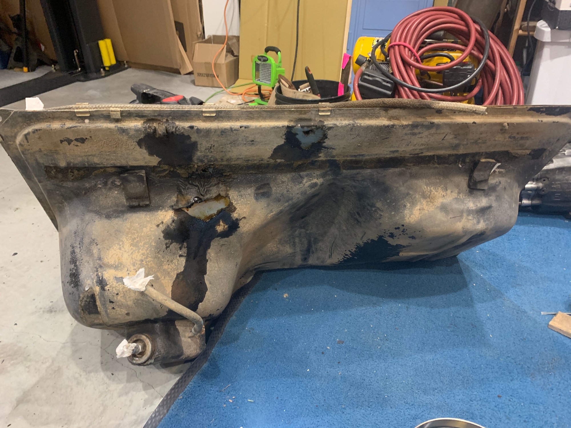
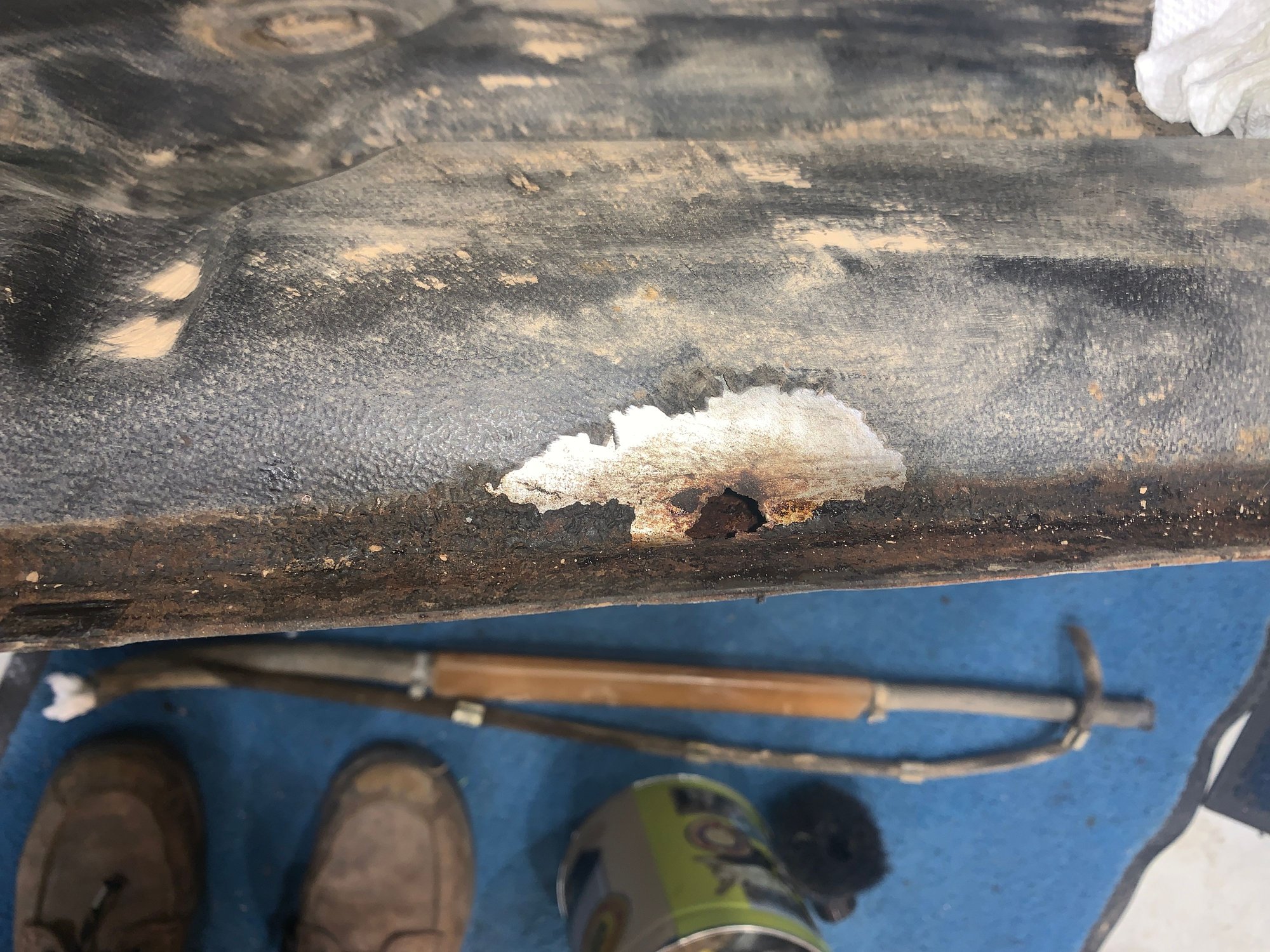
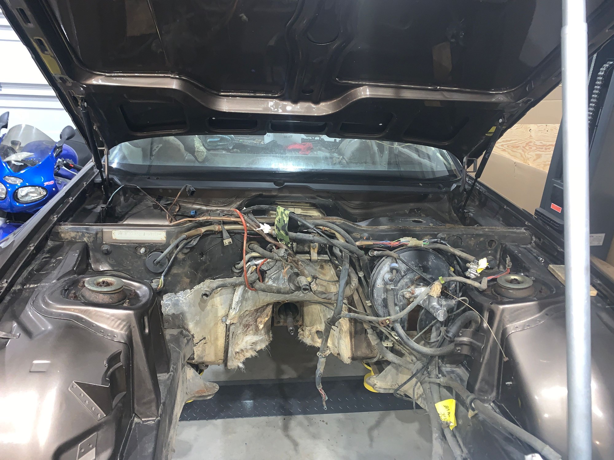
OK , heres some updates on the project, I got the tank out a while ago and it is in very bad shape. It was covered with the same dusty dirt that the transaxle was covered in. Lots of holes along the front edge. There were blistered sacks of sticky brown goo in the black undercoating type paint on the tank. It also feels like it has about 10lbs of rust and crap rolling around inside of it. I'm looking online at junkyards close to my area and I have found a few yards that have early cars. Made some calls and they are looking at the tanks to see what kind of shape they're in. We'll see what happens.
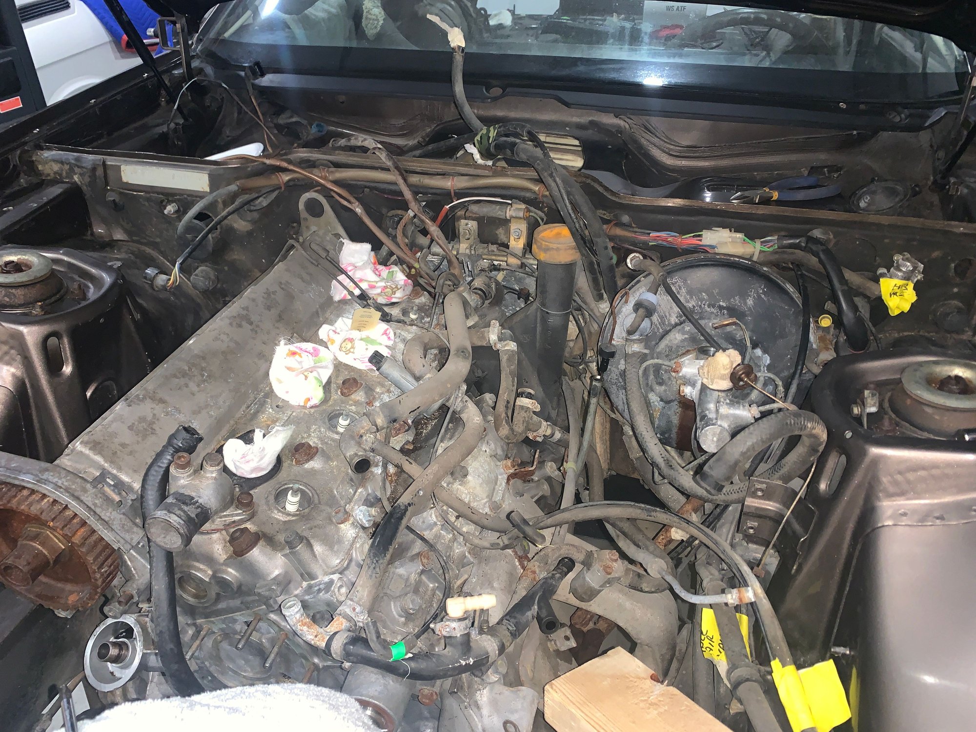
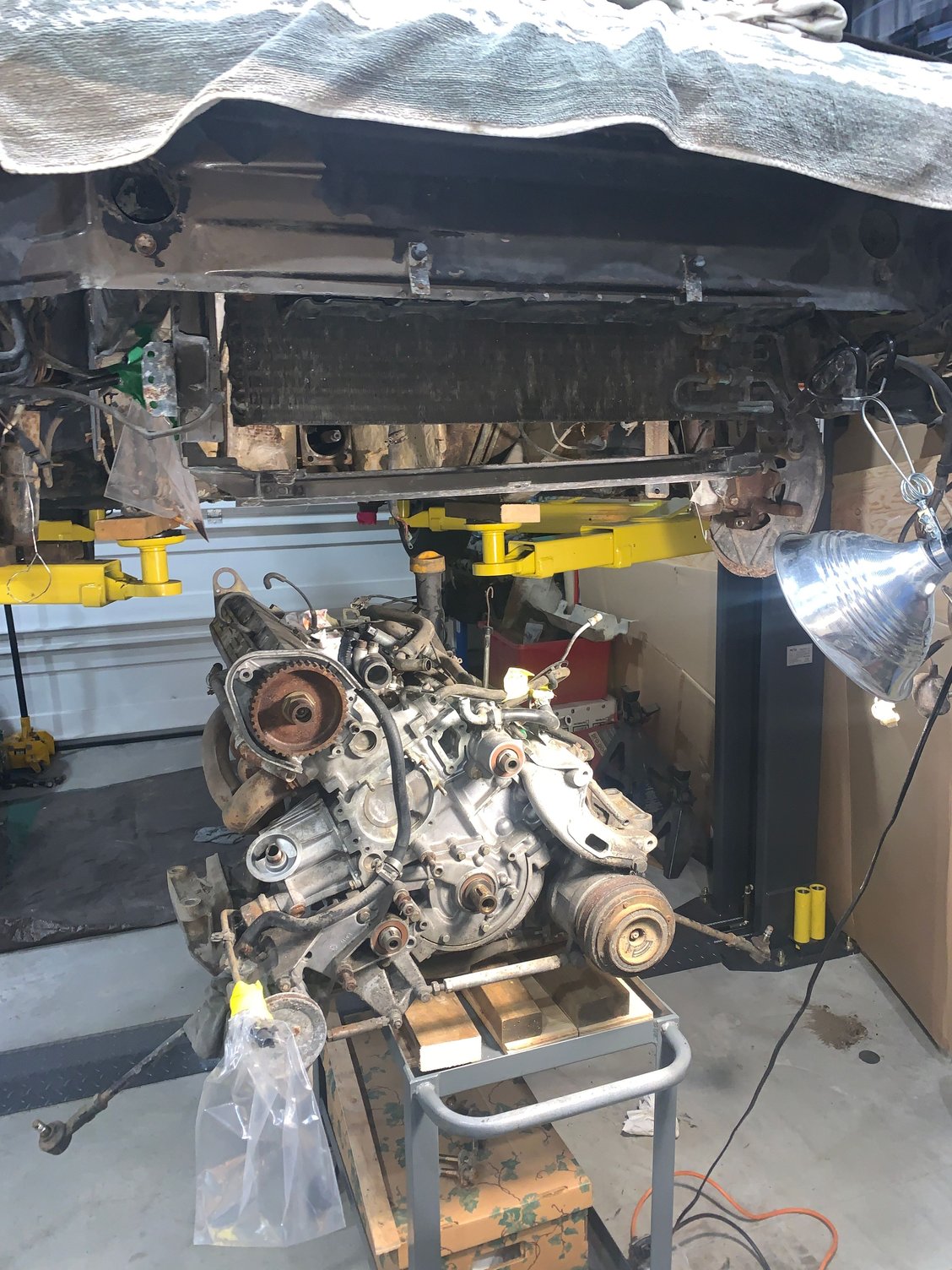
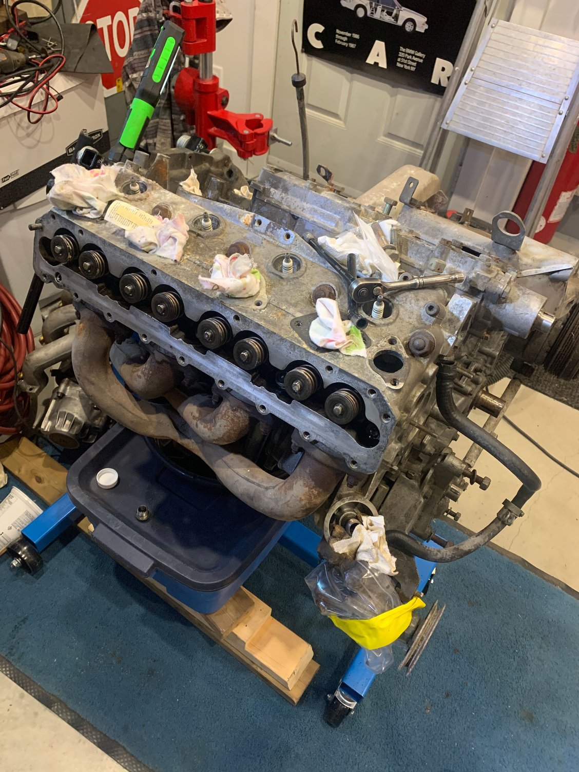
I'm also working at disconnecting everything on the engine , getting ready to remove it. I'm planning on unbolting the torque tube and sliding it back enough to drop the engine. I'm hoping to just leave the TT in place for now until I remove the rear subframe. Hope that works. I ended up taking off the fuel rail and the intake to get access to some of the vacuum hoses, coolant hoses, wires etc etc. Amazing how many connecting there are all packed under there and at the back of the engine. Nothing looks in very good shape. I know some of these hoses are $$$$ Lots of pictures taken, hope I can get this back together in a year or more
Last edited by maybeillbuyit; 01-29-2022 at 02:21 PM.
Reason: added info
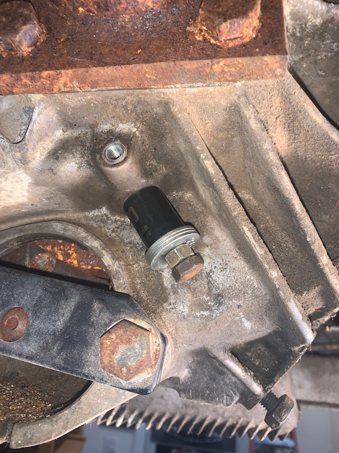
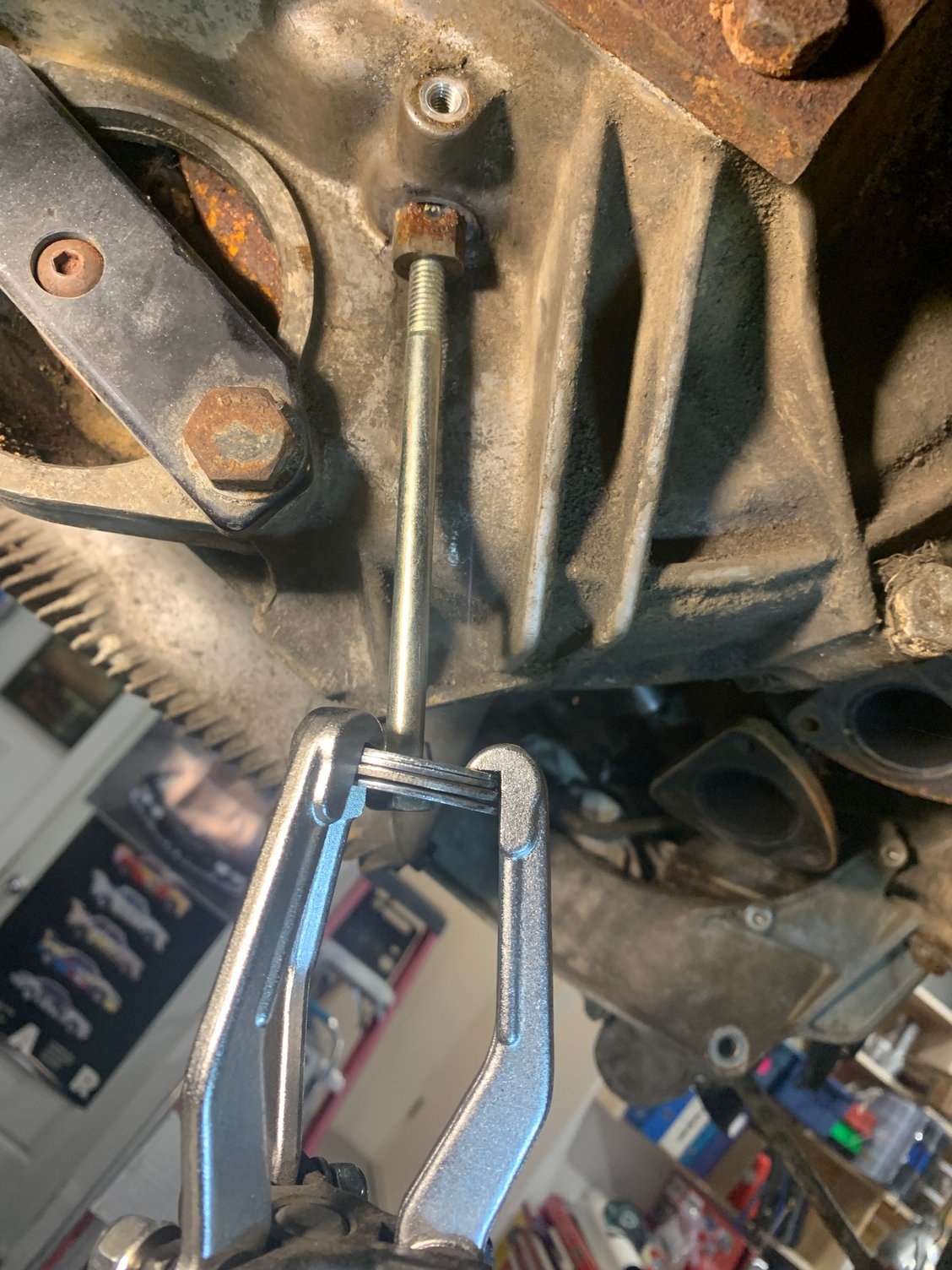
OK , on to the next problem. I knew this wasn't going to be an easy one. The clutch fork cross shaft needs to come out. I tried making a little puller with a socket and nut and bolt. It worked a little bit. I managed to get it out almost an 1/8 LOL. I gave up with that , I was afraid the bolt would snap off. I sprayed PB in there to try to lube it up. I see on Comeau's videos its possible to get a screwdriver in from the other side and hammer it out. I may try that. I also have a slide hammer but no way to connect it to the 8mm threads in the shaft. I'll try again today. Lots of rust in there, I hope that flywheel is saveable.
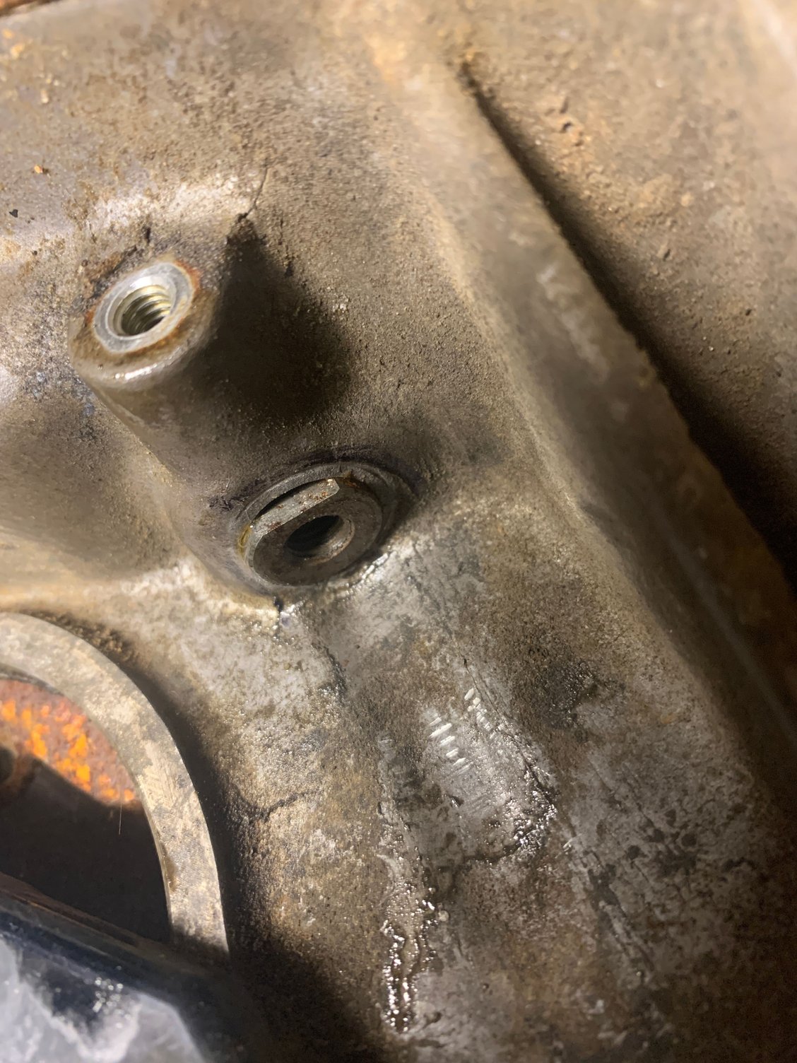
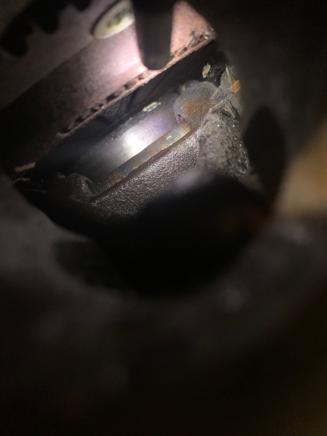
Not a very good pic here but you can see the shaft has a bunch of rust all over it. Going to be tough to hammer that through the hole
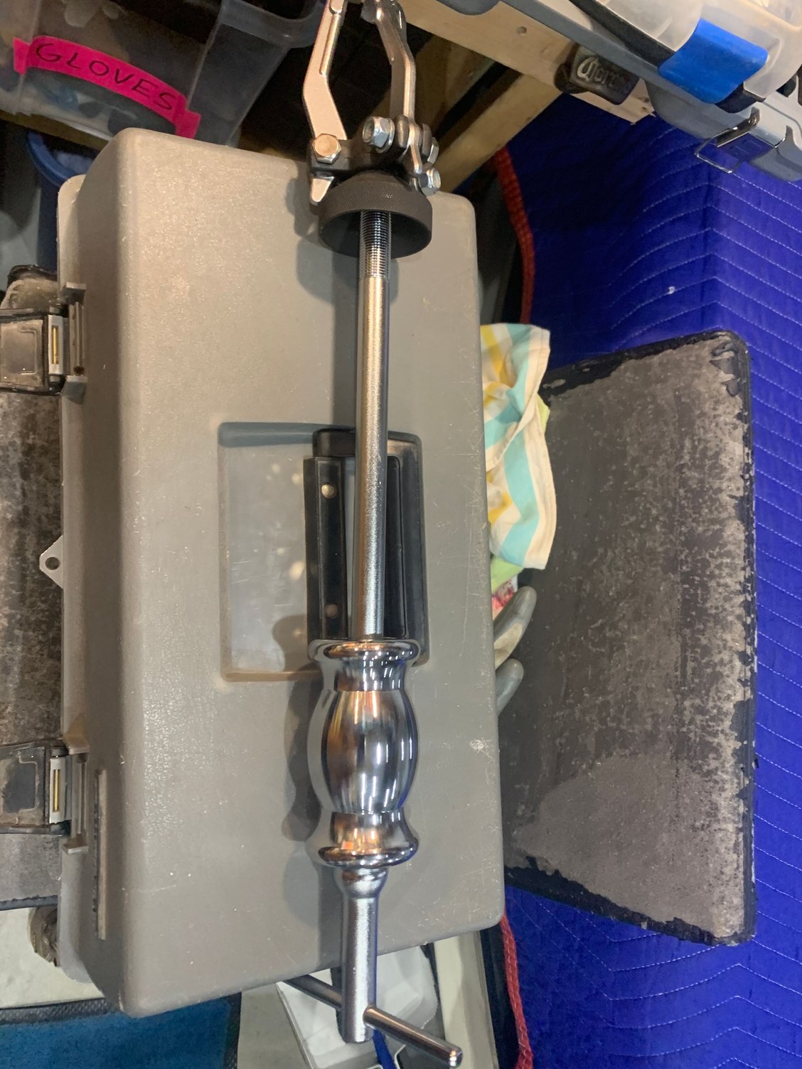
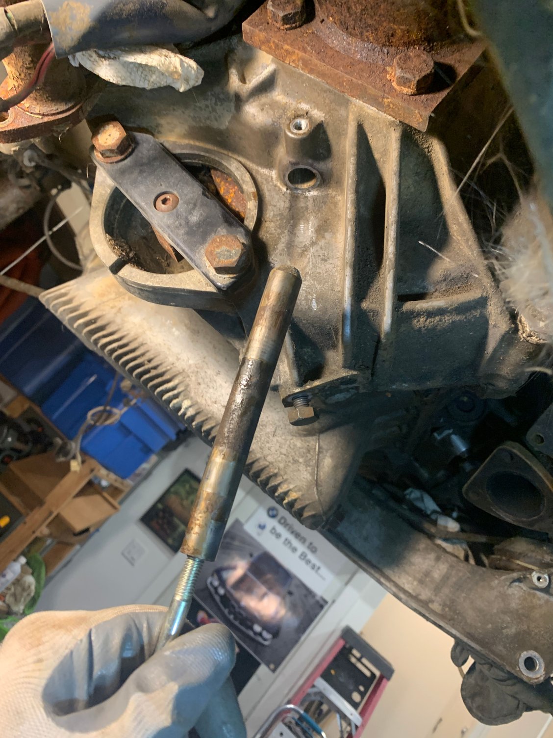
Well I gave that clutch fork shaft what for today. I finally got some use out of my slide hammer. Its never really fit or worked out for anything I've wanted to use it for. Some big washers on the end of a long 8mm bolt and about 5-10 minutes of good solid pounding that hammer and it surrendered. I hope that fluffy disintegrating insulation in the bellhousing tunnel area isn't asbestos? It looks like fiberglass . Definitely getting rid of ,and replacing that mess.
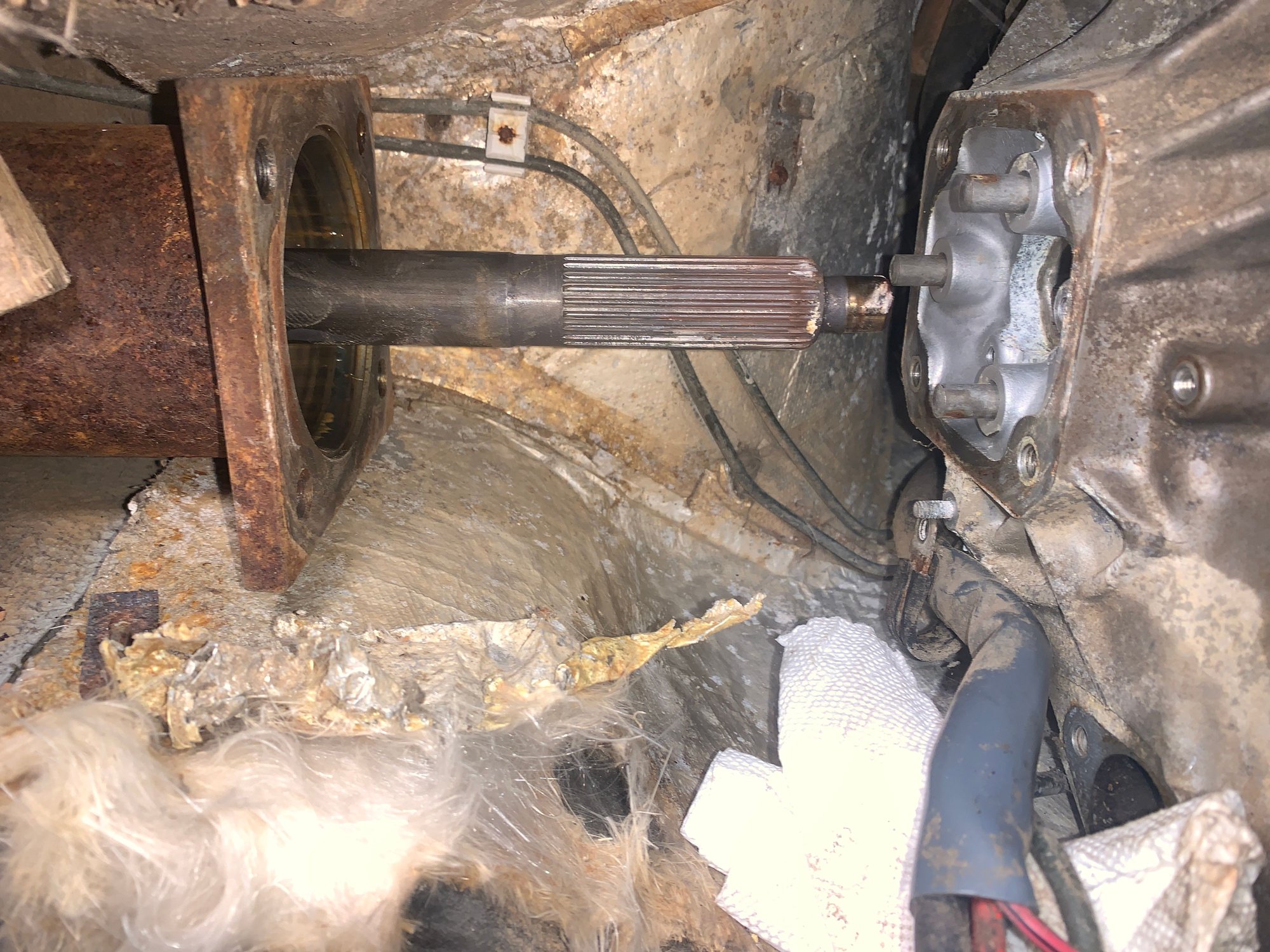
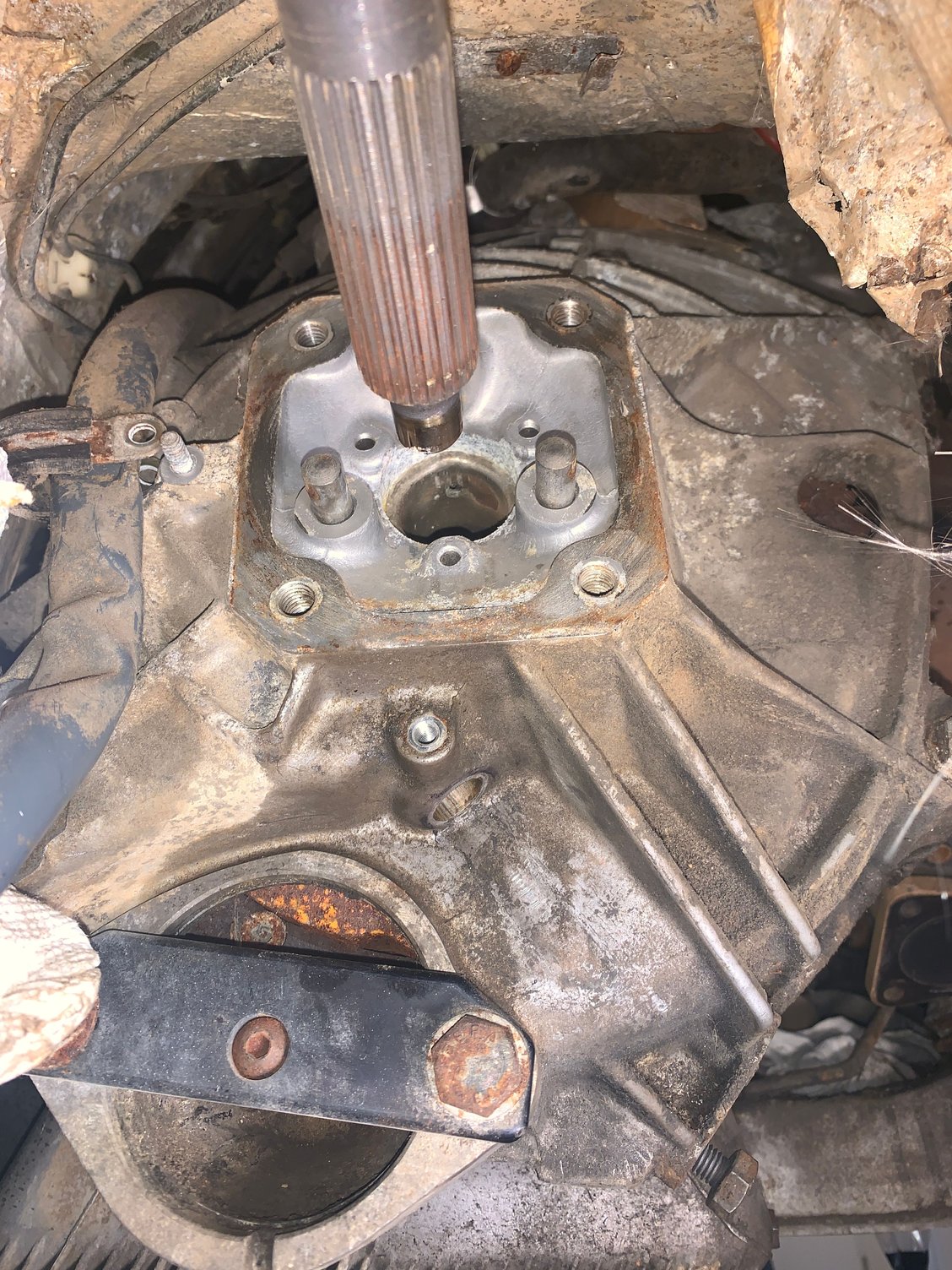
After that I unbolted the 4 big bolts holding the torque tube to the bellhousing, I was expecting more rusty ,stuck ,don't wanna cooperate BS but it slid right back and rested on the crossmember bracket things. Its spins fairly smoothly, not silent but no grinding or nasty sounds. And thankfully the "nub" looks pretty good but I'll have to measure that.
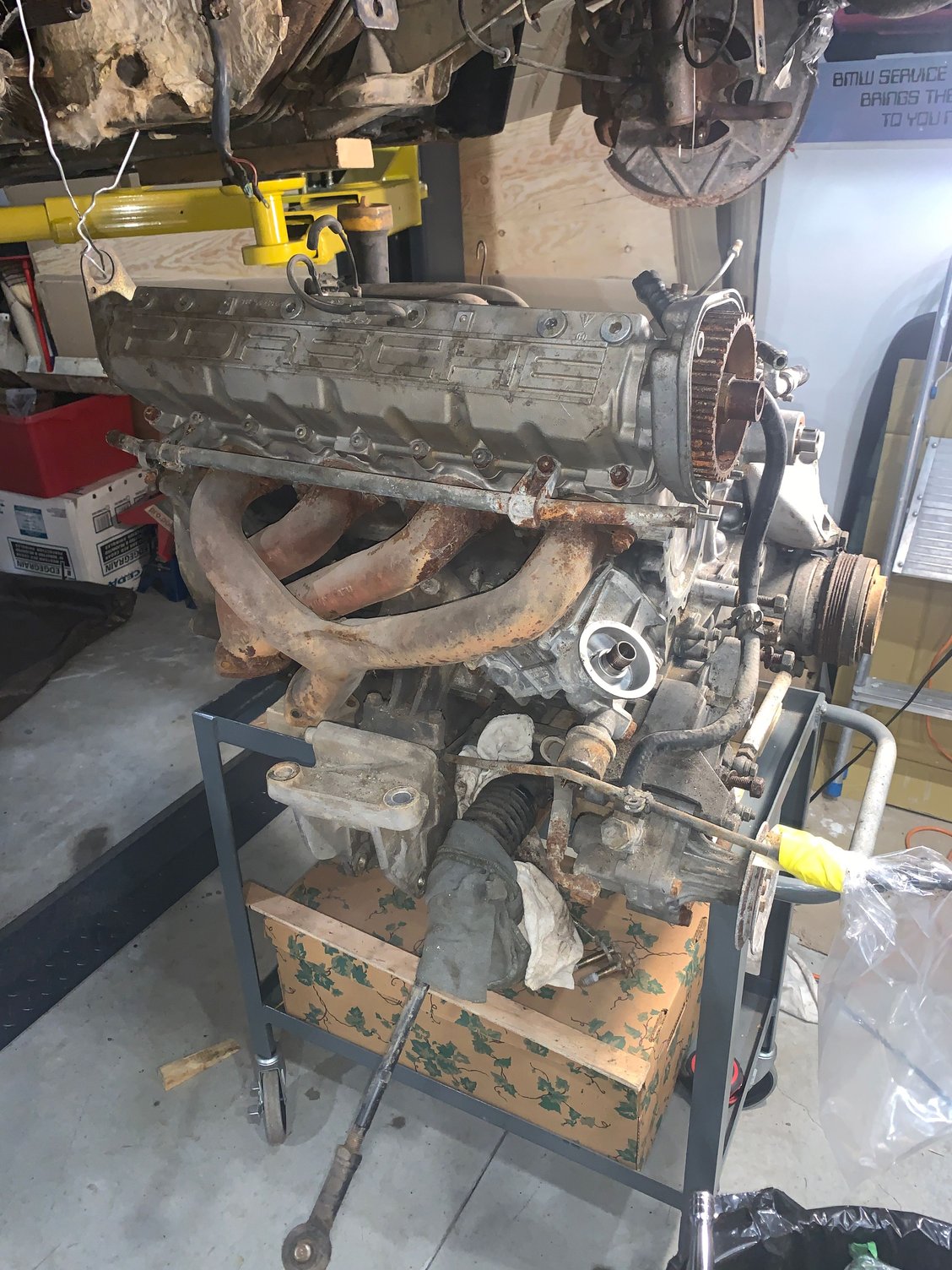
And then 4 bolts and the engine is out on the rolling cart. After all the trouble with the transaxle connector, then the clutch fork it was surprising trouble free getting the engine out. I'm really loving the lift. Next I need to get this greasy lump onto an engine stand.
Last edited by maybeillbuyit; 01-31-2022 at 12:59 AM.
Reason: added info
NICE!
So, you probably don't want to hear this but... for future reference, the way you removed the engine, separating the torque tube from the bell housing, the clutch arm pivot shaft does not need to be removed first.
NICE!
So, you probably don't want to hear this but... for future reference, the way you removed the engine, separating the torque tube from the bell housing, the clutch arm pivot shaft does not need to be removed first.
Haha. Hilarious! I wondered why it needed doing a couple times. I guess just watching the videos of doing a clutch replacement I assumed it was a step that needed doing. Too bad as I could have got that engine out sooner and just worried about the pivot shaft later. Well stay tuned , theres more wrong turns coming on this project. I'm usually pretty good at researching what I'm doing but for me this is such a big ( for me) project I feel like I'm just diving in without checking. Maybe I'll slow down a bit and be more careful. I'm usually not one to be asking too many questions on the forums as I know it gets tedious for those in the know to answering the same quires over and over. Thx very much Gage, I do appreciate comments and advise. So i'm wondering now that I have the engine out. I'll remove the clutch/flywheel, then the head. With out the flywheel lock on things may move, but that won't be a problem as I'll be putting everything back into time during the rebuild, correct?
Once the cam housing is off, the valves will all be closed and protected from untimed piston interference. There are also many ways to lock the flywheel against turning (say to remove pressure plate or flywheel bolts) after the bell housing is off by wedging between various bolts installed in the flywheel and block.
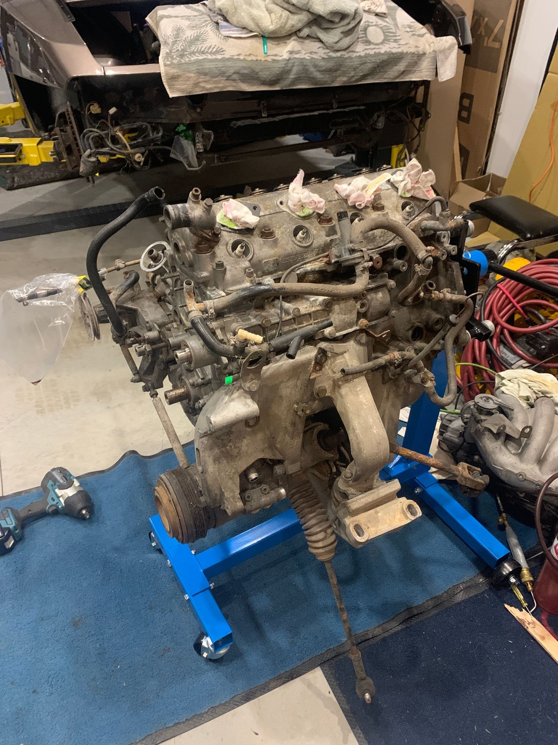
I got the engine on the stand. and the cam housing and accessories, wires etc stripped off. Lots of pics taken and most items bagged and tagged
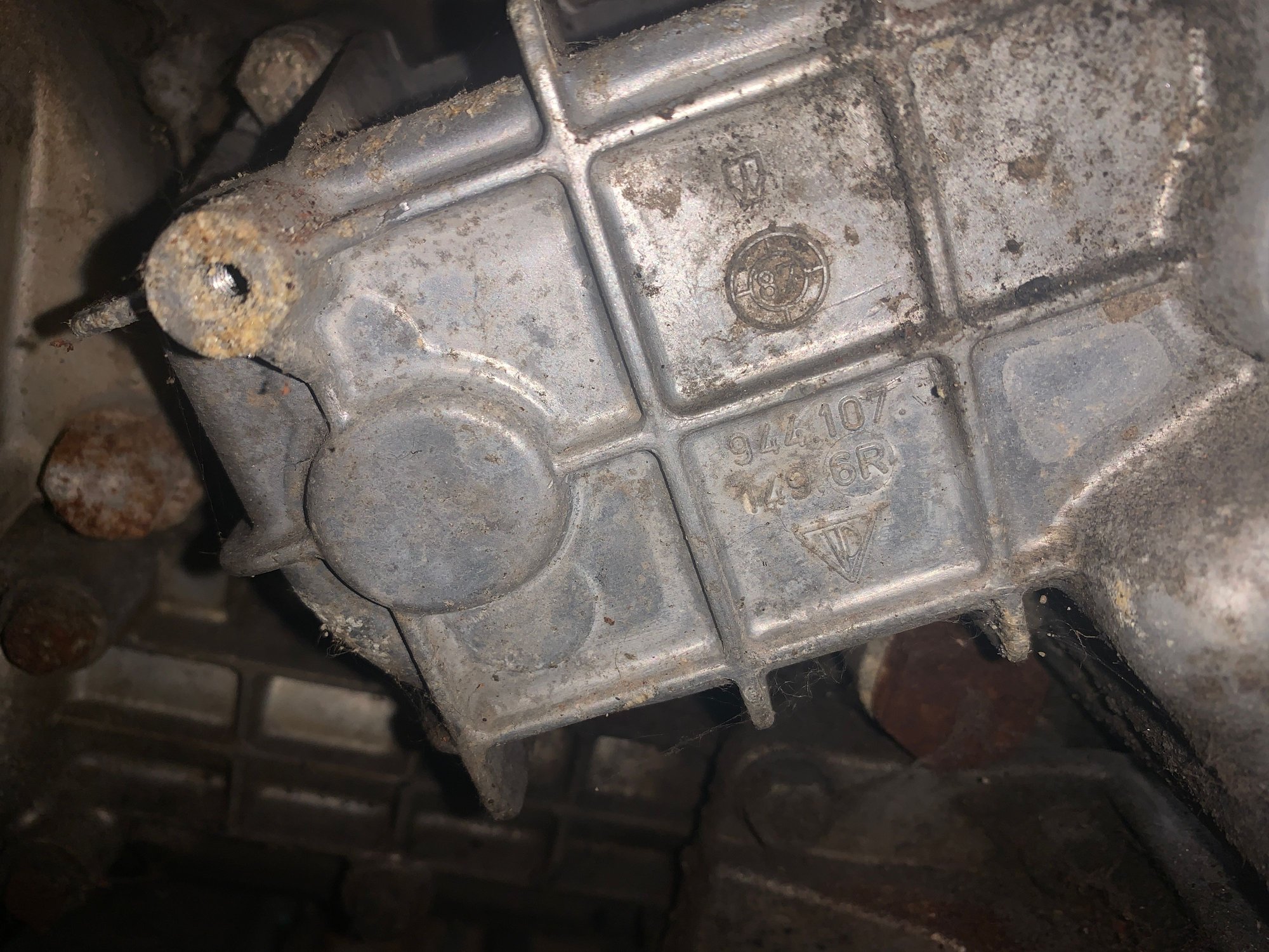
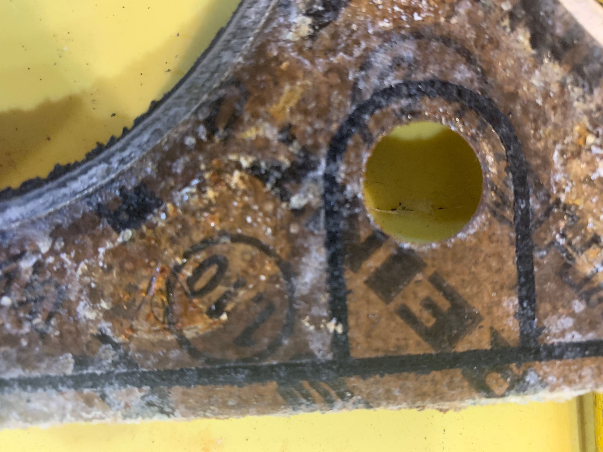
I was happy to see the 6R and 87 manufacture date. I assume this is the correct upgraded housing?
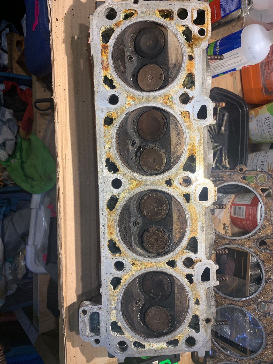
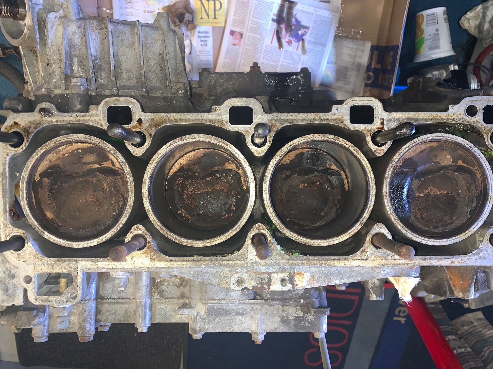
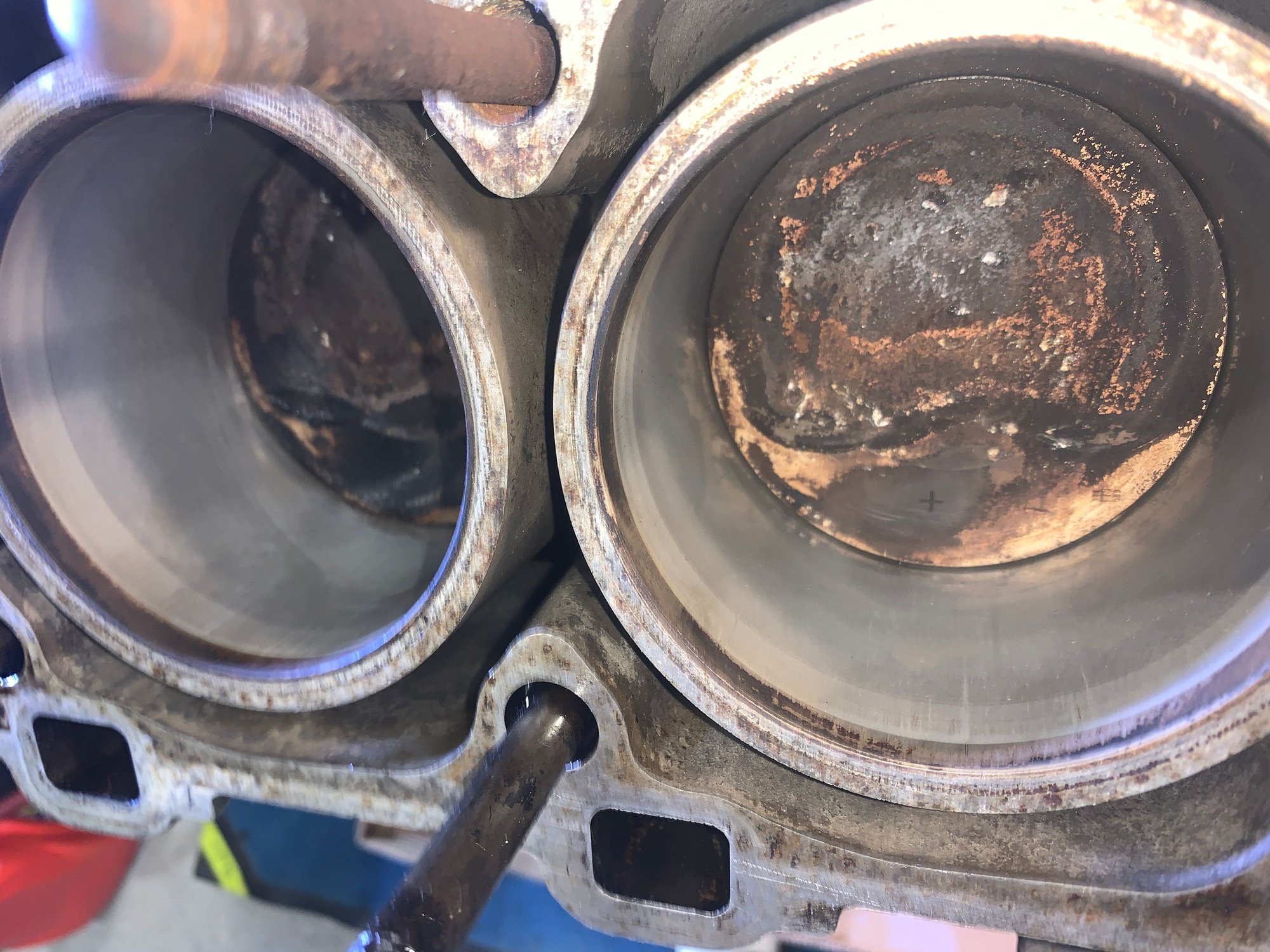
Next was head removal. It is pretty dirty, lots of carbon buildup but not terrible ( I think). To me the bores look pretty good. I was expecting a bunch of vertical gouges. They appear pretty smooth. The head has a lot of coolant residue which looks terrible. I vacuumed most of it out and stuck a thin brush into the passages to scrub them out. Its come pretty clean. I don't see any cracks. I'll be getting the valve out then giving the head a good bath in hot water.
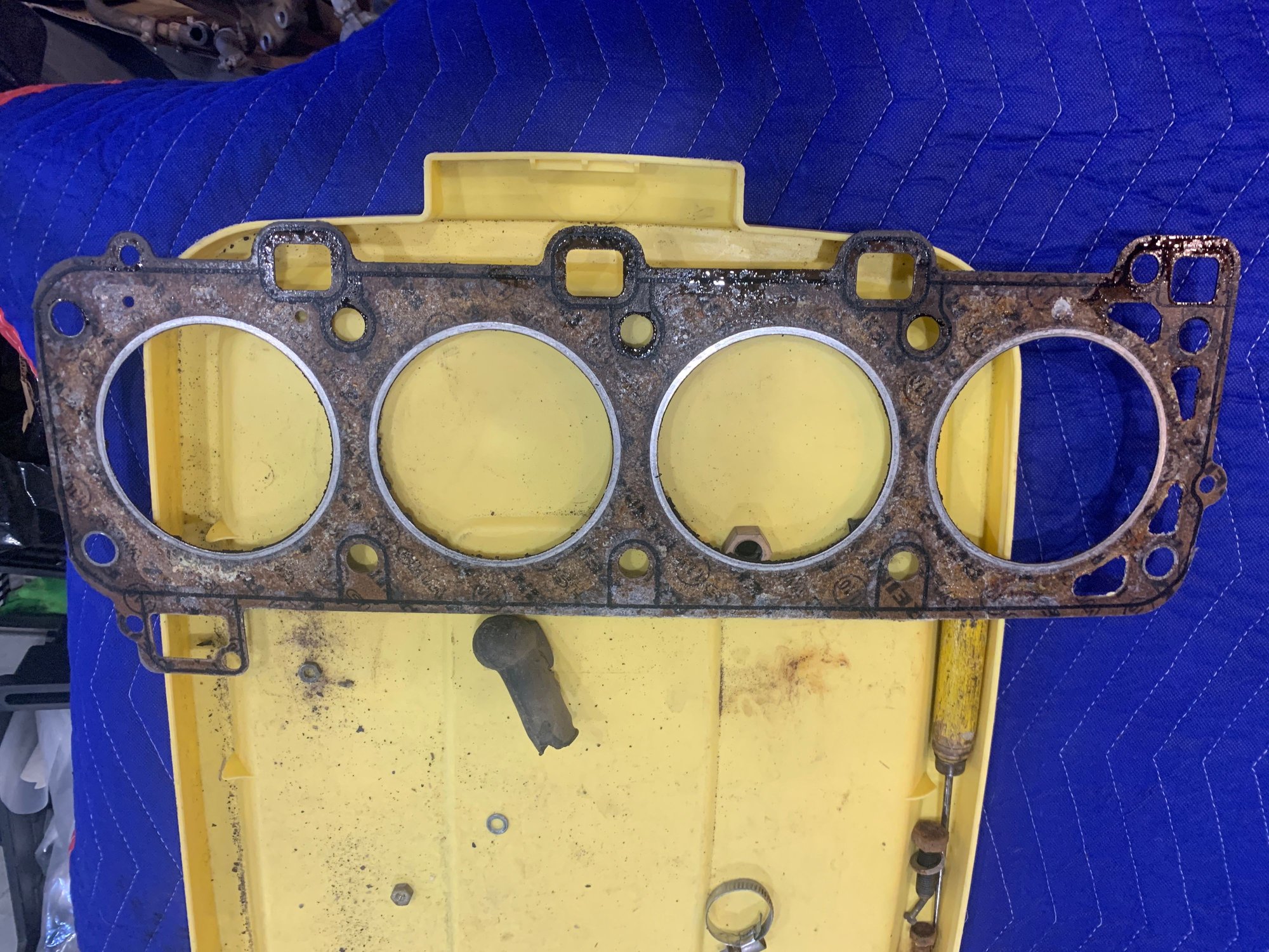
I notice on the head gasket it says 1.10 a few places. Is this a thicker than standard gasket? Maybe it doesn't mean anything
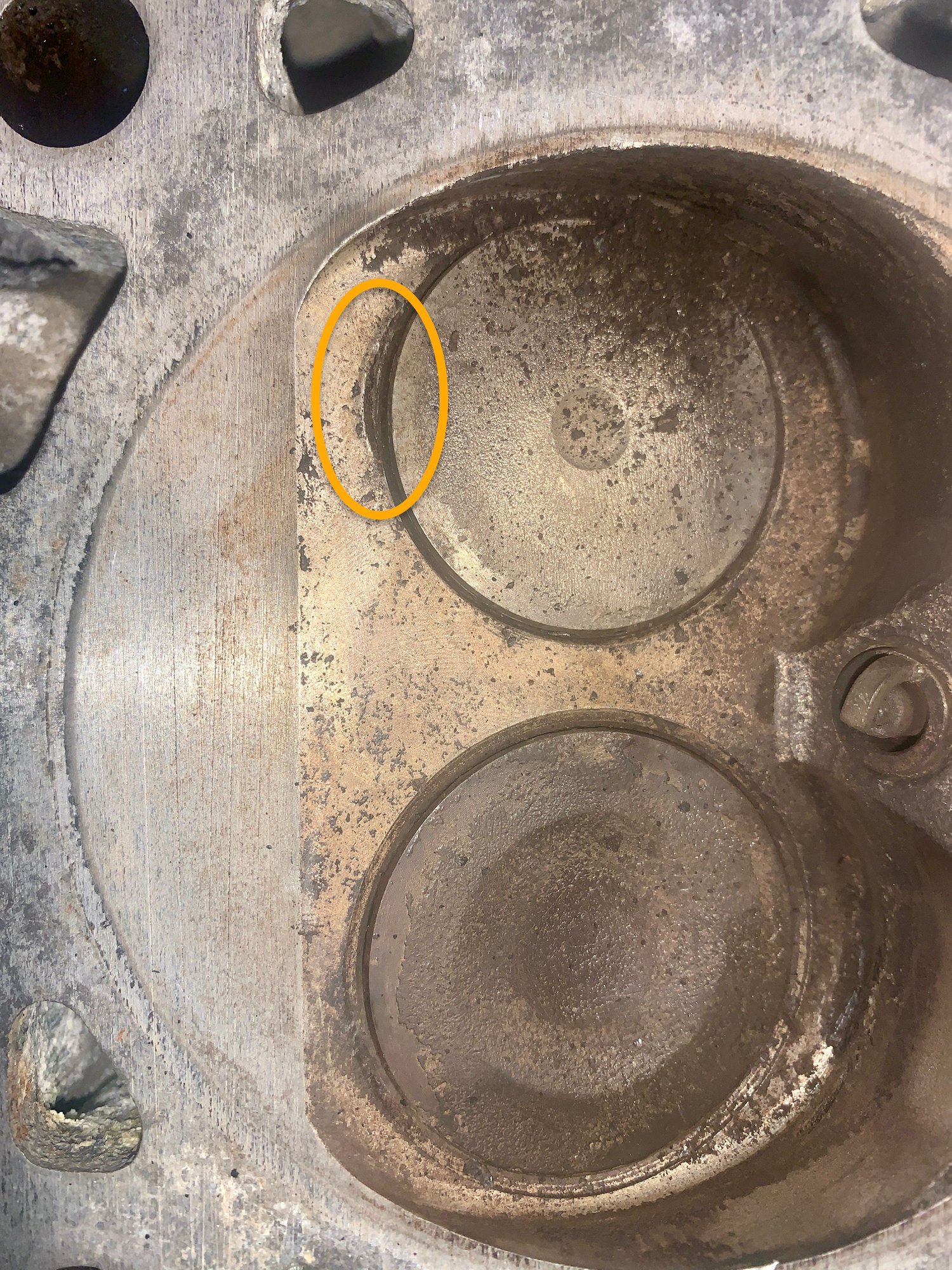
Also I notice 3 out of 4 cylinders have this little dent/divot beside the exhaust valve. Indications of a previous bent valve collision?
Lots more cleaning of the head and block to come. Then checking over everything Please comment if you see something or have any advise. I have done a HG before but not on a 944. Looking around at what I'm doing ,wondering WTF have I got myself into LOL.
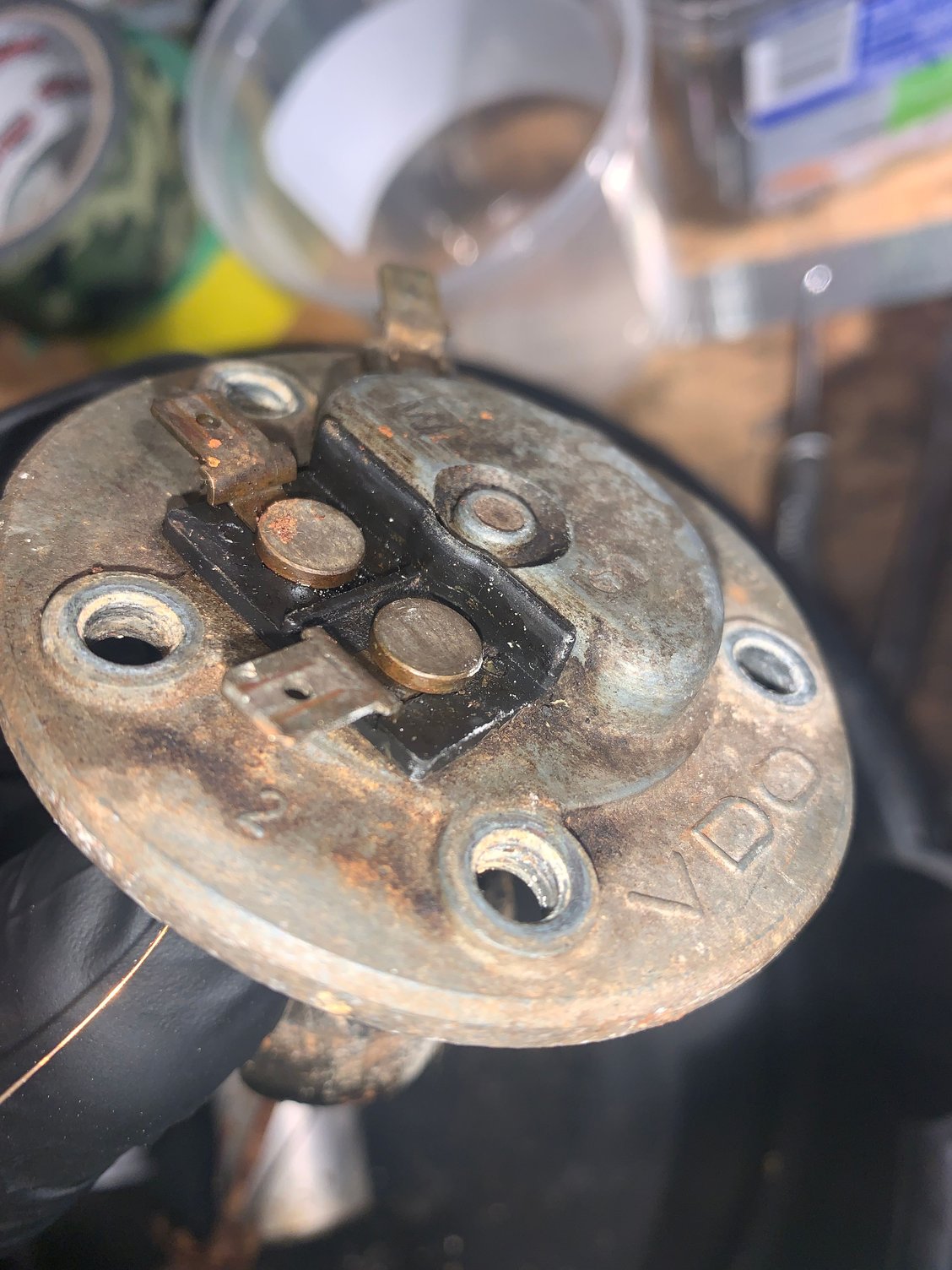
So after seeing what Gasngo is doing to his fuel sender got me wondering about mine. I know the tank is toast. So I pulled the sender. Pretty sure this is unusable
Hey let me ask a ? and I know it wont be easy with what you have buuutttt can you carefully look and determine whether the wishbone piece on terminal G actually sits against the underside of the lid to make a ground contact. I have cleaned mine and let them dry and still no continuity. I would like to know if you find any kind of small disk, piece of rubber or any kind of insulator between the lid and the wishbone contact. Im pretty confident it ought to ground thru the lid but Im being careful as I move forward.
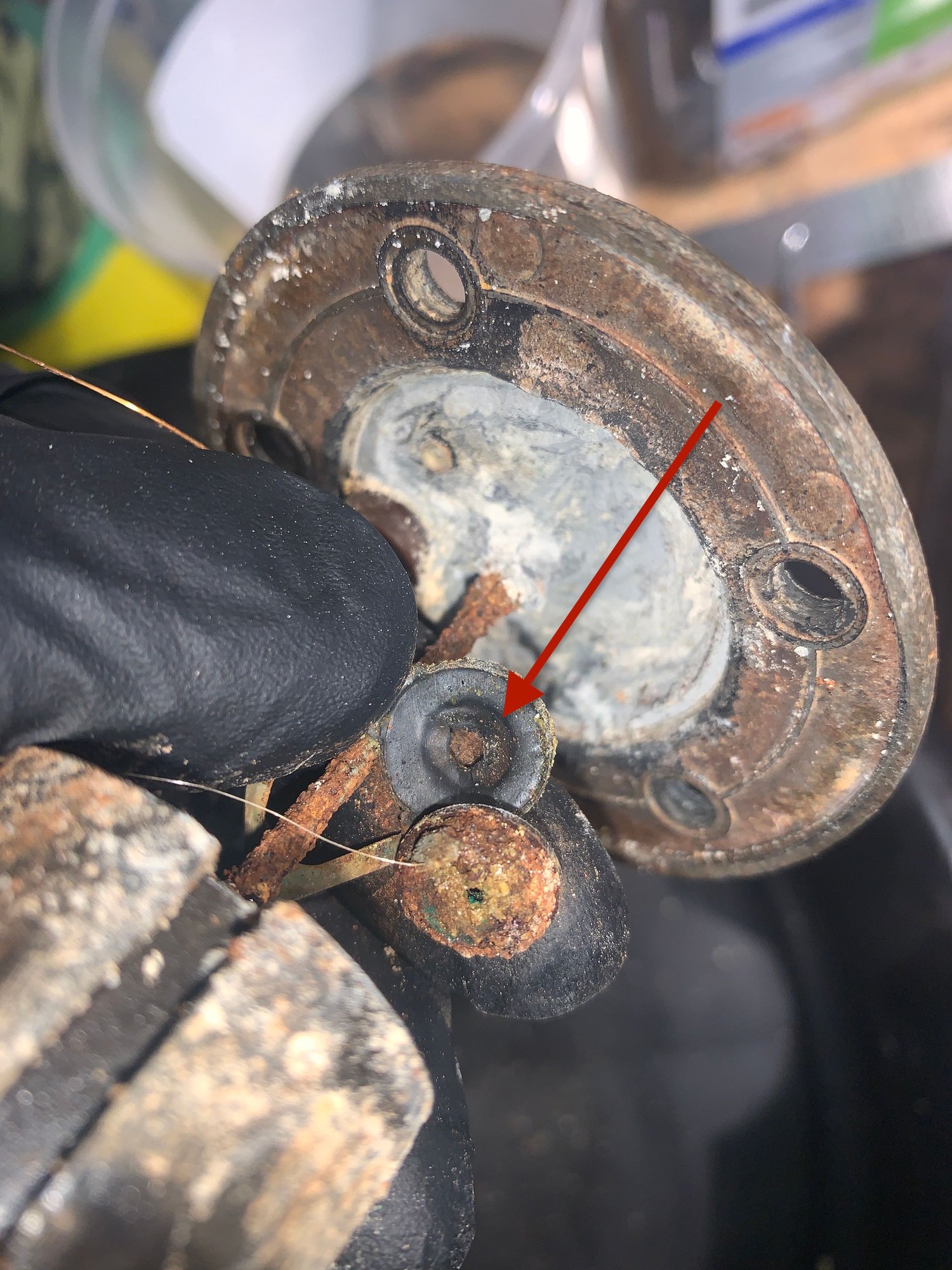
OK heres some pics of what Im seeing. Ive dropped some arrows to try to point out what I "think" I'm seeing of how this may work
This first pic shows the wishbone piece you refer to, on top of that is a rubber insulator, the rusty disc is the topside of the wire holder.
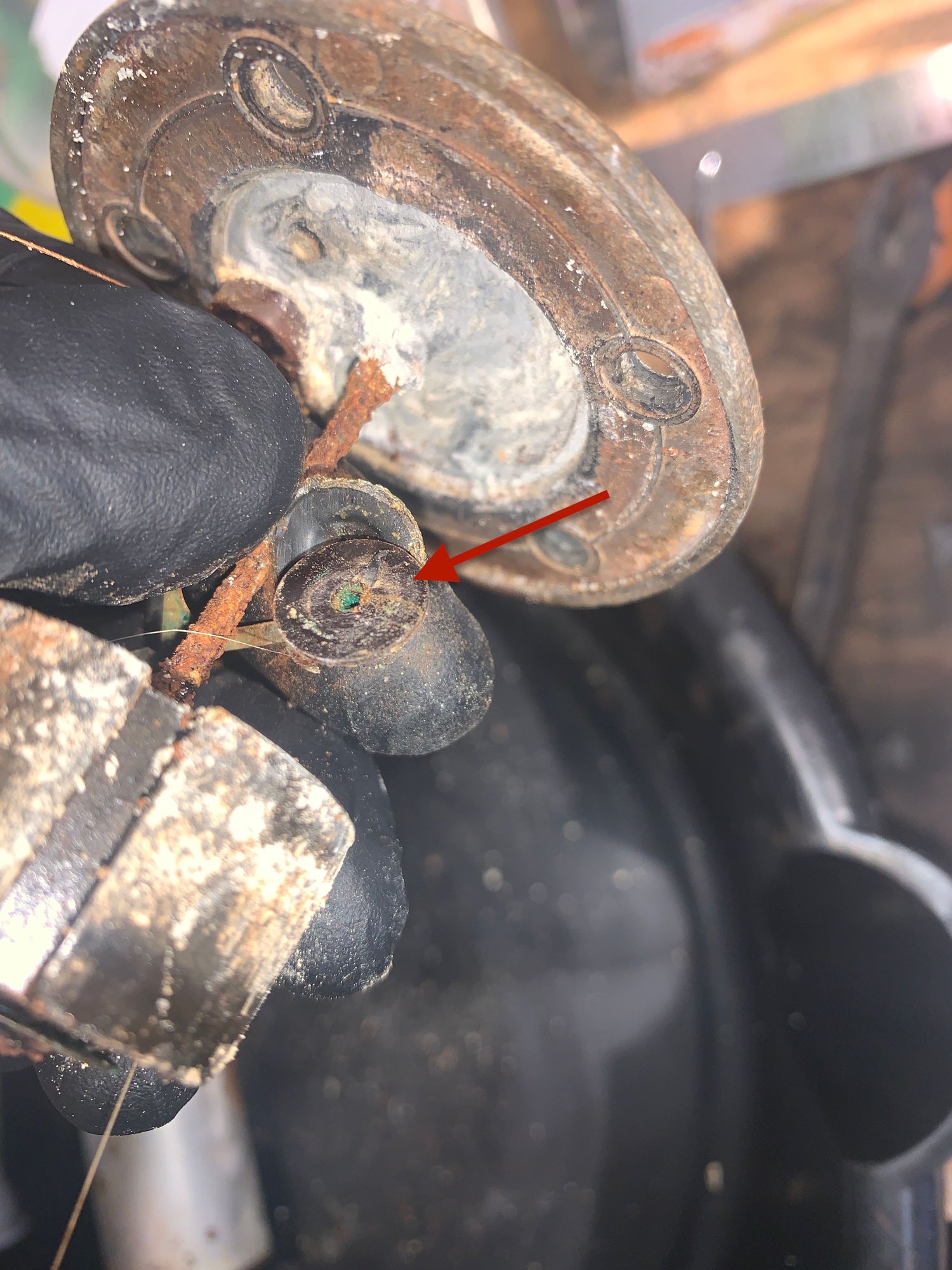
the rusty disc flipped over shows it has a bakelite like disc that was connected to a shaft that went up to the top of the sender
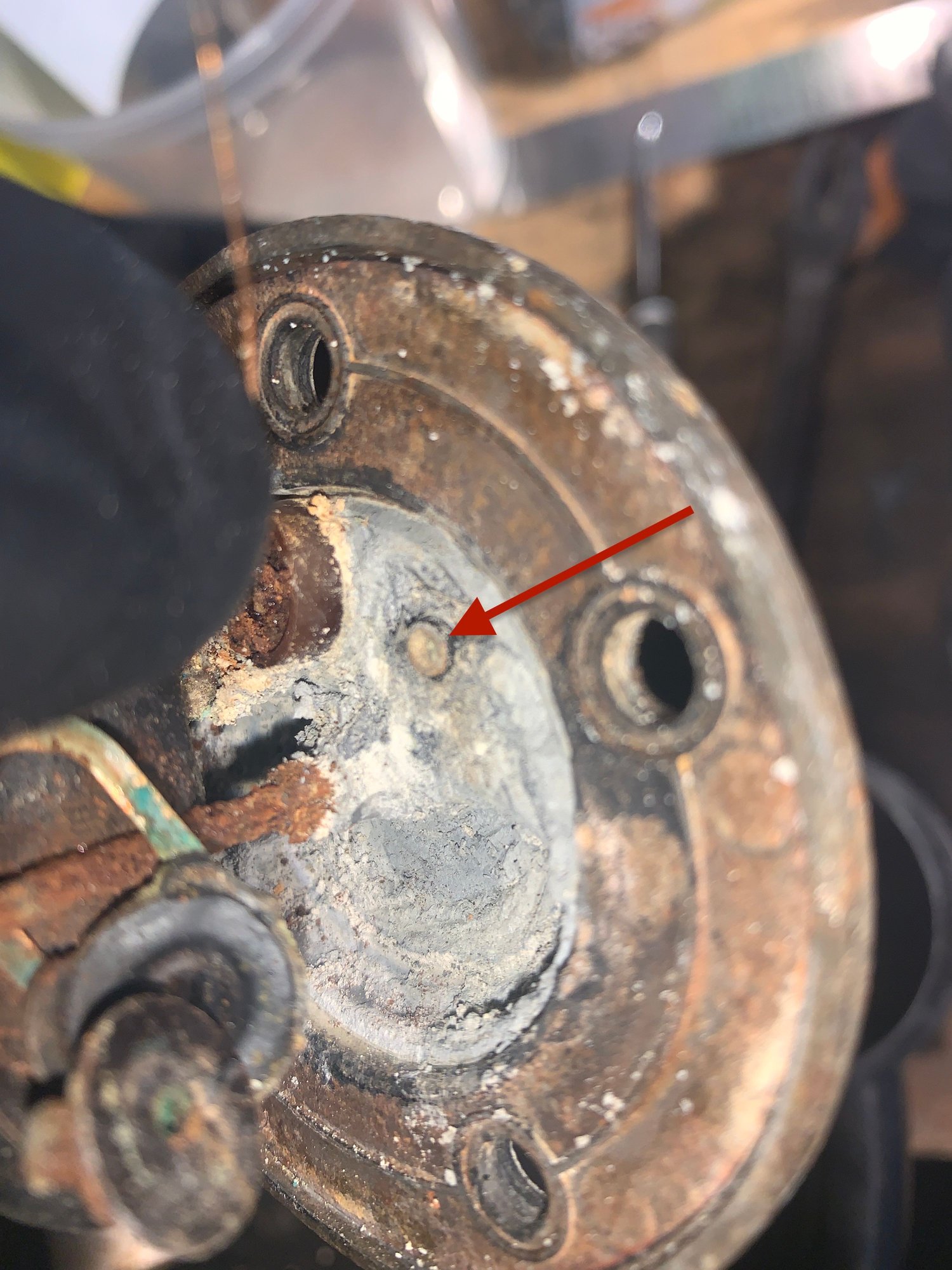
This pic shows whats left of the shaft that connects to the outside electrical connection , That shaft appears to be insulated from the metal of the sender top. I didn't get a pic , and there was very little left of what looked like more rubber or plastic attached to the underside of the top. It looked to me like it was the remains off more rubber insulation between the top of the wishbone piece and the bottom of the sender top.
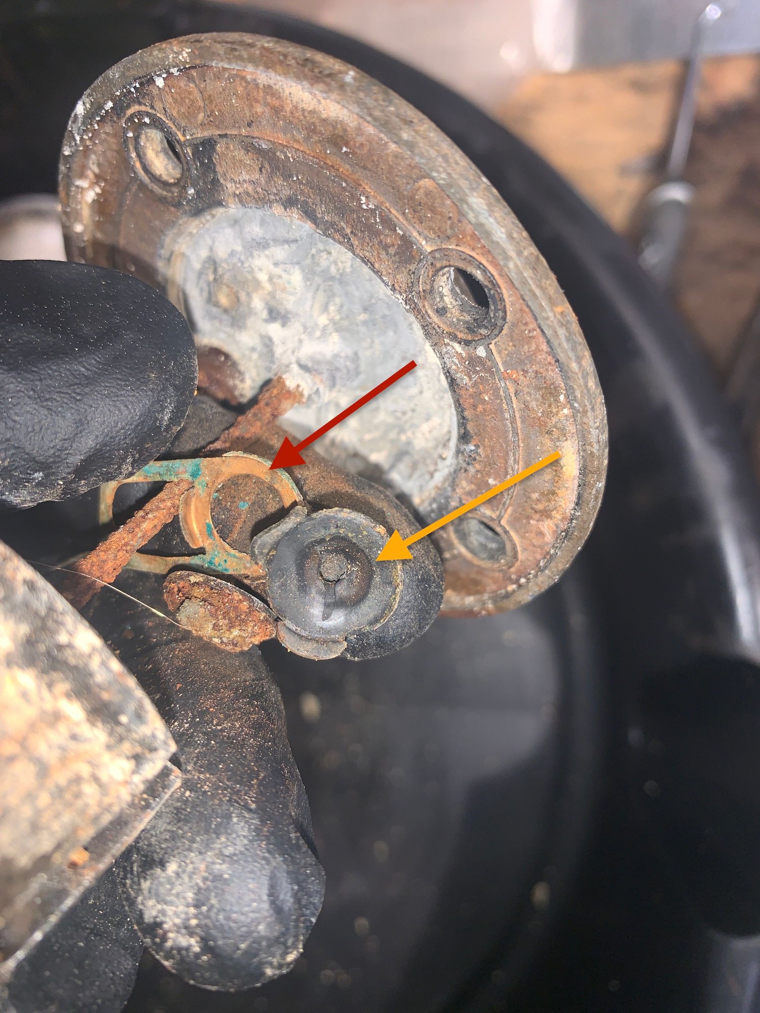
Just another pic showing the rubber removed from the wishbone . Not sure why I put arrows here. LOL.
Then at the top both of these connections seem to be insulated from the metal
So I hope this may help. I would say from looking at this , that signal is NOT suppose to be grounded on the sender top, rather insulated from it. Need more pics? or anything else checked? Happy to help as I'll need this info myself
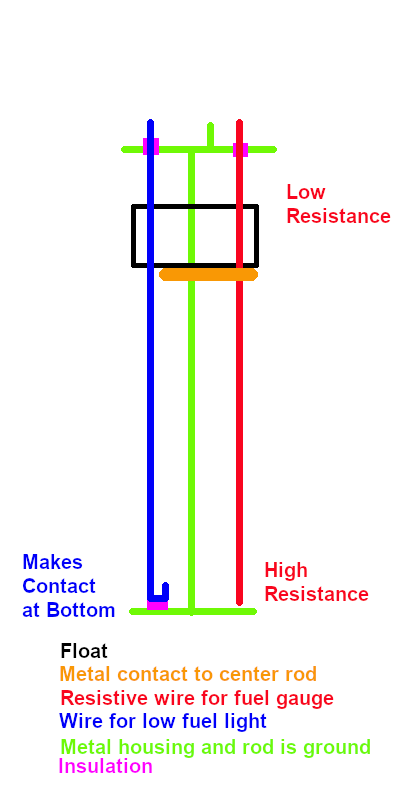
I'll start by saying I haven't had mine apart, but I do know how it is supposed to work. The two terminals at the top are insulated because they are the signals for the fuel gauge and the low fuel warning light. The low fuel light signal goes down one wire, and it is a normal wire, and makes contact through the float when it is at the bottom to the center post rod (which is grounded through the third connector at the top.) This wire will be insulated at the bottom connection. The gauge signal goes down a resistive wire and shorts across to the center post rod wherever the float is. The resistance therefore gets bigger the more resistive wire is in the circuit. This wire may or may not be grounded at the bottom (connected electrically to the plate at the bottom,) it does not really matter.
Good info. Lets not get deep into Buyits thread on his car resto. Im good if you guys want to repost all this on my thread regarding repair sender and keep in one place that would be ideal. Once its done if Buyit want to delete or remove this than Im fine or leave it if you want that ok to just get to the specific thread. Im sure there a answer in all of this. Ill make a comment over there now.

 01-29-2022 | 02:20 PM