blown engine

 09-08-2015, 10:57 PM
#362
Rennlist Member
09-08-2015, 11:25 PM
#363
Rennlist Member
Let me refresh your memory Charles. You were the first ones to purchase my bearing and both you and Jake gave your "professional" opinion on the 986 forum. This is how it all started. I did not just start attacking your company out of the blue, I don't care what you both do. I was defending my products and services which in Jakes opinion were crap.
http://986forum.com/forums/boxster-p...ines-sale.html
http://986forum.com/forums/general-d...g-failure.html

 09-09-2015, 12:45 AM
#366
Former Vendor
 09-09-2015, 01:40 AM
#368
Former Vendor
09-09-2015, 02:07 AM
#369
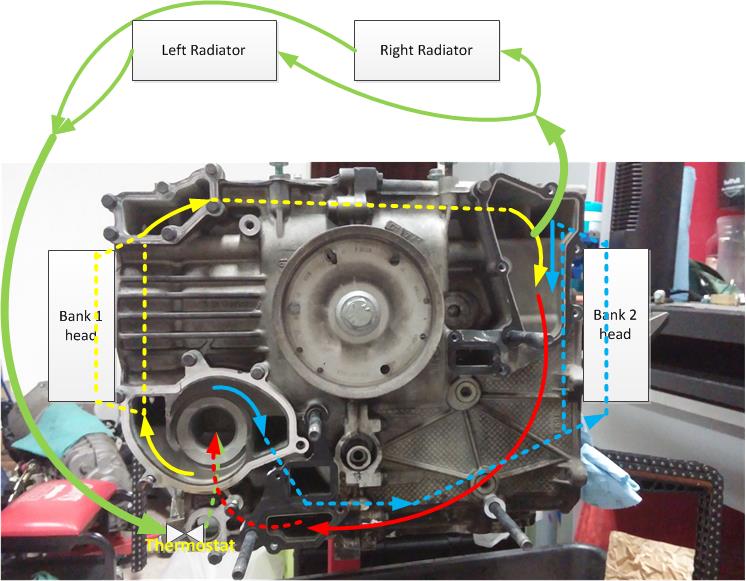
Since you guys changed topic, let me switch as well. I was able to trace all the internal coolant passages cast into the block. My question is "Is the green path of coolant flow correct?"
Dashed line means the line is internal hence not visible externally. The red path is provided by the oil pump assembly (removed and not shown in the pic). The water pump sucks up the coolant from the center circular port (red and green flow) and pumps out the yellow flow for bank 1 and the blue flow for bank 2. Cooling the cylinders and heads from the bottom up to the top of the engine. Then the (yellow and blue) flows merge at the upper right then into the red arrow which goes back to the pump.
The return side of the green flow is controlled by the thermostat so when the coolant is not up to temp, the green flow is not flowing but when the thermostat starts to open, the green flow will start to flow. The thermostat is sensing the temp of the red flow.
09-09-2015, 09:16 AM
#370
Former Vendor
Thats fairly close, BUT the front console enters the equation, and changes things up a bit.
You'll learn the coolant path in my classes. We go over this first, in the 101 class, online.
You'll learn the coolant path in my classes. We go over this first, in the 101 class, online.
09-09-2015, 02:48 PM
#371
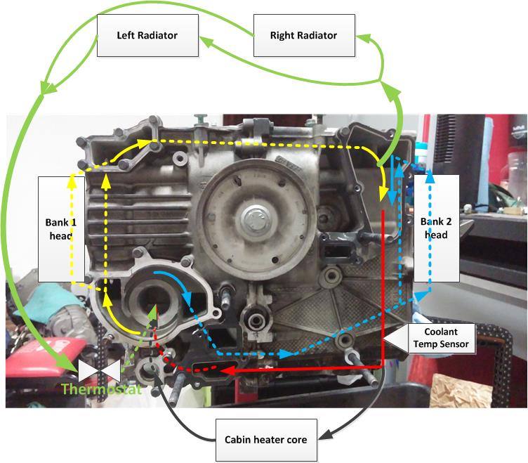
Jake, it's good to know I will learn this in your engine rebuild class. By "Front console", did you mean the heater core? That seems to be just another parallel circuit similar to the cylinder/head circuits? I've added that (black flow) and the coolant temp sensor, which taps into the lower part of the red flow in the diagram.
If the green flow (and its direction) is correct, that begs the question why people say the coolant temp sensor is at the RETURN path AFTER the radiators when it's actually at the return path of the coolant right after the cylinders and heads?
If the green flow (and its direction) is correct, that begs the question why people say the coolant temp sensor is at the RETURN path AFTER the radiators when it's actually at the return path of the coolant right after the cylinders and heads?
09-09-2015, 03:42 PM
#373
Got it. The front console is not shown in the pic and I tried to represent it by the red flow. I found it interesting that there are multiple parallel flows which are controlled (metered) by the cross section areas of the opening of each flow. ...must be very carefully designed as one flow affects the other as they are in parallel and coolant will try to find the path of the least resistance.
09-09-2015, 03:50 PM
#374
Former Vendor
Got it. The front console is not shown in the pic and I tried to represent it by the red flow. I found it interesting that there are multiple parallel flows which are controlled (metered) by the cross section areas of the opening of each flow. ...must be very carefully designed as one flow affects the other as they are in parallel and coolant will try to find the path of the least resistance.
Some aspects of the cooling system don't make sense.... Epoxy can change everything :-)
09-09-2015, 03:58 PM
#375
Yea, the front console is a big merger of a few flows.
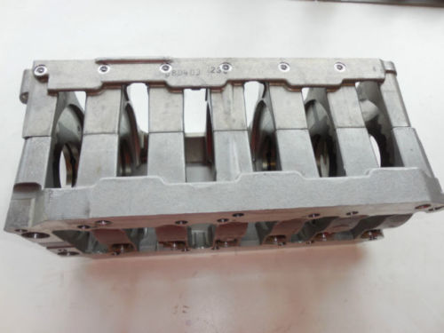
Another question. Do you know what are those 6 circular dots on the top of the craddle in the pic (of course you know. I should have asked if you could tell me...)? I can't find any documentation of those.
Pic is courtesy of autopartsboutique01 on eBay
Another question. Do you know what are those 6 circular dots on the top of the craddle in the pic (of course you know. I should have asked if you could tell me...)? I can't find any documentation of those.
Pic is courtesy of autopartsboutique01 on eBay