When you click on links to various merchants on this site and make a purchase, this can result in this site earning a commission. Affiliate programs and affiliations include, but are not limited to, the eBay Partner Network.
Making a Custom Gauge and connecting to CAN Channel for VBOX HD2
A couple people have asked, so here goes. This probably should have been a video...
Drawing the Graphics:
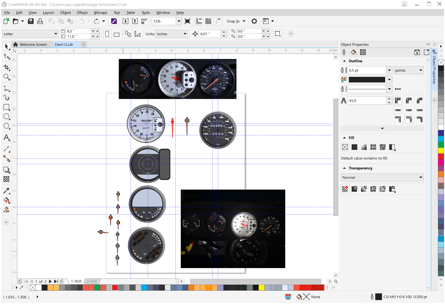
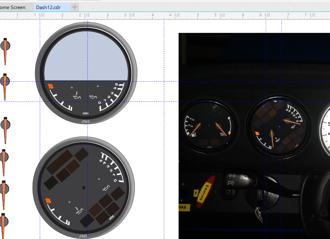
To Start with, I use a vector illustration program called CorelDraw. You can use a CAD package or adobe illustrator. If you're a photoshop wiz, you might be able to pull it off with photos of the dash, but it's really hard to get the perspective right, and remove the stray reflections.
I start with a photo, then I draw over top of it in vector format. I typically use the fonts available in Corel/Windows.
This is an example of gauges I made for a Texas RS's beastly RSR tribute.
I tend to go a bit nuts with this part.
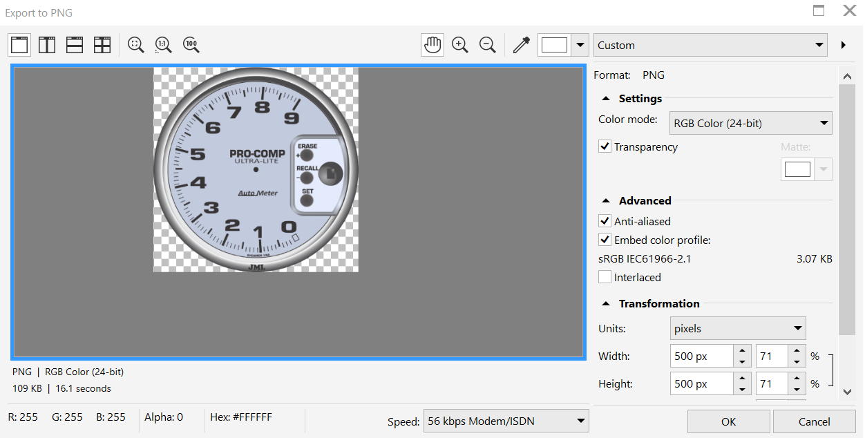
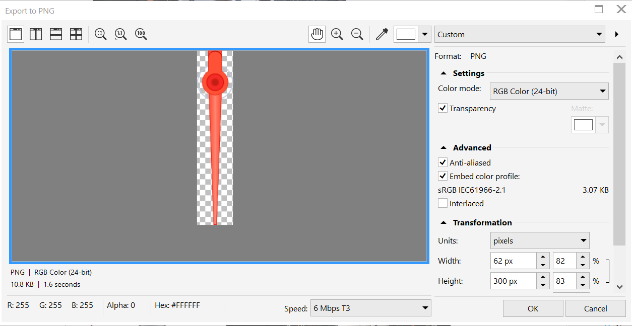
You will need to export your graphics one gauge element at a time. The gauge and the needle. Most graphics packages allow you to pick something called the "Alpha" channel, which is a color or mask (area) that is interpreted as transparent by the program displaying the image. It's very important to define this in your graphics, and in this example with coreldraw, by default it's automatically everything that is not an object.
Gauge: 500px
Needle: 250-300px
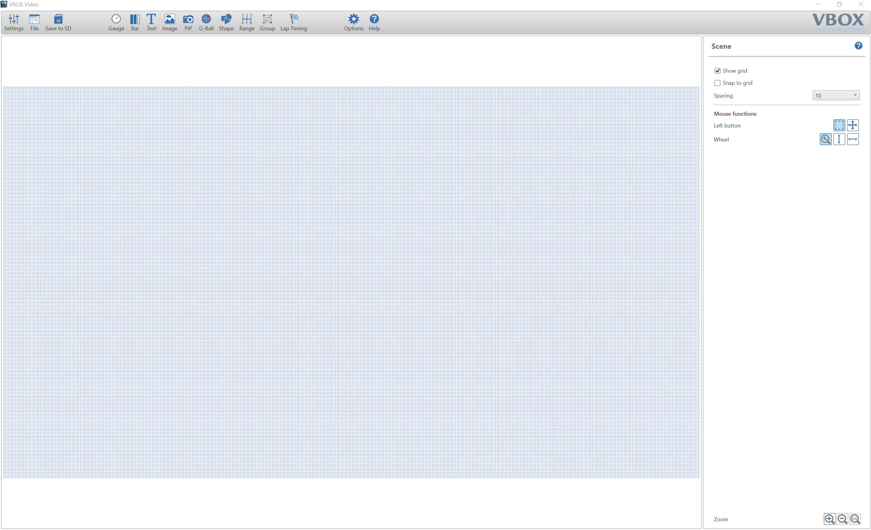
Building a VBox Scene
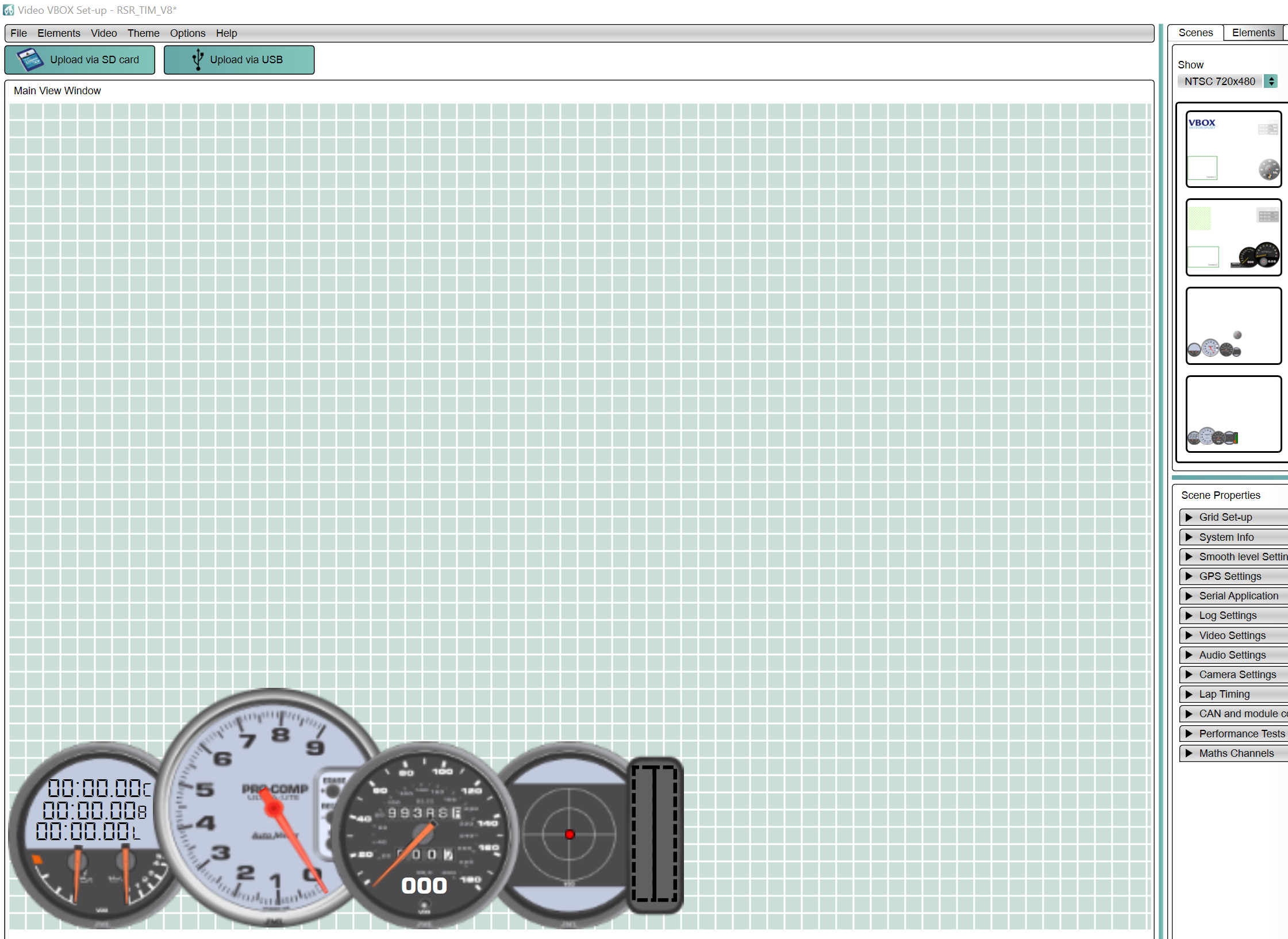
When you open the Vbox Video program, you'll see something like this - a blank scene.
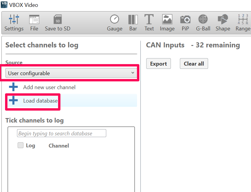
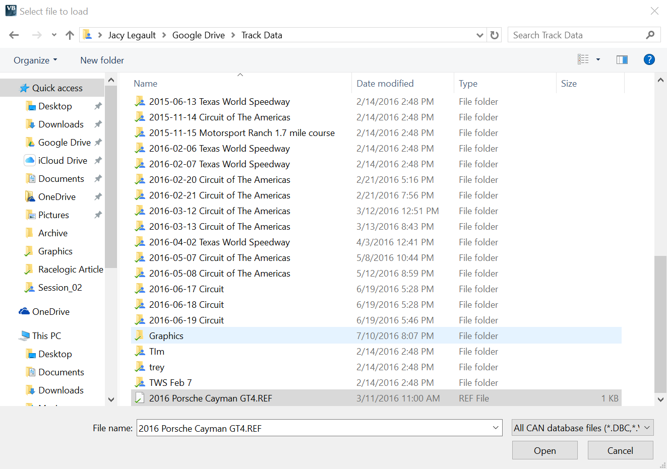
First thing, load your CAN database. In this example I'm using a GT4 database "ref" file. (Note - In reality, for this Scene, my friend needs to get his ECU mapped to a can config file, which he's not had a chance to get done yet. Custom car, custom engine, etc - sort of outside the normal box.)
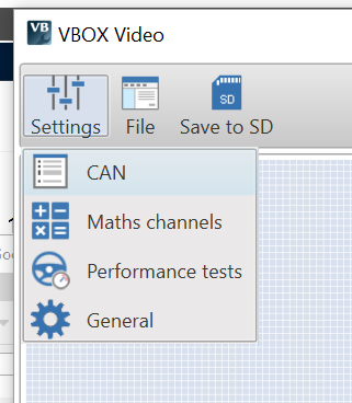
Got to the CAN screen:
Pick "Load Database"
Then find your "REF" file:
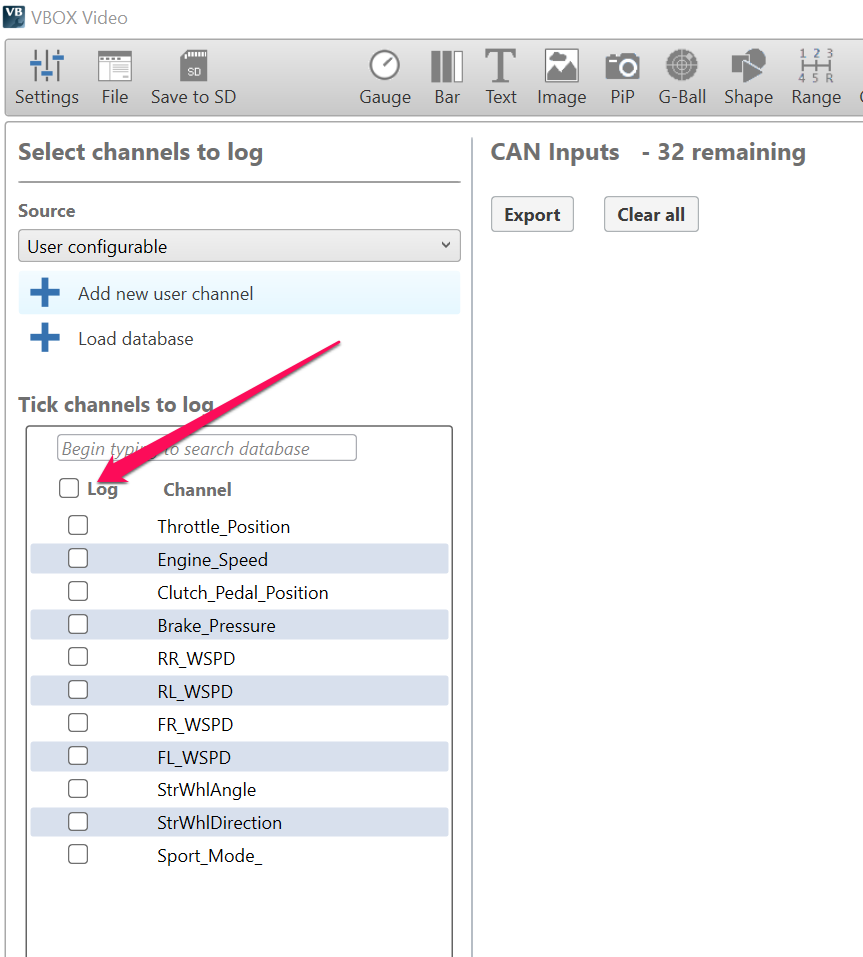
When you load it, a list of Can channels will present themselves. Make sure you select log all:
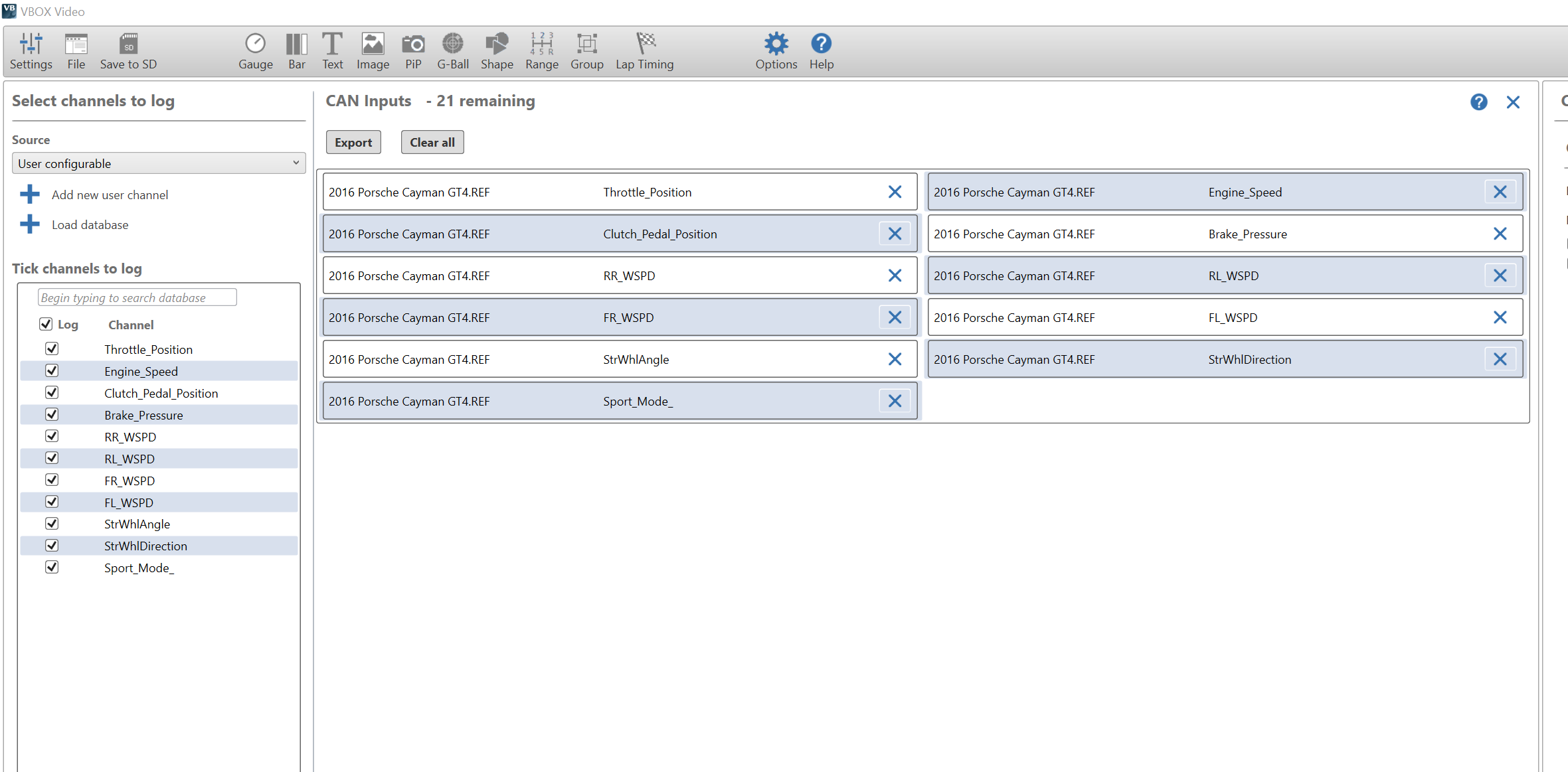
One you do that, you'll have a series of CAN channels to use in your scene:
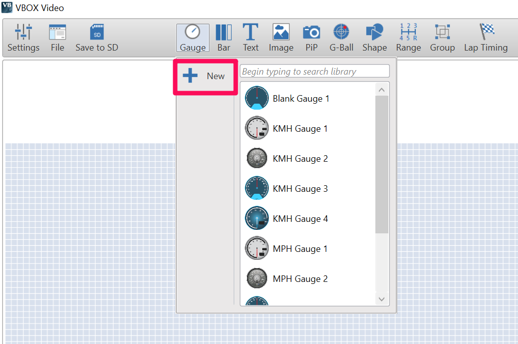
Go back to the scene editor (same menu as you used to get to CAN setup) and add a gauge. You could pick from many provide, but we'll add a new one.
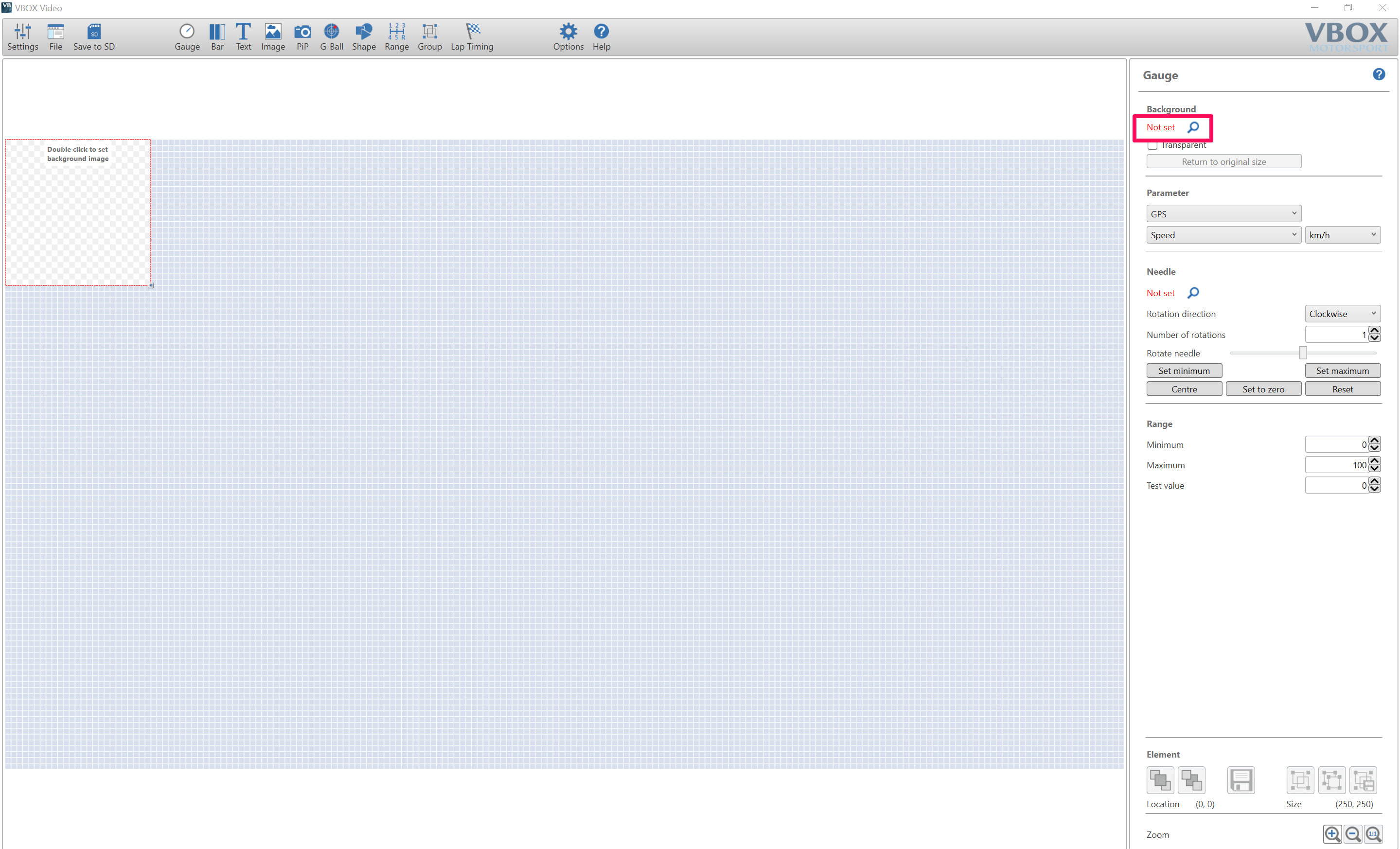
The default state of a new gauge is to have no graphics, no needle, and no configuration. To make a gauge you'll need a background image, a needle, a data channel to display, and a configuration for the needle that defines where it start and stops, and the scale of the data to display.
We're going to start by adding a background image.
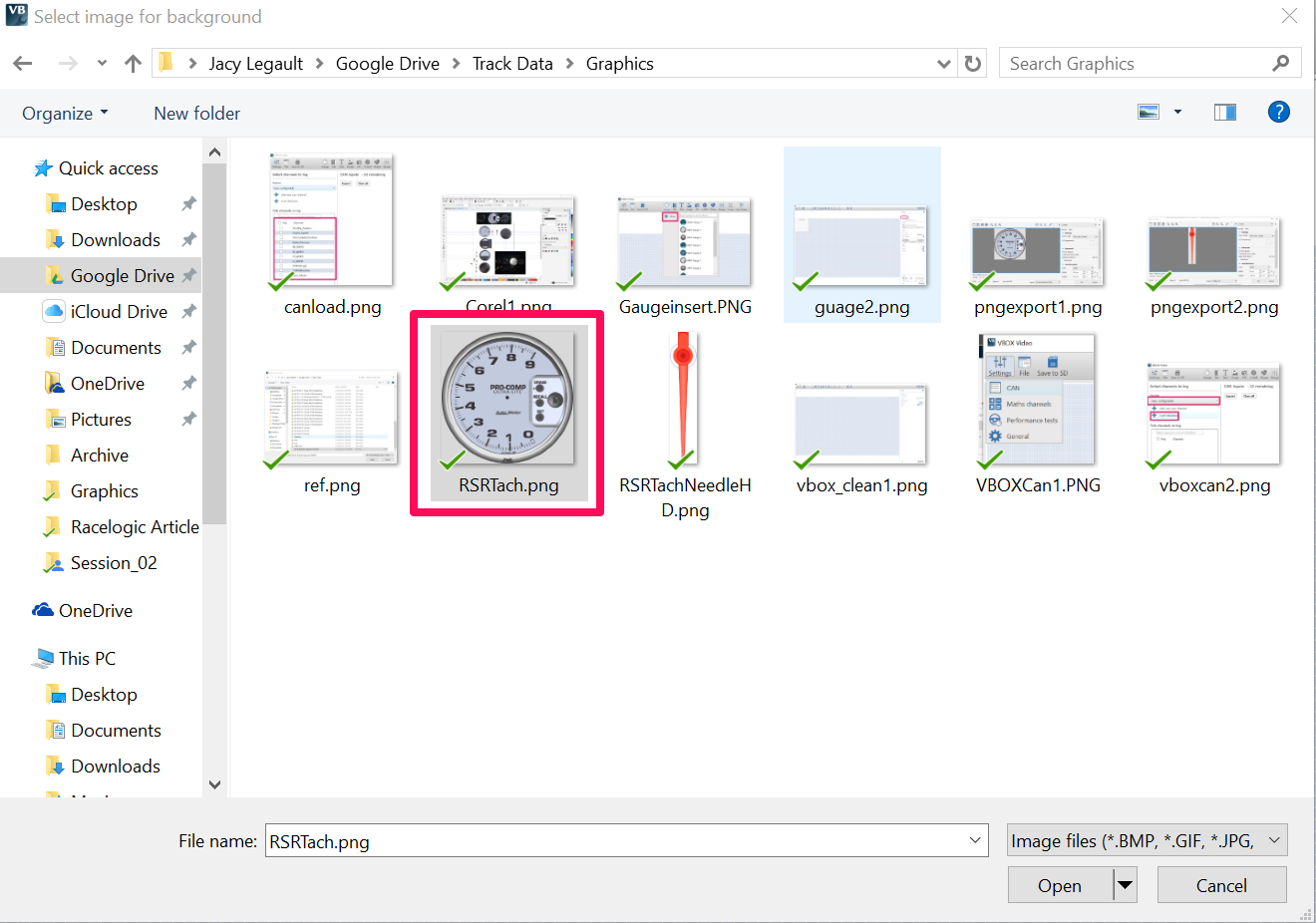
Pick the gauge image you exported earlier:
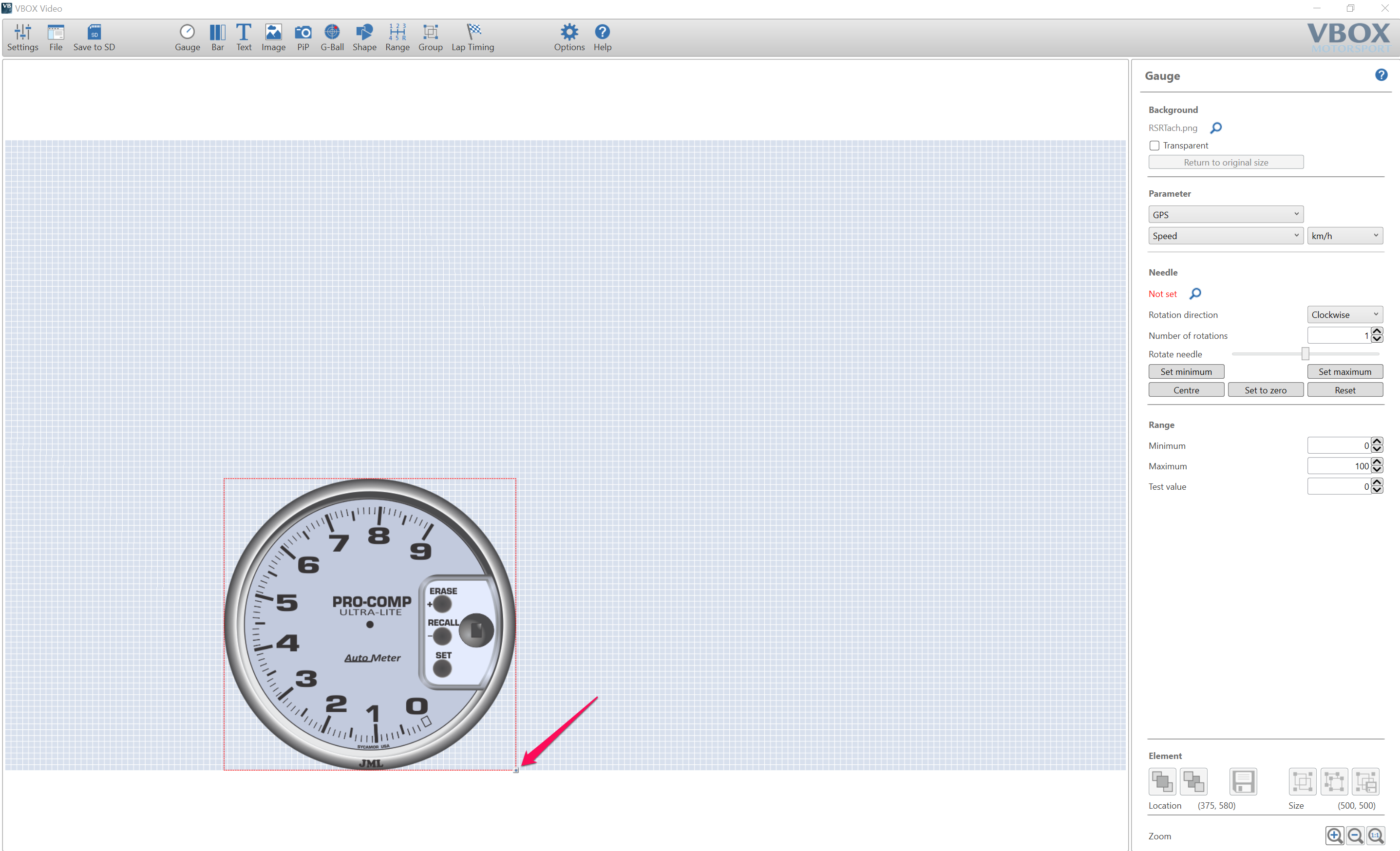
When you do this, you should see the image appear on the screen. You can move it to where you want, and you can scale it to the right size.
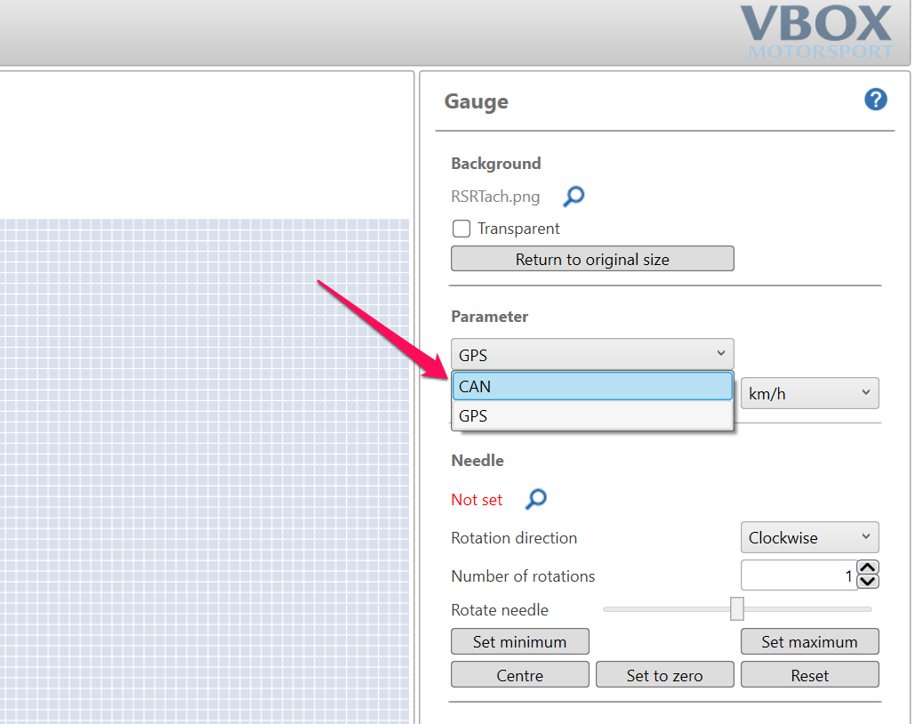
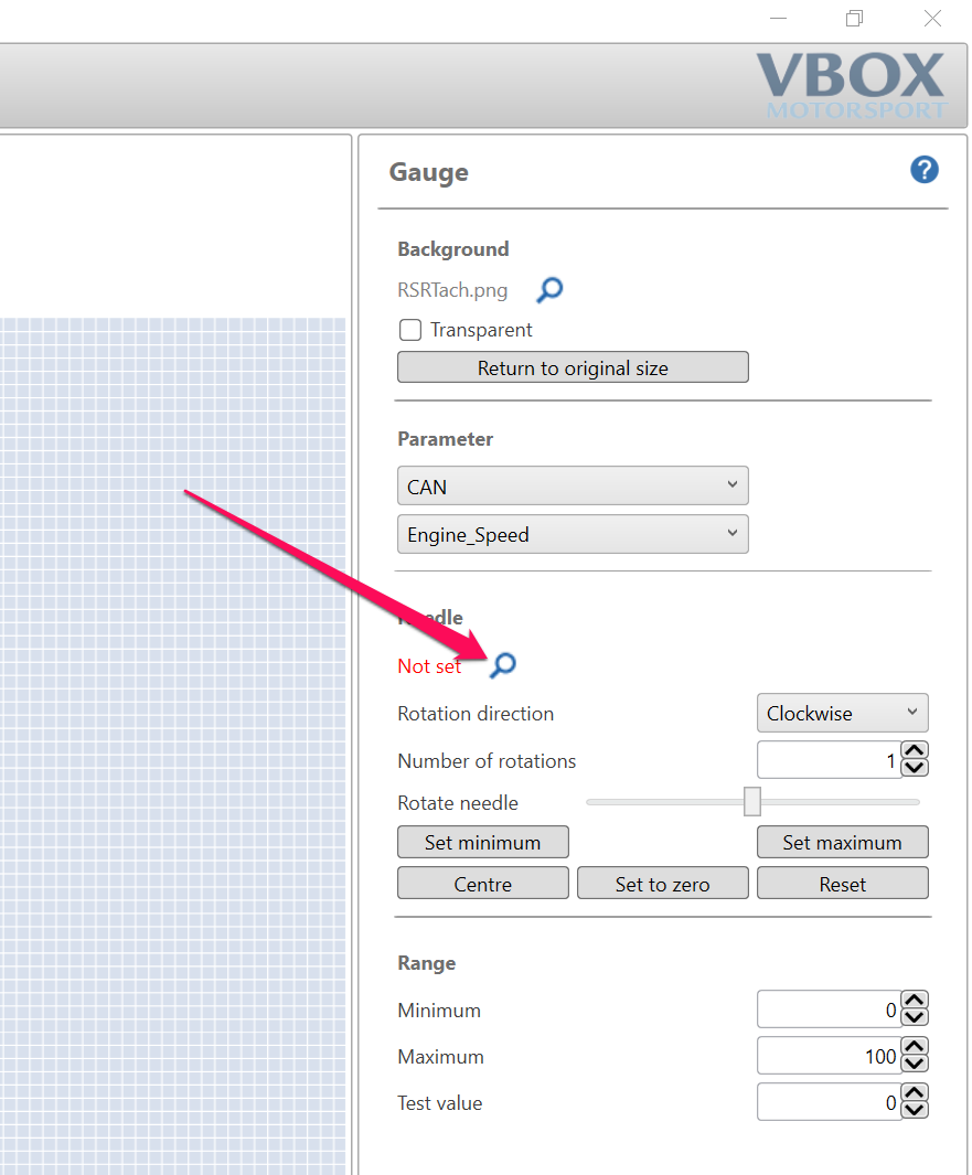
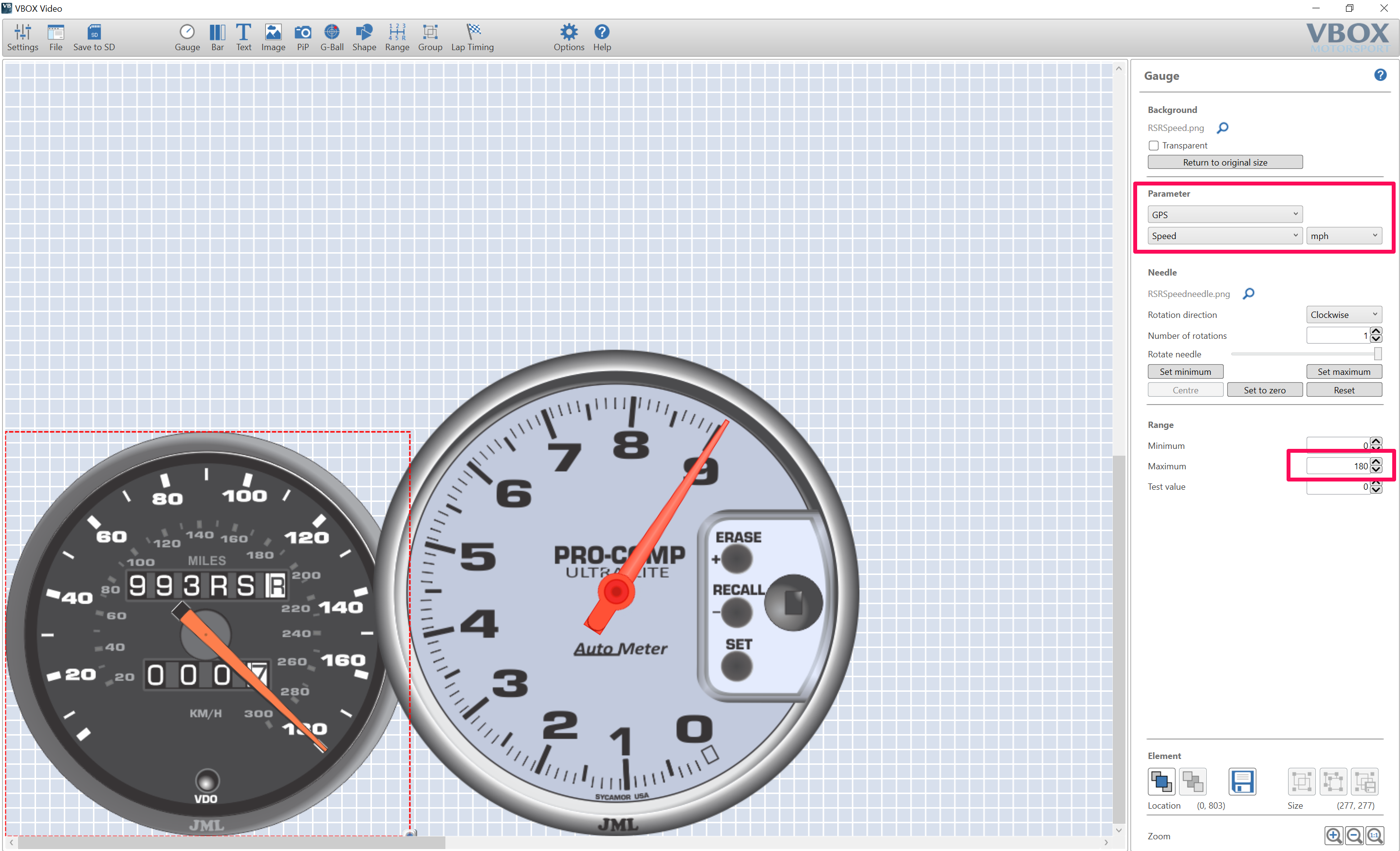
Next, assign the data channel to it. We're going to select a GT4 engine speed for this tach from the CAN channels you setup earlier in this scene.
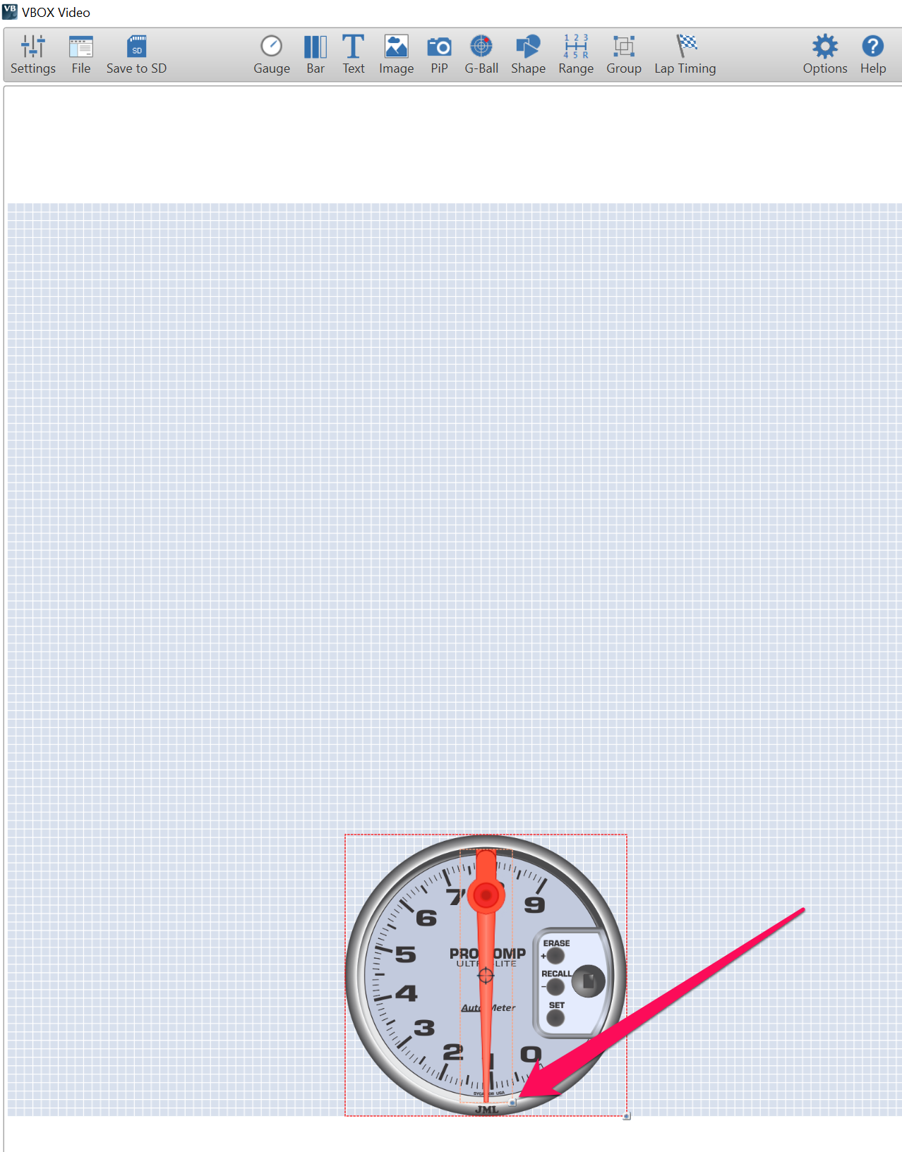
Next we need to add the needle image we exported earlier from our image editing software.
It's going to dump the needle in the middle of the gauge. It will need to be scaled and aligned to the center of the gauge.
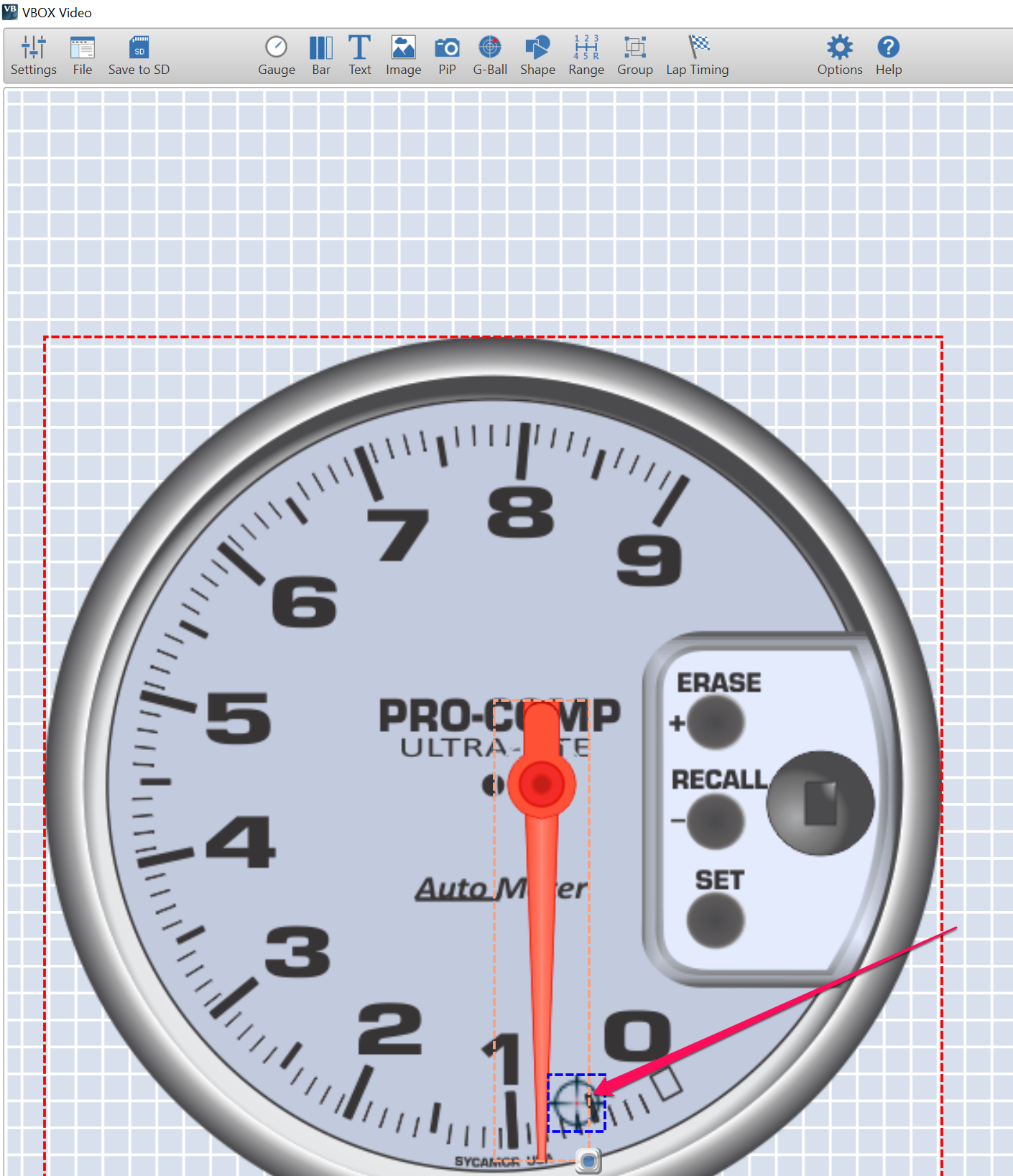
Scale the needle to the right size:
Move the rotational center of the needle to the right spot - there is a bulls-eye that you move to the rotation center.
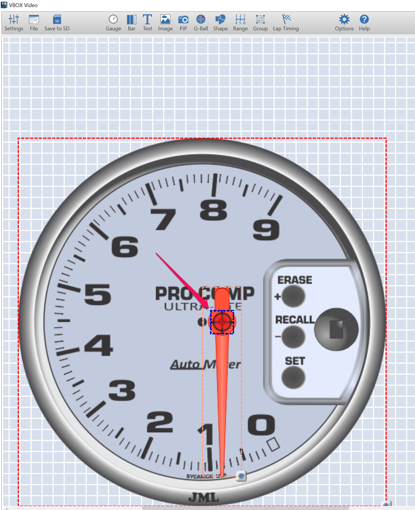
It should look something like this when you are done.
Move the needle to line up with the middle of the gauge. Using the cursor keys moves one px at a time.
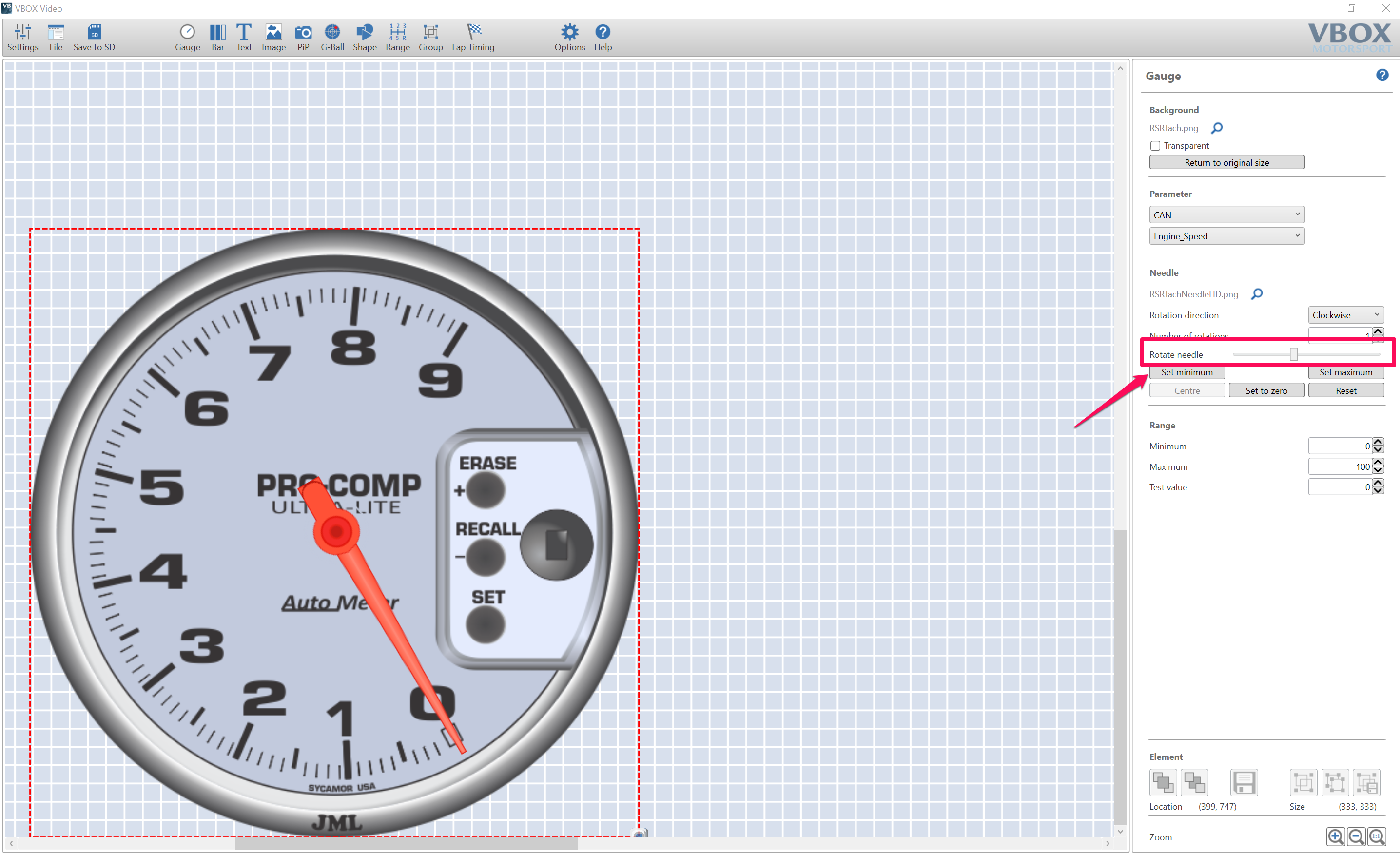
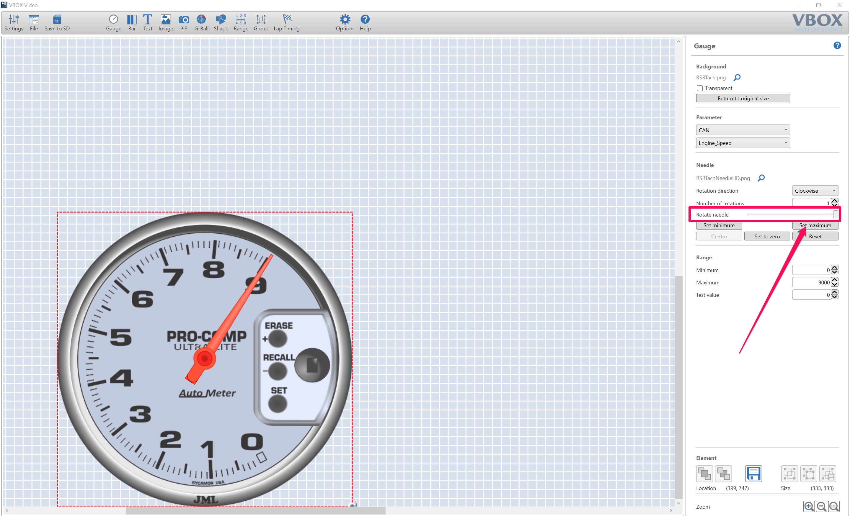
Now, using the config panel on the right side of the screen, you will align the needle with the start of the sweep. You move the slider until the needle touches the start and then press "set minimum".
And the end of the sweep:
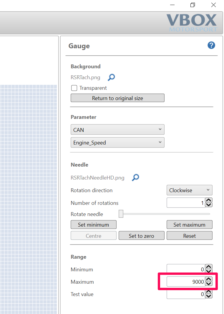
Final step is to enter the max scale of the data you'll see on this channel, corresponding to the max point of the needle sweep. In this case I'll make it 9000 to line up with the tach max I set for the needle sweep.
In this way, you can add other gauges. Here's the speedo, though in the wrong place (should be on the right).
I'm still working on his HD2 scene. Here is the SD version waiting for a Motec CAN database file.
Last edited by ShakeNBake; 09-10-2016 at 07:08 PM.
__________________ -Peter Krause www.peterkrause.net www.gofasternow.com
"Combining the Art and Science of Driving Fast!"
Specializing in Professional, Private Driver Performance Evaluation and Optimization
Consultation Available Remotely and at VIRginia International Raceway
A couple people have asked, so here goes. This probably should have been a video...
I tend to go a bit nuts with this part.
Hahahaha!. True dat...
The configurability of the background of the video for this system is only limited by your imagination. Again, 90% of users will do fine with the default scenes and icons, as well as use them as a standalone device, but IF you want to do something different...
These systems also accept analog sensor inputs for older cars, but the CAN assignments for the more modern cars that are available make things a lot easier.
This editing capability and editing system for fully customizable graphics for Video VBOX products is not new.
While the Setup program has been enhanced with the introduction of the HD2, SNB has been doing this for MANY years in the standard definition VBOX Setup program.
This scene creation can be done for ANY Video VBOX Lite, Video VBOX Pro and, of course, the new VBOX Video HD2 (notice the nomenclature change in the name of the unit, it's how the manufacturer and the dealers keep it straight!).
It cannot be done real-time on the Video VBOX HD, a single camera version introduced in 2013, but it can be added in post processing.
It's a very good, very powerful system and really pioneered the synced video/data and comparison software in a usable form. Unlike a competing system, it does render data onto the video real-time, so you COULD (and many people do) just pull the chip and play the fully instrumented video. Best of both worlds.
One thing that's not explicitly mentioned above but that matters for getting things like needles to look "right" is transparency.
VBOX Video as an app for creating scenes will look at the alpha channel for transparency information if the image has it. For needles, you want the outline of the needle to show but the "background" that it's drawn on in the image file (they inevitably, so far as I can tell, contain rectangular shaped images) has to be transparent...by painting the background around the outline of the needle itself with transparency information instead of visible color you can get rid of it.
There's a vague reference to transparency in the documentation where it talks about the backgrounds for elements but the user manual doesn't really say anything about transparency for the foreground (needle for example) pieces of the element.
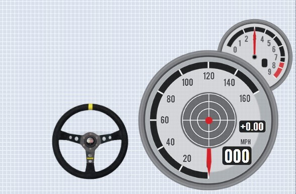
Since there's a picture of a steering wheel "needle" in the user manual and I'm not so fond of the bar style of indicator for the steering angle, I thought I'd try and make a wheel using a gauge element. Getting an image of a wheel and making the areas transparent between the rim and spokes and outside the perimeter of the rim turned out to be the key to making this look right.
All image editors are a bit different but what I did was use the GIMP (this is a great free software tool) and set the wheel image on a white background. Then I used the "color to alpha" option on the "transparency" sub-menu of the "layers" menu to turn all white into transparent...save the result as a PNG (using that format preserves the alpha information, JPG doesn't). VBOX Video will honor the alpha information in PNG files.
Then to make a steering wheel I made a new gauge, added no background image, instead selecting "transparent" and then selected the resulting PNG image file as a needle.
The end result looks like this (set beside some other gauges for comparison).
I modified the math channel that I made over here to cap the steering values at plus and minus 360 degrees (typical value clamping code idiom: "Max(lower_limit_value, Min(upper_limit_value, x))" the formula referenced at that link goes in place of "x"). 360 is probably enough for track use but in point of fact the raw data shows the GT4 spits out +/- 470 degrees give or take. Using 360 though makes for two full revolutions that keeps the gauge setup nice and easy for the setting the max/min travel.
One corollary question: is there any shared repository of images for needles and gauges and the like for making elements or are we all stuck hand drawing things from scratch if we want anything that's not in the library already?? Come to think of it, I couldn't even find image files for the elements that are in the library -- did I miss those somewhere in my installed VBOX Video files??
Oh and I thought of one more -- is there a way to add a new gauge, such as the wheel one I made above into the local library?? I didn't see an easy way to do that but it might be handy compared to having to copy scene files to make variants that include elements you added that aren't in the library. [I guess there's a bit of a theme here in that I couldn't figure out how to save math channels separate from the scene file either yet so perhaps that's just a VBOX Video thing -- keep a master scene file that you progressively add elements you want to share across scenes and then clone that each time you make a new one.]
A gauge style wheel position indicator is the best way IMO! FYI - What I found in VBOX is that it does not like -180 to 180 as an input into the gauge for some reason, so I needed to normalize it to 0-360 to make it work.
Thanks for the point about alpha channels, I added mention of it in the example above.
Happy to contribute something since I probably managed setting up the wheel a good deal faster because I followed your tutorial, thank you!
Interesting comment about the +/- values -- the only trouble I ran into was scaling when I set the endpoints of travel instead of clamping the input values from the math channel. Other than that, the range didn't seem to cause a problem. In fact just for curiosity's sake I went back this evening and set the wheel to 3 full rotations and the range to +/-540 clamping the steering angle channel to +/-470 and it seemed to work like that just fine too.
When you say "does not like...", how did that manifest??
The only thing that looks very slightly wonky to me is it seems like the needle rotation as shown on the video overlay seems to lag by a sample. What I mean is, if the steering angle is held steady the position of the wheel looks correct but if I advance the recording sample-by-sample (ALT arrows) it looks like the wheel position lags getting to the correct steady state position by one-ish sample positions. Not really too much of worry because it's not super distracting when the video runs, but if I were zeroing in on a very particular spot in the recorded data I'd want to cross check steering input between the wheel on the video overlay compared to the strip chart value of the math channel.
if I were zeroing in on a very particular spot in the recorded data I'd want to cross check steering input between the wheel on the video overlay compared to the strip chart value of the math channel.
That is why, on any detailed comparison, I always have the values window open on the lower left portion of the screen. No matter how much rendering you have, there will still be latency between the actual value measures and the elements rendered on screen. True with the SmartyCam, as well, to a greater extent.
Most importantly, the steering wheel element allows me to see the rate of change and also the degree of addition or correction after initial steering input. Yes, you can see it on the strip chart, but it's easier to process and takes far less time to quantify visually on playback.
There are things one could do to reduce the latency effect in a recording scenario like this but it might be computationally expensive (CPU and/or memory) enough to be prohibitive and like I said, I don't think this is really an issue when the video plays back at normal speeds.
I shouldn't be surprised at the latency, you're right...I guess I never looked at it hard with the AiM SoloDL/SmartyCam overlays because I wasn't doing much in the way of scene element calibrations...trying to figure out if I set up the wheel to properly reflect the math channel signal values made me look sample-by-sample and that's really the torture test for latency in this case

 07-11-2016, 01:03 AM