When you click on links to various merchants on this site and make a purchase, this can result in this site earning a commission. Affiliate programs and affiliations include, but are not limited to, the eBay Partner Network.
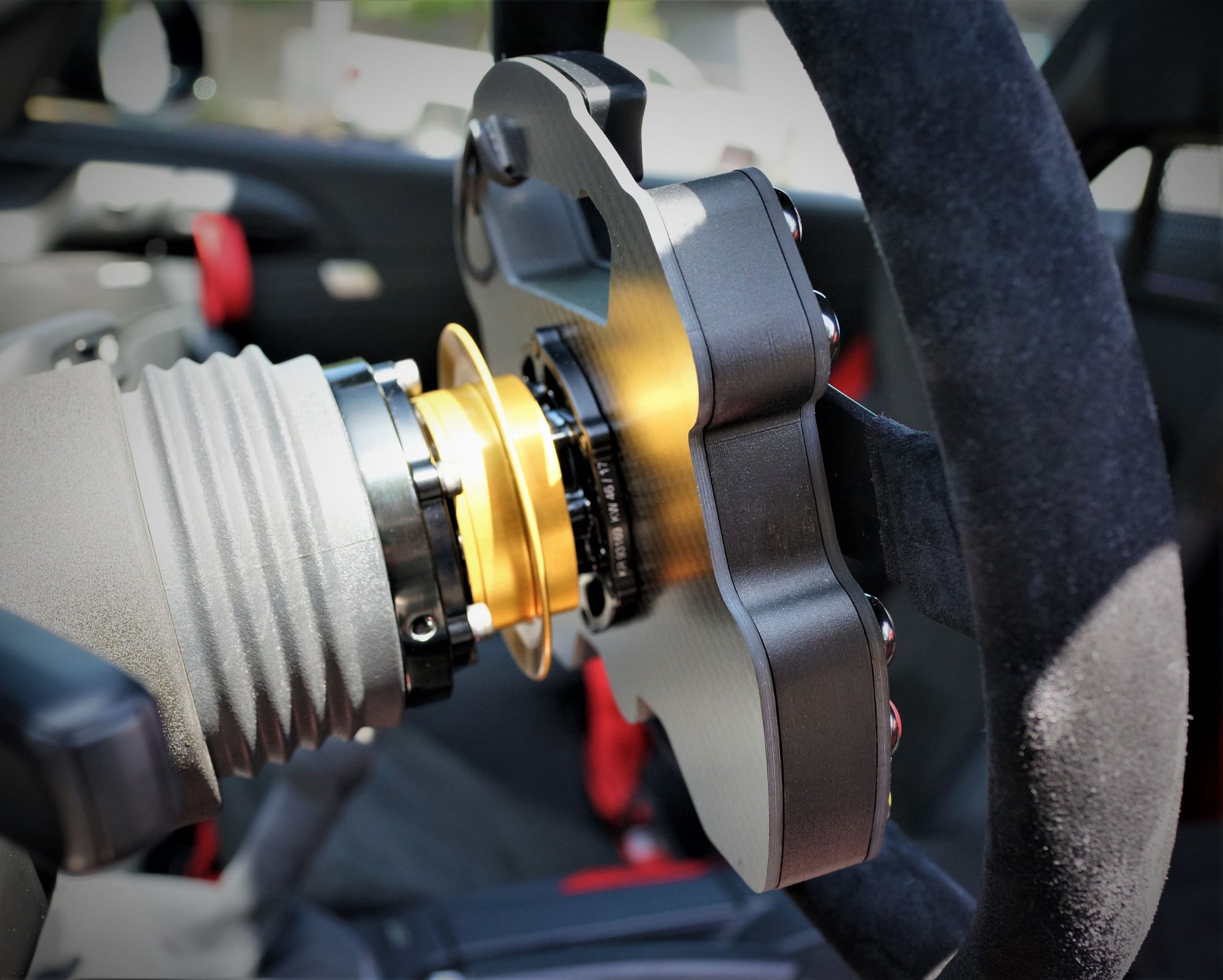
The RPM wire was run behind the lower dash, zip tied to another harness back there, routed forward to the lower steering column cover and finally through the modified clockspring seen in some of my previous posts.
There it connects to the 22 pin Krontec QR awaiting a steering wheel fit to carry the signal to something useful.
Here are some of the steps I took to get that signal to the shift light.
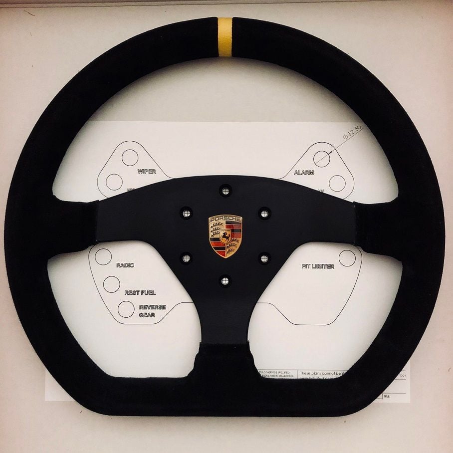
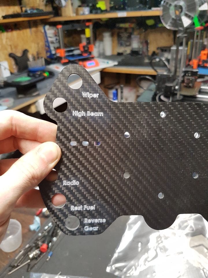
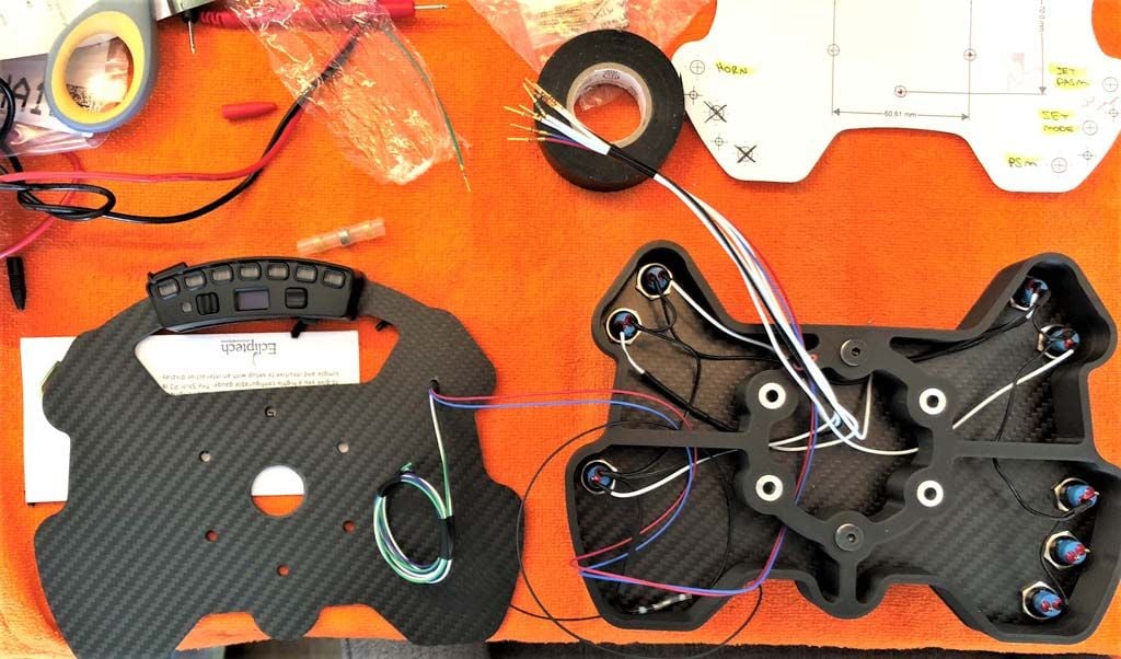
Firstly, I had a cover plate, enclosure and back plate designed and fabricated.
Here are a few mocks:
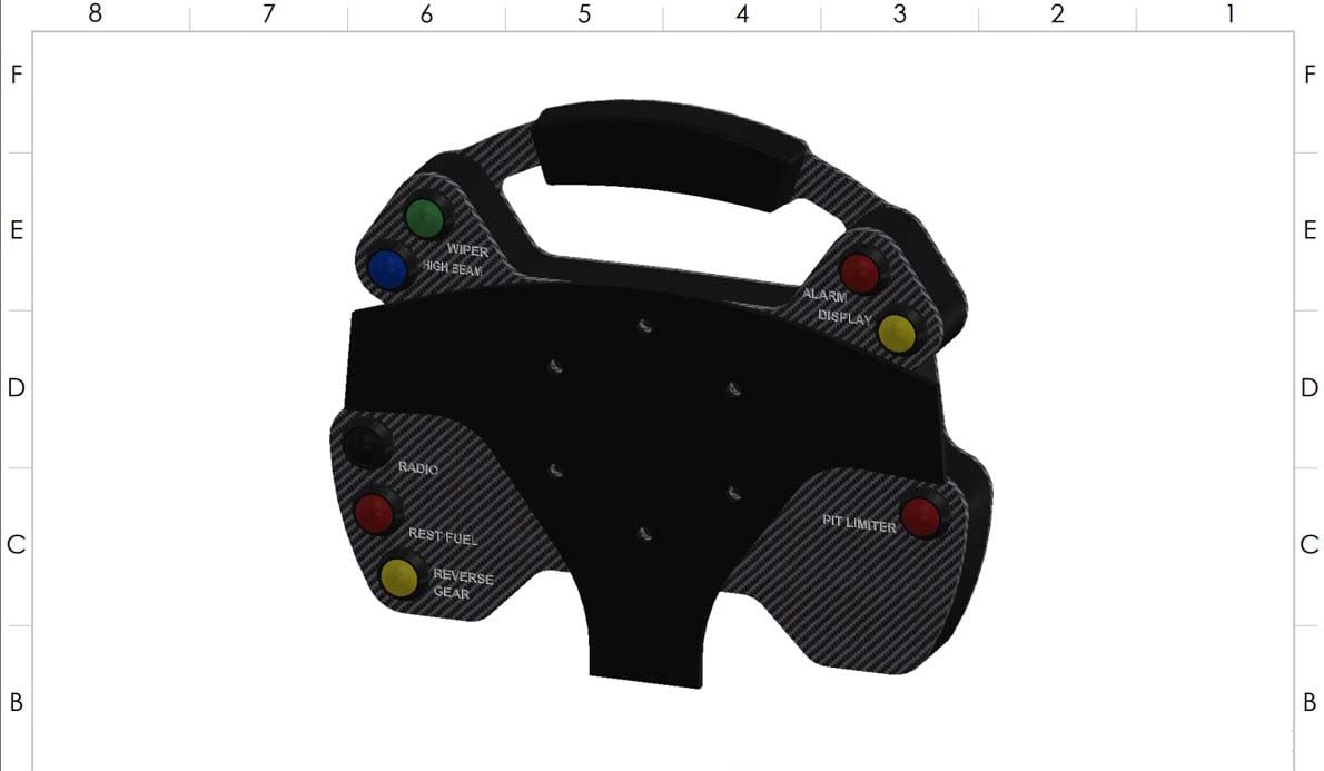
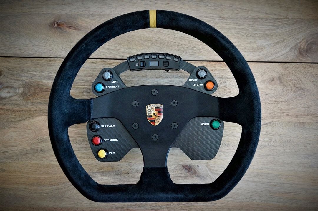
I decided early on I would have the shift light on a second steering wheel instead of being mounted to the dash. This allowed me to run with one wheel designed for the track and one wheel designed for the street.
It's nice to have options!
Here's the standard 991 Cup Car plate we started with.
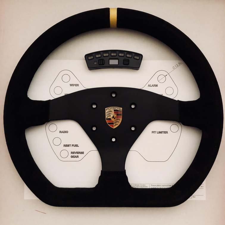
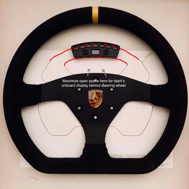
Here is one of the later stage drafts.
You'll see I mounted it on a bridge across the rear cover plate raised high enough that I could see the OBC between the Shift Light and the top of the steering wheel hub. It's also low enough for hand shuffling.
I learned from making my last wheel some tricks to simplify the wiring including running ground in series on all switches. This is more easily done with an enclosure too. I'll go into some of the other functions in another thread and focus on the shift light here.
First I mock mounted the shift light and drilled a hole in the plate to feed the wiring through. The red wire is 12V, blue is RPM and black is ground. The white green and purple wires coming from the shift light are for different input/output channels. I used one to change profiles on the shift light. In this pic though they are all tied back until I confirmed with Tony at Ecliptech how to do that properly.
Next I'll go into how I wired for the OBC 'Alarm' clear switch and how I wired for PASM and PSM switches.
I'll end the steering wheel saga here with the OBC wiring and PASM/PSM switches.
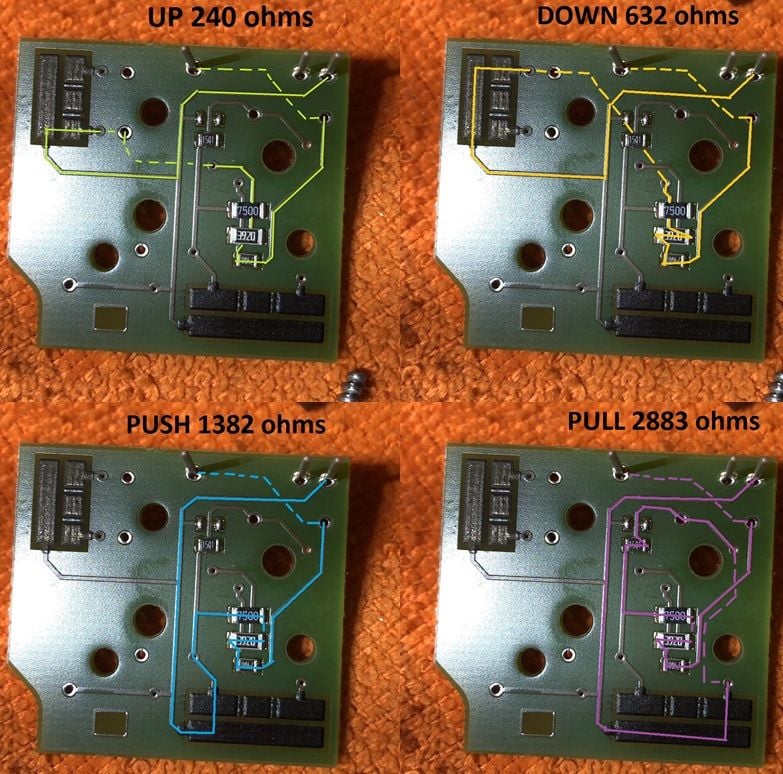
I tapped the OBC module similarly to the indicator/high beam module.
It was disassembled and I mapped the PCB circuits:
Like before there are terminal leads protruding from the board so no soldering is required. Just add a jumper to the lead and drill a tiny hole in the module for the wiring.
Since the wiring would be a cakewalk I thought about adding a 4 way joystick instead of a momentary switch to be able to control every input of the OBC from the steering wheel, but thought trying to use a small joystick at speed was not ideal and didn't want to over complicate things.
So I only wired 'PUSH' to the 'ALARM' function on the wheel. This would clear any TPMS warnings from starting sessions with cold tires and thusly low PSI.
Mapping the PCB for the PASM and PSM switches took an age. A lot of the circuits led underneath components which made it difficult to track which terminal was for which function even with a wiring diagram. After mapping and measuring resistance I had everything ready.
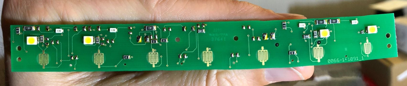
I won't be posting the mapping for this, but here is what your module looks like disassembled:
This only looks crooked because I used 'panorama' to photograph it in macro. So the rolling shudder didn't align it well with my shaky hand.
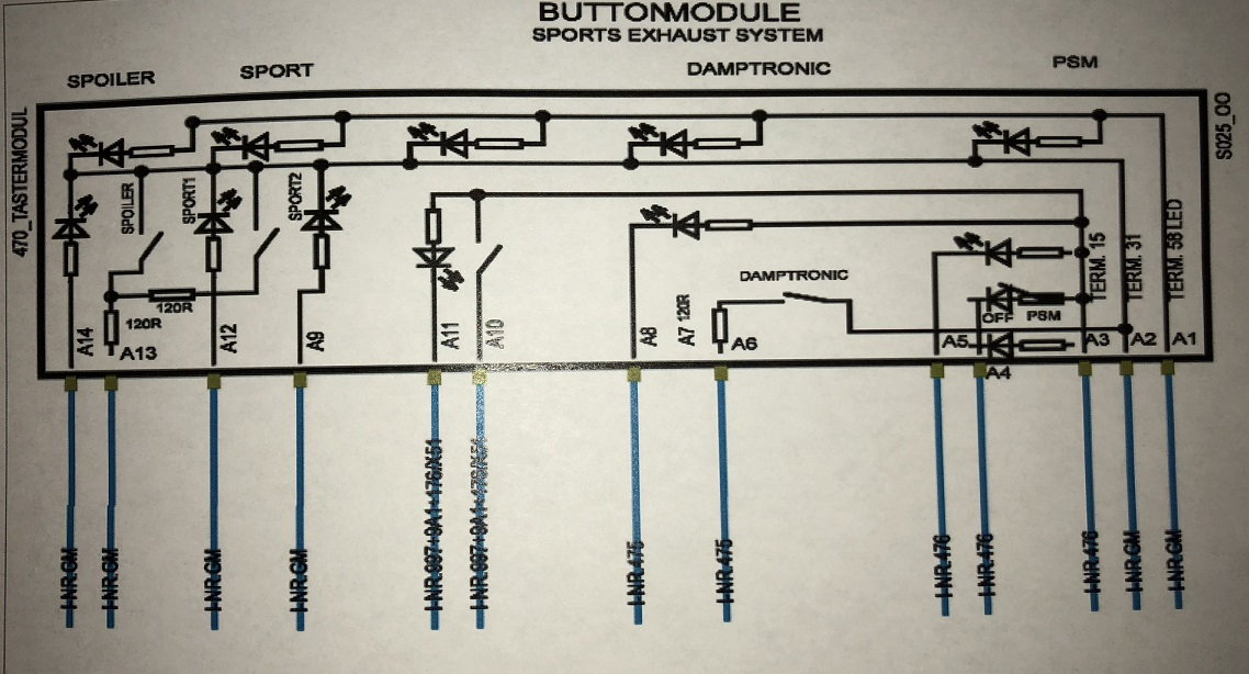
These PCBs are customized based on options stored in your VIN which is why dealers require the VIN when your retrofit an accessory like PSE or Sport(+). Some of the circuits are obviously missing crucial resistors. So, any of you just trying to slap on an extra button to get something like Sport to work are out of luck.
The OEM wiring diagram for our button modules.
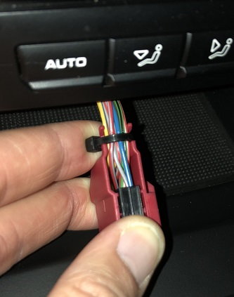
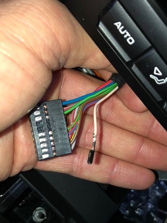
There were no terminal leads on this PCB so I tapped the wiring harness and the respective wires for each function
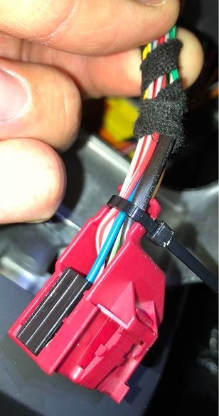
One link in the PASM chain.
All wired into the OEM harness.
The PSM and PASM wires were fed through a custom harness to the clockspring similarly to how the steering wheel modules were wired.
.....and Voila!
I've had quite a few requests for a video demo which I'll post soon, but for now...
On to the next project...
Quick (terrible quality) preview shot of the new interior. All black alcantara! I'll post an SLR side-by-side with the previous interior when this rain subsides.
Just outstanding. The attention to detail for us to follow along is mucho appreciated whether we do these mods or not. My only regret with my 7.2S, was not getting the white GTS i had the chance to get (albeit 20k more)....
anyways, love your thread
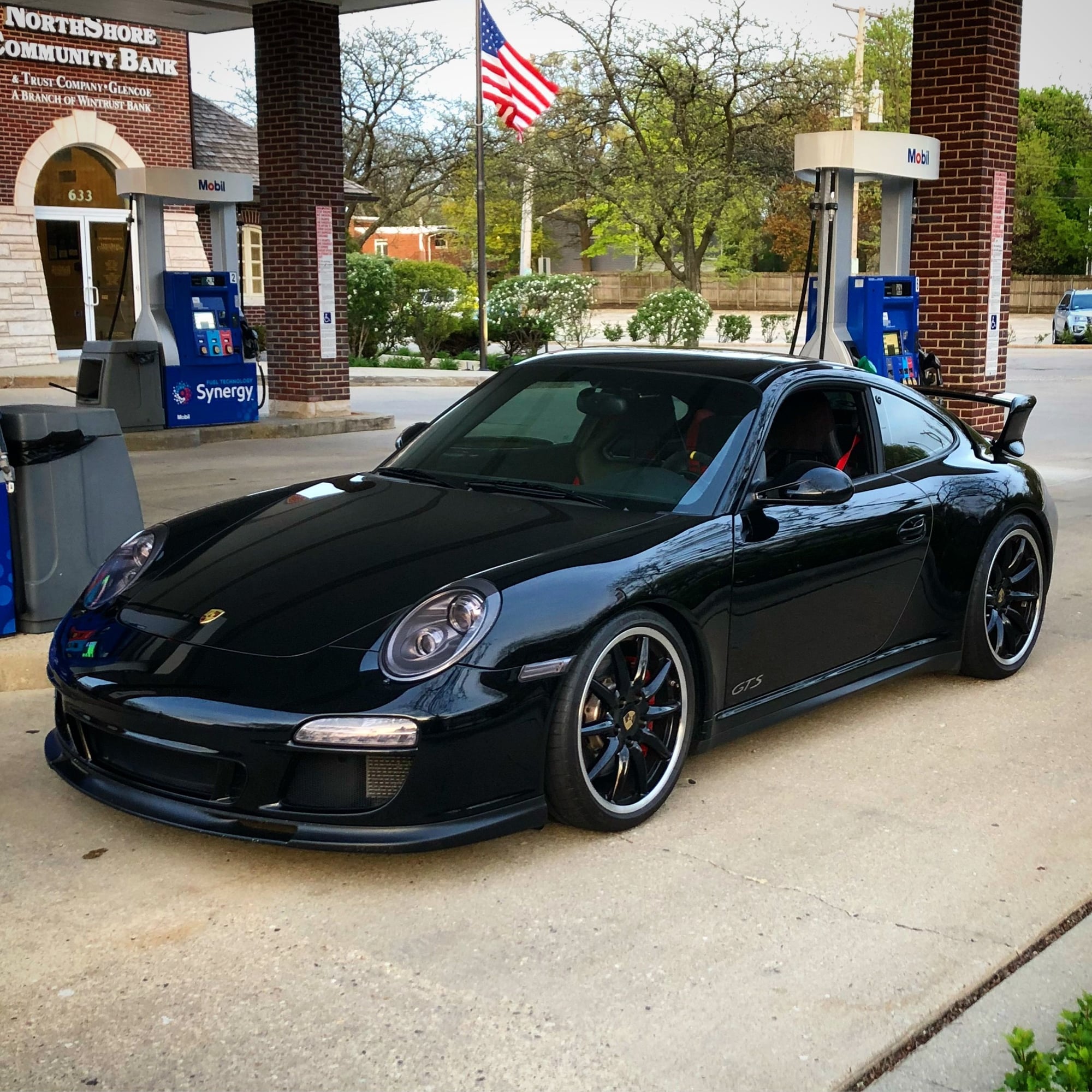
We had one day above 50 degrees without rain recently and I took the opportunity for a drive with a local car club:
An obligatory golden hour gas station shot.
Originally Posted by The Beast
All I can is WOW!
Originally Posted by mikes70
Just outstanding. The attention to detail for us to follow along is mucho appreciated whether we do these mods or not. My only regret with my 7.2S, was not getting the white GTS i had the chance to get (albeit 20k more)....
anyways, love your thread
Thank you! I wish I had more time to be more detailed and really make these step-by-step DIYs.
The fact that these circuits are only differentiated by resistance makes these extremely simple. Moreover, it simplifies the wiring needed thereby reducing weight compared to relay circuits. Too bad one Bose subwoofer probably cancels out any weight savings by reduced wiring. Oh well.
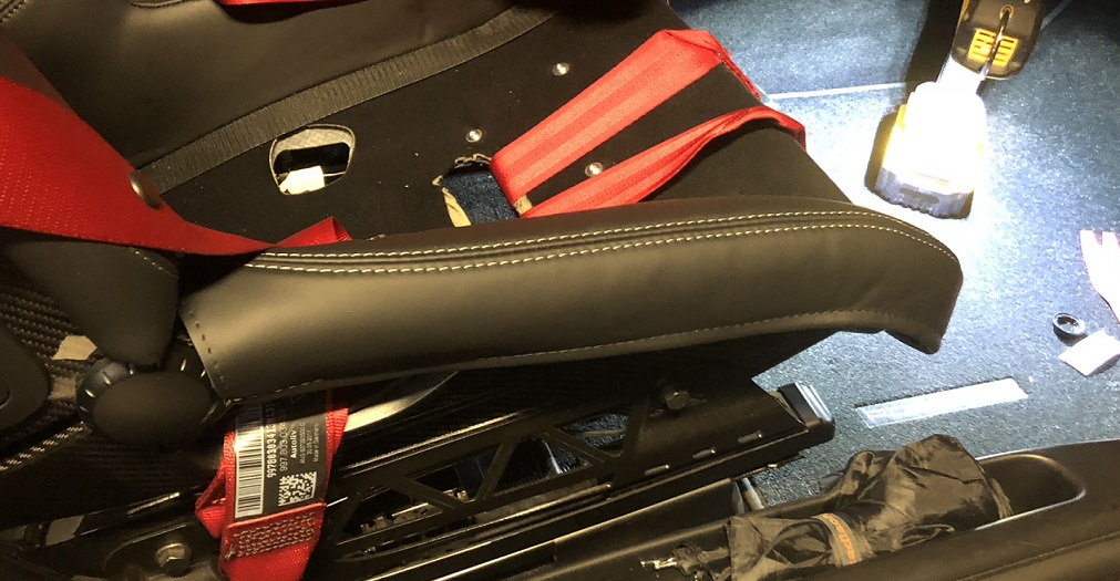
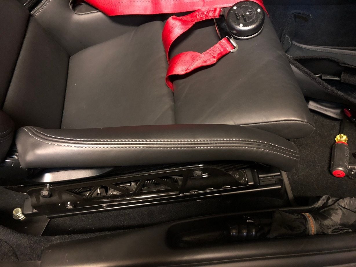
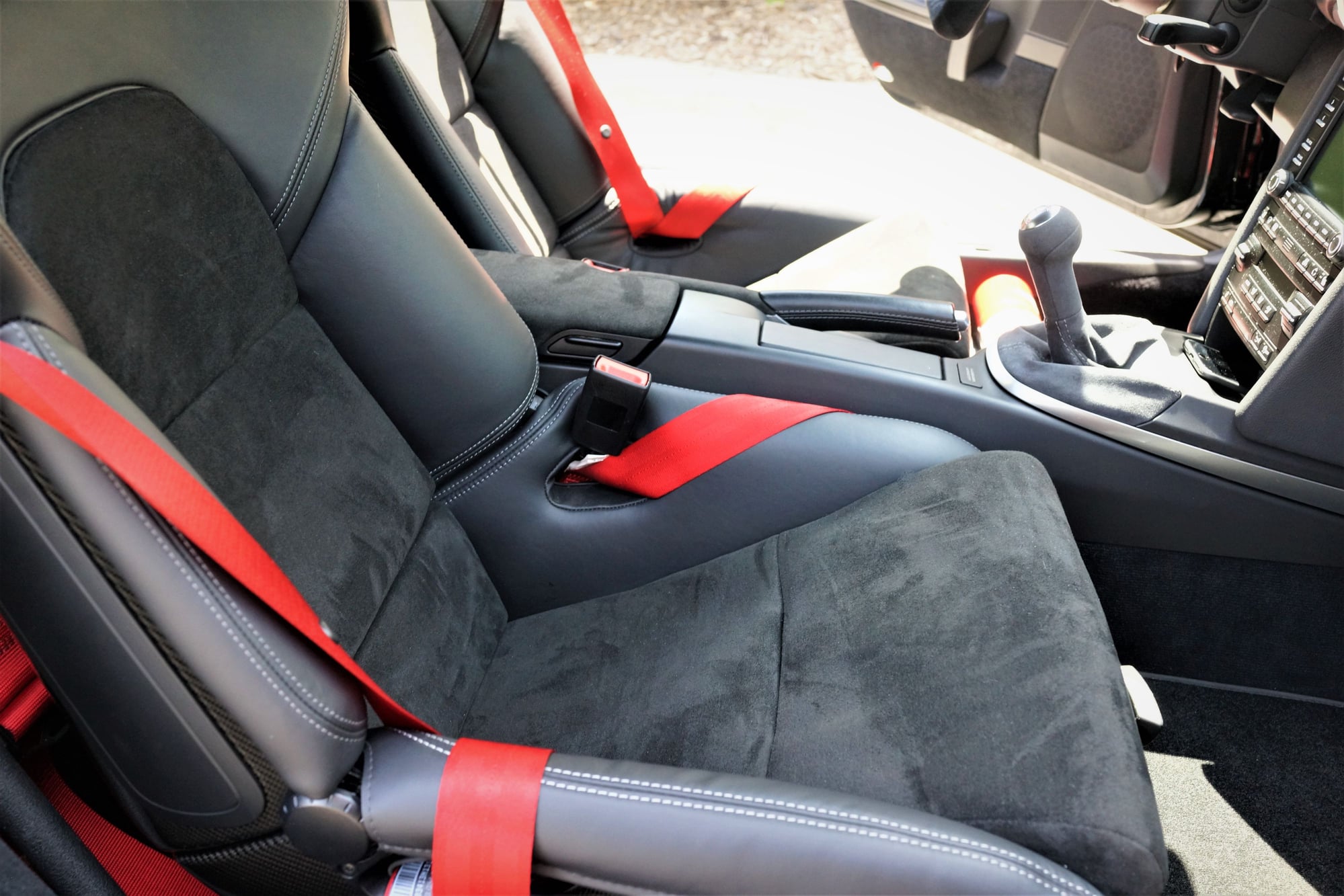
]I installed Crazy Eddie's bolster covers for my GT2 seats tonight. These things are works of art. Unless you were really looking you'd never even know they were covers. I like them so much he and I are scoping another project for these seats that I really hope pans out. More on that to come.
I'll end the steering wheel saga here with the OBC wiring and PASM/PSM switches.
I tapped the OBC module similarly to the indicator/high beam module.
It was disassembled and I mapped the PCB circuits:
Like before there are terminal leads protruding from the board so no soldering is required. Just add a jumper to the lead and drill a tiny hole in the module for the wiring.
Since the wiring would be a cakewalk I thought about adding a 4 way joystick instead of a momentary switch to be able to control every input of the OBC from the steering wheel, but thought trying to use a small joystick at speed was not ideal and didn't want to over complicate things.
So I only wired 'PUSH' to the 'ALARM' function on the wheel. This would clear any TPMS warnings from starting sessions with cold tires and thusly low PSI.
Mapping the PCB for the PASM and PSM switches took an age. A lot of the circuits led underneath components which made it difficult to track which terminal was for which function even with a wiring diagram. After mapping and measuring resistance I had everything ready.
I won't be posting the mapping for this, but here is what your module looks like disassembled:
This only looks crooked because I used 'panorama' to photograph it in macro. So the rolling shudder didn't align it well with my shaky hand.
These PCBs are customized based on options stored in your VIN which is why dealers require the VIN when your retrofit an accessory like PSE or Sport(+). Some of the circuits are obviously missing crucial resistors. So, any of you just trying to slap on an extra button to get something like Sport to work are out of luck.
The OEM wiring diagram for our button modules.
There were no terminal leads on this PCB so I tapped the wiring harness and the respective wires for each function
One link in the PASM chain.
All wired into the OEM harness.
The PSM and PASM wires were fed through a custom harness to the clockspring similarly to how the steering wheel modules were wired.
.....and Voila!
I've had quite a few requests for a video demo which I'll post soon, but for now...
On to the next project...
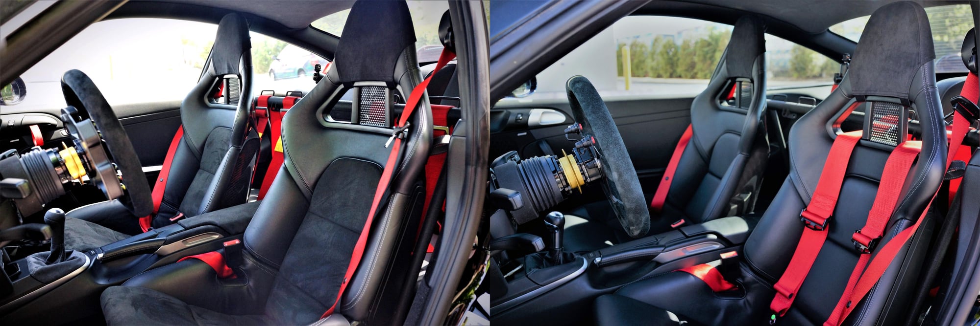
Finally got the car out but these were the best pics I could get today of the new interior.
The never tiring Crazy Eddie made the new black Alcantara GT2 Sport Bucket seat inserts for me. Yeah not the most exciting choice but hard to do a fun tartan interior on a black car.
He also made the black Alcantara center console lid and with some extra fabric, I knocked out the e-brake banana.
The black Alcantara shifter is OEM Porsche.
These pics make them looked a bit washed out but here's a good side by side shot after trying to balance each shot.
I'll get better shots at some point this month.


 05-05-2018 | 06:02 PM