Finally finishing AOS/RMS/IMS
 12-28-2013, 07:28 PM
#1
Pro
Thread Starter
So after a full year of being out of commission I'm finally completing this project. To briefly recap a year ago my clutch started feeling funny and a few weeks later the transmission would not go into gear, namely reverse and first and eventually any gear. So I parked it till I had the money to fix it.
Around summer I purchased parts to replace the flywheel, clutch, slave cylinder, AOS, and IMS bearing. Some of the parts I sourced from Pelican, some from Suncoast, the flywheel from Amazon - they had a killer price.
So I removed the transmission and started with the AOS. I gotta' be honest here: the learning curve for working on this car is steep. Working on the thing is like peeling an onion. Parts have to come off and be installed in a certain order and many will only come off one way with this particular tool used precisely in this manner, or one of the notorious special tools. If I had to do it all again I would have just pulled the engine and been done with it. That's my official recommendation.
So I did the AOS. Now that dark and cavernous area under the intake manifold and tucked back in the hole that serves as an engine compartment no longer holds any mystery - I have delved into all its secrets and emerged on the other side worse for wear, but wiser and confident.
Next I tackled the IMS with a replacement from LNE. Seemed simple enough but here is where peeling the onion brings tears to your eyes. I determined to follow the instructions and loosen the third chain tensioner, remove it actually to replace the o-ring and washer per recommendations. To remove this tensioner one has to remove the AC compressor. The front two bolts are easy enough but the rear can only be accessed with a socket on an extension of a precise length and located blindly by inserting the socket and extension between the runners of the intake until it falls onto what must be the bolt head.
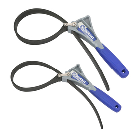
Once the compressor is removed the tensioner is visible, but there's no way to access it without peeling back a few more layers. There's a sort of bracket mounted over the top of the tensioner that must be removed to reach the tensioner, but Porsche decided to use internal hex head bolts for this bracket and there is no way to fit a socket or hex wrench to loosen them because the power steering line, which the bracket secures, is in the way. SO the power steering line must be disconnected from the pump but - oh, wait - that can't be accessed with a wrench or crows foot either because the PS pulley blocks access. Now there's no way to secure the pulley so the bolts can be loosened so I had to rig the fan belt to hold the pulley enough to loosen the bolts. So now I've removed the pulley and the hose just to be able to insert a hex wrench, no access for a socket, into the bolt heads and remove the bracket. Way to go Porsche!
Here's what happened when I tried to reinstall the pulley using vise grips to hold it:
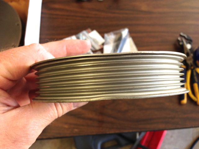
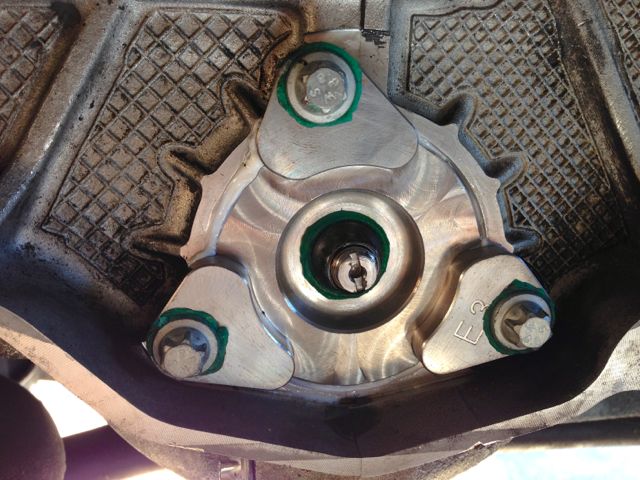
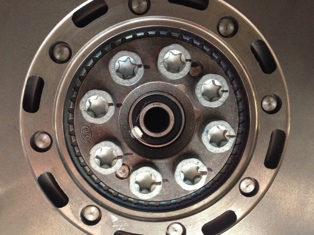
I didn't realize is was so delicate. I have a new one on order. The only other issue I had was trying to figure out how to properly torque the center nut. LNE decided to change the nut size from a stock 13mm to 11mm, so the special torque wrench adapter I purchased from Porsche to torque the nut was useless as well as the procedure outlined by Porsche detailing how to hold the bearing stud stationary with a screwdriver while torquing the nut with the tool. So now I'm searching everywhere looking for a 11mm tool that will allow me to huld the stud while torquing the nut but none are to be found - anywhere. I emailed LNE and after a few back-and-forths a link was provided to a video that showed the nut being torqued without holding the stud. Apparently one only has to snug the nut securely with a box-end and then the stud will not turn when the nut is torqued. I think if a company is going to change the the established procedure for installing a part they should provide something more descriptive in their written instructions than "...the nut can be torqued...". It would have certainly been helpful for me.
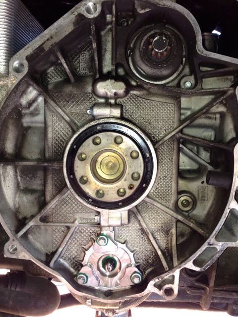
Once the IMS was in the RMS came out and the new seal installed without a hitch with my handy-dandy RMS install tool. I wish every task went so smoothly. After that the new flywheel, clutch disk, and pressure plate went on:
Around summer I purchased parts to replace the flywheel, clutch, slave cylinder, AOS, and IMS bearing. Some of the parts I sourced from Pelican, some from Suncoast, the flywheel from Amazon - they had a killer price.
So I removed the transmission and started with the AOS. I gotta' be honest here: the learning curve for working on this car is steep. Working on the thing is like peeling an onion. Parts have to come off and be installed in a certain order and many will only come off one way with this particular tool used precisely in this manner, or one of the notorious special tools. If I had to do it all again I would have just pulled the engine and been done with it. That's my official recommendation.
So I did the AOS. Now that dark and cavernous area under the intake manifold and tucked back in the hole that serves as an engine compartment no longer holds any mystery - I have delved into all its secrets and emerged on the other side worse for wear, but wiser and confident.
Next I tackled the IMS with a replacement from LNE. Seemed simple enough but here is where peeling the onion brings tears to your eyes. I determined to follow the instructions and loosen the third chain tensioner, remove it actually to replace the o-ring and washer per recommendations. To remove this tensioner one has to remove the AC compressor. The front two bolts are easy enough but the rear can only be accessed with a socket on an extension of a precise length and located blindly by inserting the socket and extension between the runners of the intake until it falls onto what must be the bolt head.
Once the compressor is removed the tensioner is visible, but there's no way to access it without peeling back a few more layers. There's a sort of bracket mounted over the top of the tensioner that must be removed to reach the tensioner, but Porsche decided to use internal hex head bolts for this bracket and there is no way to fit a socket or hex wrench to loosen them because the power steering line, which the bracket secures, is in the way. SO the power steering line must be disconnected from the pump but - oh, wait - that can't be accessed with a wrench or crows foot either because the PS pulley blocks access. Now there's no way to secure the pulley so the bolts can be loosened so I had to rig the fan belt to hold the pulley enough to loosen the bolts. So now I've removed the pulley and the hose just to be able to insert a hex wrench, no access for a socket, into the bolt heads and remove the bracket. Way to go Porsche!
Here's what happened when I tried to reinstall the pulley using vise grips to hold it:
I didn't realize is was so delicate. I have a new one on order. The only other issue I had was trying to figure out how to properly torque the center nut. LNE decided to change the nut size from a stock 13mm to 11mm, so the special torque wrench adapter I purchased from Porsche to torque the nut was useless as well as the procedure outlined by Porsche detailing how to hold the bearing stud stationary with a screwdriver while torquing the nut with the tool. So now I'm searching everywhere looking for a 11mm tool that will allow me to huld the stud while torquing the nut but none are to be found - anywhere. I emailed LNE and after a few back-and-forths a link was provided to a video that showed the nut being torqued without holding the stud. Apparently one only has to snug the nut securely with a box-end and then the stud will not turn when the nut is torqued. I think if a company is going to change the the established procedure for installing a part they should provide something more descriptive in their written instructions than "...the nut can be torqued...". It would have certainly been helpful for me.
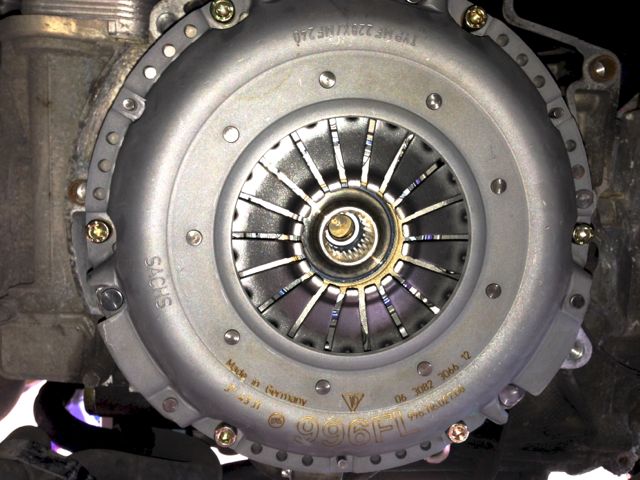
Once the IMS was in the RMS came out and the new seal installed without a hitch with my handy-dandy RMS install tool. I wish every task went so smoothly. After that the new flywheel, clutch disk, and pressure plate went on:
 12-28-2013, 07:40 PM
#2
Pro
Thread Starter
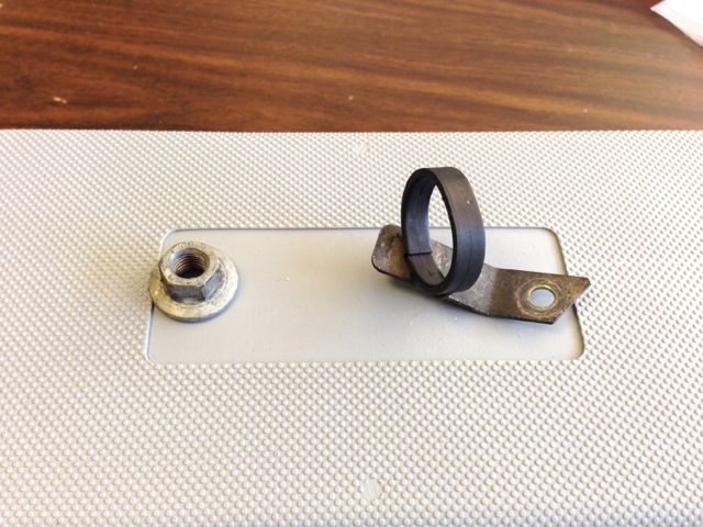
Now I come to the "parts left over" section of my journey. I have a nut and a hose bracket I can't find a place for of remember where they came from:
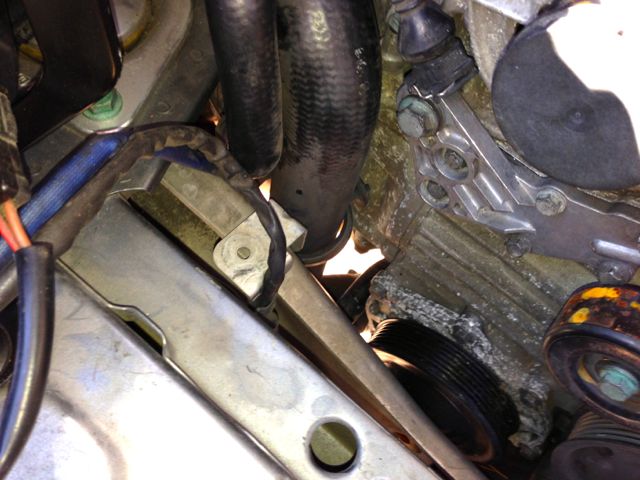
Perhaps someone can jog my memory. I also have a place where it appears something was attached but what I don't know. It's the hole in the center of the pic next to the wires (left side below the air pump on the engine crossmenber):
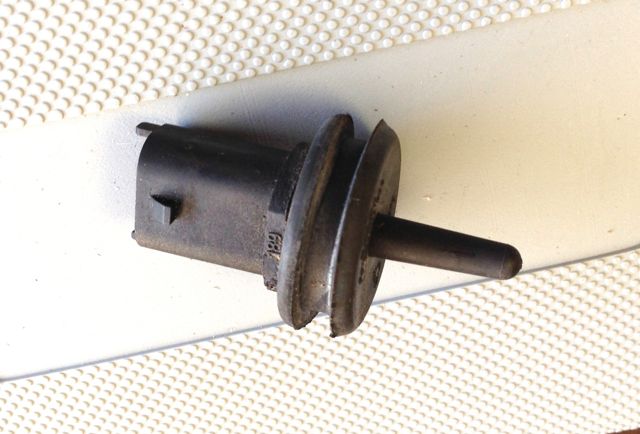
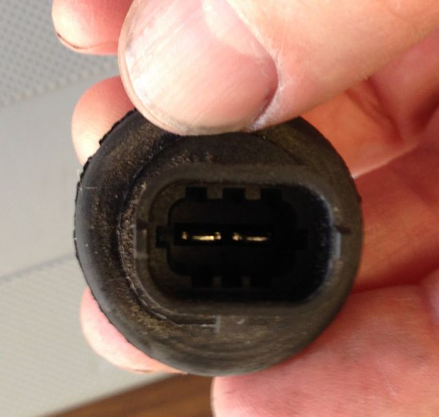
As I went along most of the bolts I put in baggies or immediately back in the hole they came out of, but these are the inevitable stragglers that I missed. I also found some type of sensor tucked behind some wiring on the right side of the engine bay. It looks like a temp sensor perhaps with a grommet to fit in a hole? I couldn't find any unattached wires that might fit in the connector:
Perhaps someone can jog my memory. I also have a place where it appears something was attached but what I don't know. It's the hole in the center of the pic next to the wires (left side below the air pump on the engine crossmenber):
As I went along most of the bolts I put in baggies or immediately back in the hole they came out of, but these are the inevitable stragglers that I missed. I also found some type of sensor tucked behind some wiring on the right side of the engine bay. It looks like a temp sensor perhaps with a grommet to fit in a hole? I couldn't find any unattached wires that might fit in the connector:
12-28-2013, 07:53 PM
#3
Pro
Thread Starter
Tasks still to be completed:
- Install transmission - done
- Install slave cylinder - done
- Attach axles - waiting for tool - done
- Install transmission mount - done
- Reattach linkage - done
- Install crossmember and brace - done
- Replace transmission fluid - done
- Replace brake/clutch fluid and bleed - done
- Replace engine oil and filter - done
- Tighten motor mounts - done
- Reinstall shifter console - done
- Buy vacuum hose and reattach - done
- Replace PS vent hose - done
- Reattach sway bar - done
- Repair rear tire (nail) - done
- Reattach undertrays - done
- Install PS pulley - done
- Install fan belt - done
- cross fingers - successful!
Last edited by sandersd; 01-17-2014 at 10:11 PM. Reason: update
12-28-2013, 08:33 PM
#4

If I had to do it all again I would have just pulled the engine and been done with it. That's my official recommendation.
The metal bracket with the plastic hose holder is bolted to the #1 intake tube bolt (driver side/front). The SAI hose goes in the clamp.
The sensor looks like the engine bay temp sensor w/grommet. Goes between intake runners on 4-6 side. Look at #12 in pic.
The nut looks like the ones on the elect. term bracket, 4-6 side or TB bracket lower left on PS pump.
Like you said, it really helps if you put fasteners right back where they came from as you remove parts, take photos, and make notes.
This will be easy for you next time.
Last edited by KrazyK; 04-27-2016 at 10:25 AM.
12-29-2013, 10:12 AM
#6
Pro
Thread Starter
Trending Topics
12-29-2013, 10:23 AM
#8
Rennlist Member

Join Date: Apr 2013
Location: Argyle, Texas
Posts: 41
Likes: 0
Received 0 Likes
on
0 Posts
I believe that if I am looking at the picture correctly, you will find that your air box has a plastic protrusion that drops in to the hole to position it ( the air box). There should be a rubber grommet in the hole to prevent the box from sliding around.
12-29-2013, 11:42 AM
#9
Former Vendor

The sensor that you posted the pic of is the engine bay temperature sensor. It slides into a position on the 4-6 intake runners near the center. The IPB above shows it as #12
12-29-2013, 08:03 PM
#10
Pro
Thread Starter
Thanks Ed but I think you're looking at the hole in the bottom of the pic. That's a little higher on the body sheet metal. This hole is on the engine crossmember in the center of the pic with the wire next to it.
12-30-2013, 06:37 AM
#11
Rennlist Member
Join Date: Apr 2013
Location: Argyle, Texas
Posts: 41
Likes: 0
Received 0 Likes
on
0 Posts
Sorry.
I'll try again, the hole is actually in a small sheet metal bracket attached to the crossmember. It is an attachment point for a small plastic clip. The clip has a conical end that snaps in to the hole and clamp on top. Two wires going to the back of the engine compartment are held in place by the clamp.
I took a couple of pictures with my cell phone and will try and post them later...have to head in to the office shortly.
12-30-2013, 11:57 AM
#14
KrazyK, do you see anything attached to the hole on the engine crossmember?