When you click on links to various merchants on this site and make a purchase, this can result in this site earning a commission. Affiliate programs and affiliations include, but are not limited to, the eBay Partner Network.
Tips or tricks for reassembling shift slider operating sleeve assembly?
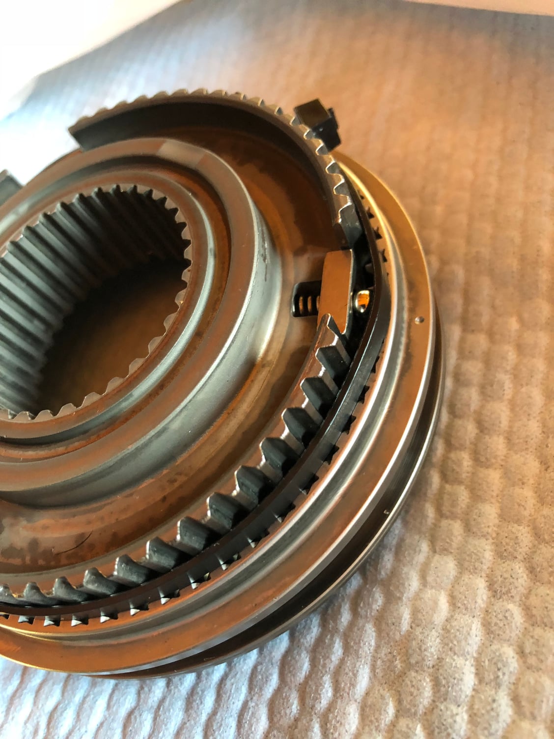
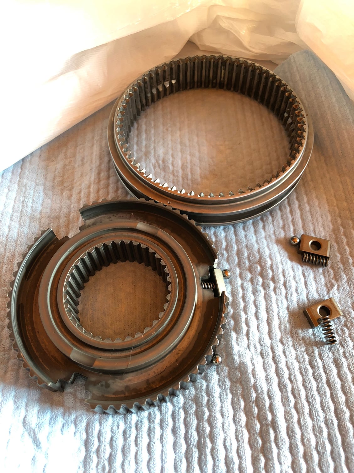
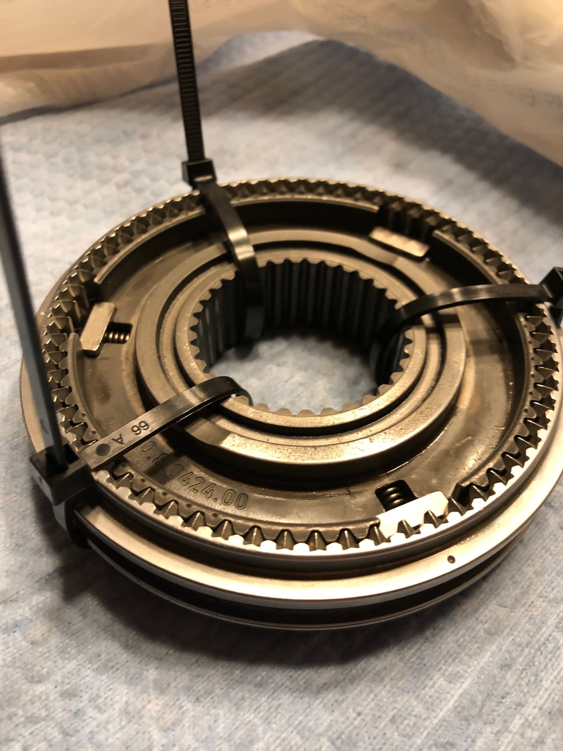
I’m reassembling my transmission after replacing the 2nd gear synchros, and as expected, the shift slider assembly came apart, leaving me both parts of the slider, three rectangular keys, three springs, and three tiny detent ball bearings. Thankfully none were lost, but I am struggling with reassembly. I can’t get the three spring loaded pieces into place with the ball bearings. Any tips or tricks you could share to help me along? It is super fiddly and frustrating...
Wow... sounds like a real pita. I don�t think there are many here that haveactually had their tranny apart. There was a great thread a few years ago about someone who did their own rebuild. I think you need to find that thread and reach out to it�s author. Good luck and hang in there - you�ll figure it out (hopefully someone with knowledge will chime in).
I�m reassembling my transmission after replacing the 2nd gear synchros, and as expected, the shift slider assembly came apart, leaving me both parts of the slider, three rectangular keys, three springs, and three tiny detent ball bearings. Thankfully none were lost, but I am struggling with reassembly. I can�t get the three spring loaded pieces into place with the ball bearings. Any tips or tricks you could share to help me along? It is super fiddly and frustrating...
Get a tall 13 gallon kitchen garbage bag and/or can and work inside of it so that flying springs and detent ***** are not lost. Then with a large zip-tie around the inner hub load the springs, stones, and *****, then evenly slide into outer slider carefully pushing manily on the stones.. Inner hub orientation is also nessesary.
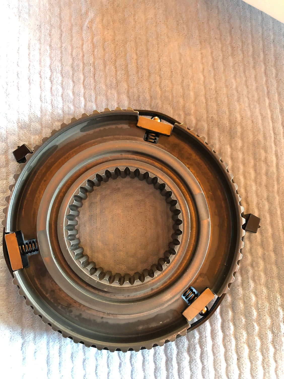
So assuming that the picture with the springs and ***** installed is what you should end up with? I.e. pre-disassembly? - Wait EDIT: Can see you've cable tied them in place!
I've had similar issues on a much smaller scale with 90's Mercedes window switches ugh anything with a spring and a ball bearing is a complete PITA...
Maybe an extra set of hands can help? I.e. 4 people - 3 to do each spring and one to install the casing?
Still open to ideas. I spent the better part of five hours trying, and never got it. Those ***** and springs sure do launch! So frustrating.
Tighten up the tie-straps as much as possible, use the syncro ring that fits up against the stones to help push them in along with the inner hub, you may have to press in on the ***** a little to get them started going in..You can do it !!! Just takes a little finesse..
Could a large metal hose clamp be used instead of the zip ties? I'm picturing something like a piston ring compressor setup, you know where you could then gently tap the hub out of the hose clamp and into the slider. Seems like the zip ties are deflecting a bit from the spring pressure.
Good idea. I actually tried a hose clamp yesterday, and it was great for the reason you mention, it didn't deflect and did a better job of compressing the detent ball bearings. Unfortunately, it didn't work well enough. The "stones" (as they are named in the PET - rectangular blocks with a hole in the middle) deflected upward during installation, and it made it hard to access the detent ball bearings, which is key to getting this done.
I may have to combine some ideas.
The addition of using the synchro as the thing used to evenly push down on it might make all the difference!
I may modify the hose clamp with some small drilled holes - smaller than the detent ball so it can't fly out, but large enough to get a small tool (punch with a concave tip?) into. That way, I can get preserve the rigidity of the hose clamp, but still be able to manipulate the detents, as I push down with the synchro cone.
I also have a ring compressor that I could try too if the others don't work out.
Zero experience here but it looks like a fun problem. How about some thin shims between the ***** and the hose clamp to push the ***** more inward? Any chance to install the springs last?
Not sure if there's enough clearance once the two rings mate together but could you use for each block a piece of safety wire or similar, through the middle and over each end or the block, twist the wire to pull it tight?
edit: maybe not... I need to look at the manual, but looking at the photos I posted, I may have installed the inner hub backwards. I think those smaller dimples go on the opposite side from the marks on the outer hub. Sigh... I guess the up side is that I’ve done it once, there isn’t any reason I can’t do it again.
Thanks to everyone for the support, guidance and advice.
I told my kids that my vision of hell would be me forced to try to assemble this thing for eternity. If I never do it again, it will be too soon.
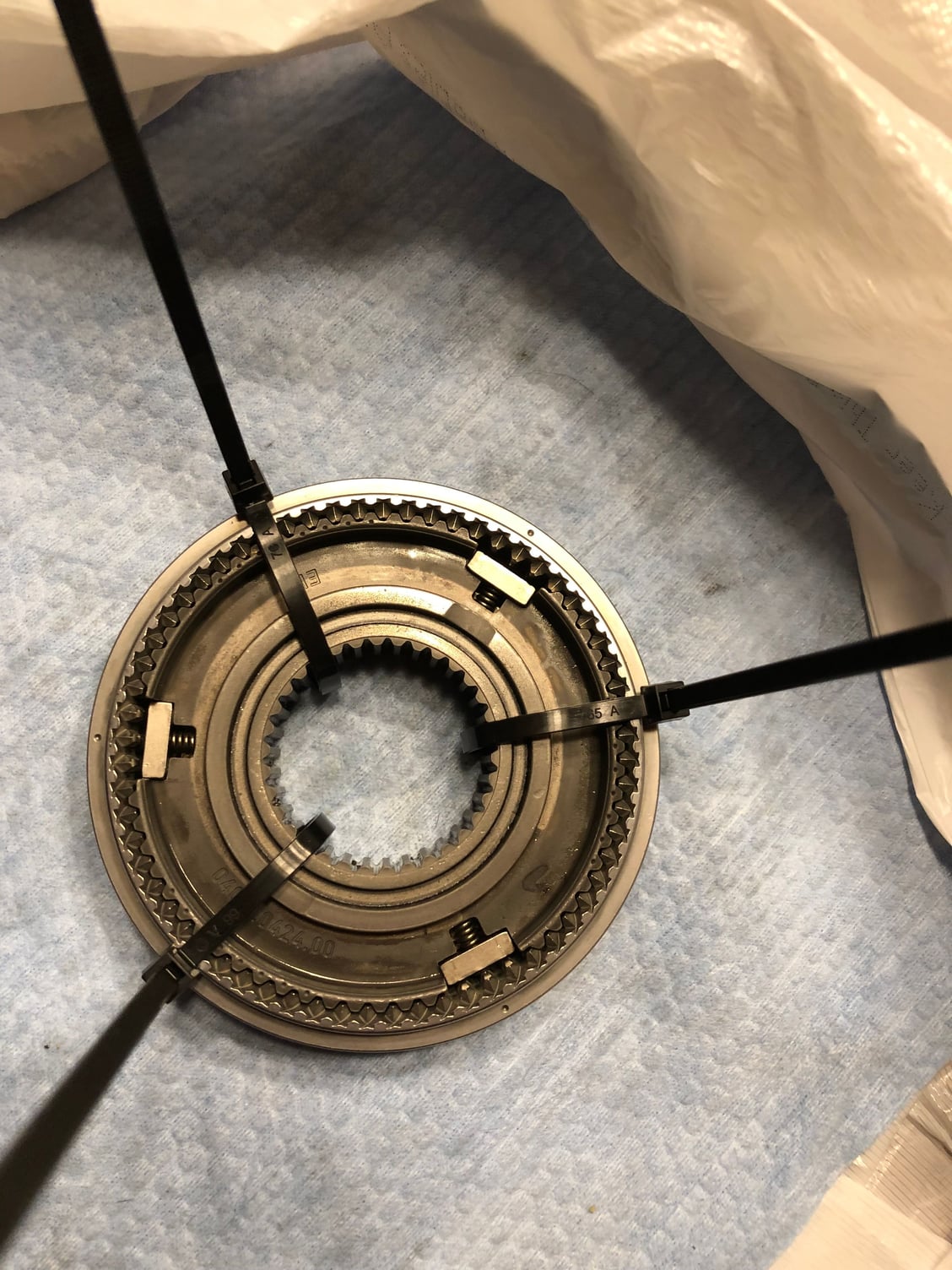
What finally worked for me was not very elegant. I held the outside ring in my left hand, with the synchro cone against the left side of the inner sliding hub, with the hub offset to the right so I could load the spring, stone, ball assemblies one at a time (using a large dimpled center punch to push the ball in). I got the first one in, centered it (like it was in Neutral), then carefully pushed it toward the first gear side as far as it could go without launching the parts, all the while I held the synchro cone against the left side to prevent the parts from launching that way. Then I put the second set in, centered it to neutral, then using the synchro cone, pushed it back toward the first gear side as far as it would go without launching bits. Then, holding everything with a vicelike grip in my left hand, I did the same with the third. I carefully pushed all three (of the spring, ball, stone) sets back to the neutral (centered in the groove) position, and quickly had my daughter throw three zip ties on the whole thing to hold it together.
I sincerely hope I never have to do this again, and wish anyone else luck if they have to.
My best advice is to make sure they don’t ever come apart when you dissasemble the gear stack.
Huge props to the pros who do this kind of thing regularly.
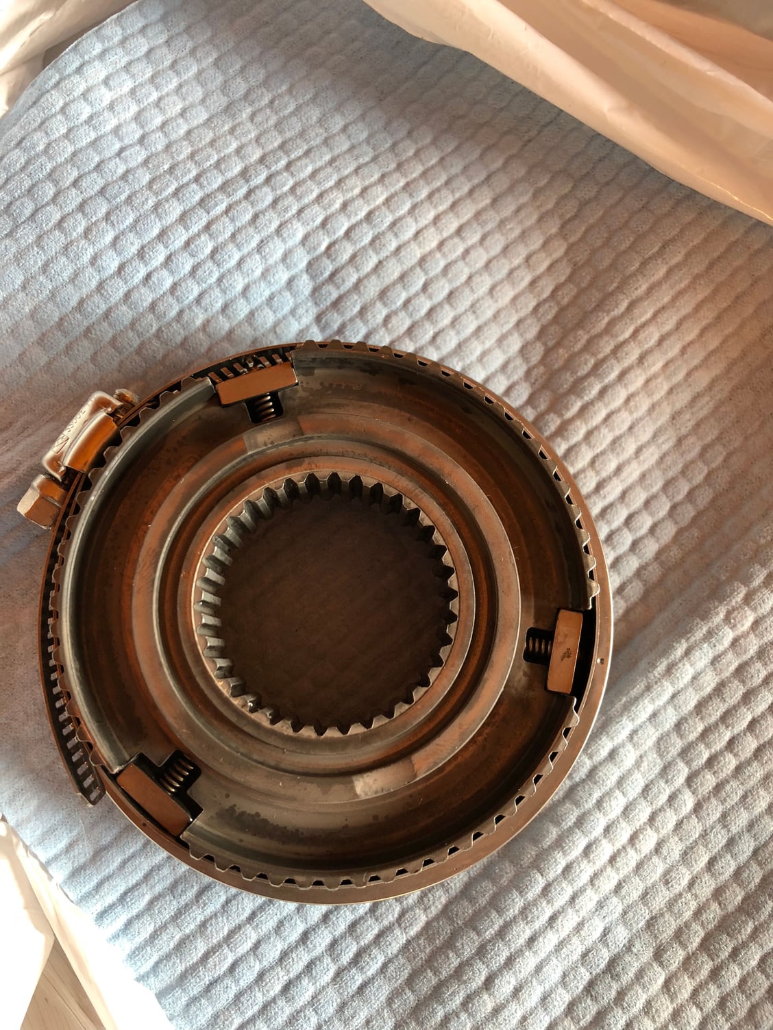
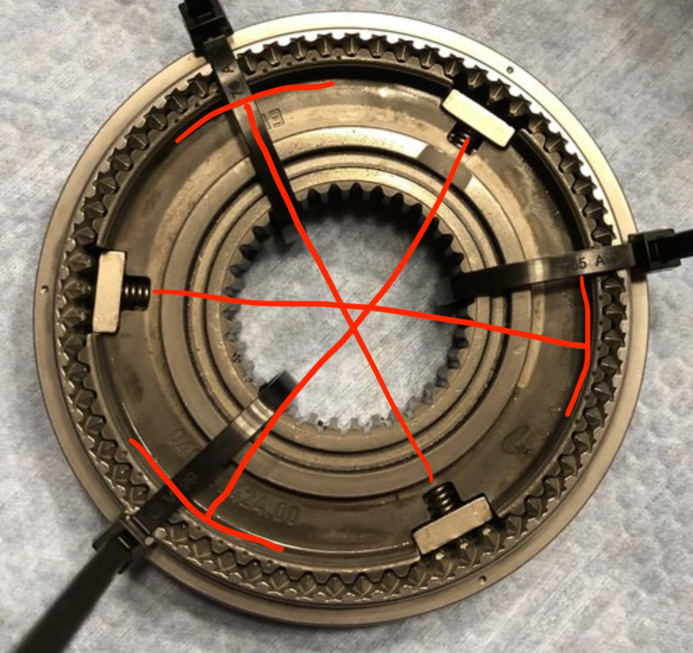
Do the series of small cast in dimples on one side indicate anything meaningful about orientation (like should the small dimples face toward the 1st or 2nd gear side, for example)? The outer sliding sleeve is directional (groove faces toward 1st gear), so it has me wondering.
The only manual I have doesn't mention this detail, or any other indicating orientation of the inner hub. On visual inspection, the sides appear symmetrical, I'm not sure about the grooves and teeth since they are no longer visible once installed.
There are three sets of multiple dimples in the inner hub. They seem to be oriented 180 degrees from the spring/ball/stone assemblies:
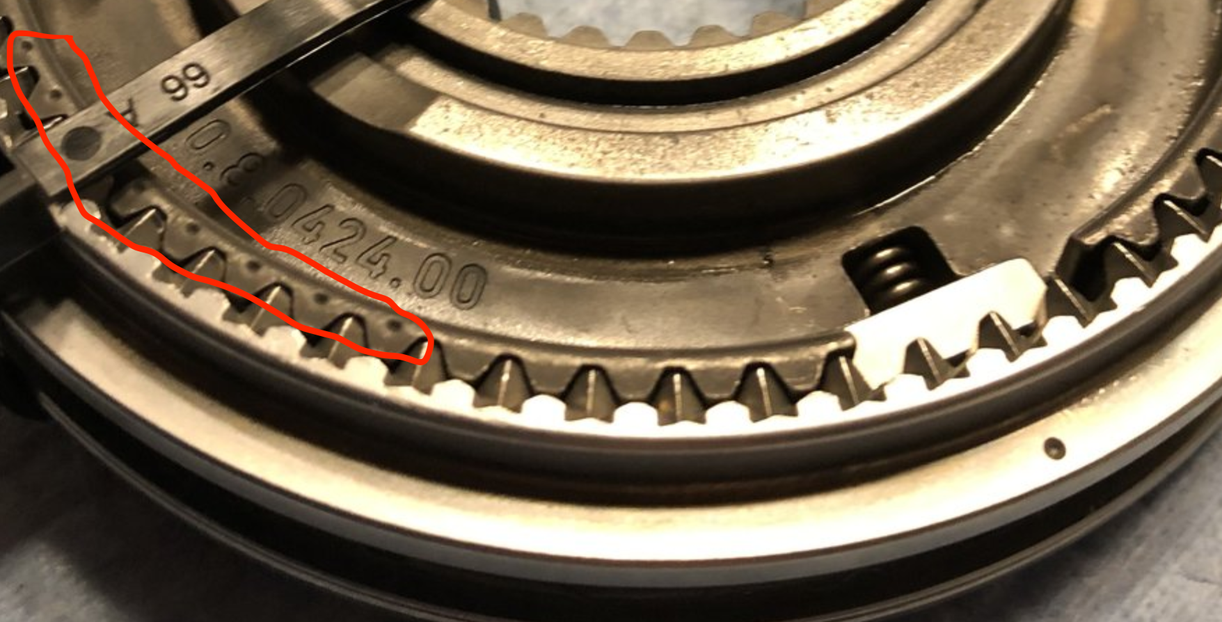
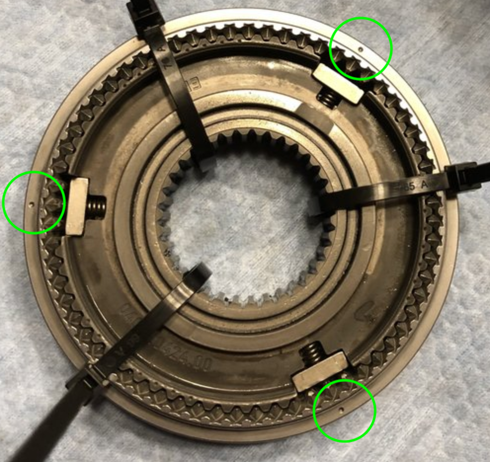
And just for the sake of clarity, I am not talking about these (green circled) larger dimples in the outer sleeve. These are marks to indicate where the neutral detents are in the inner circumference of the hub, and are used to orient the spring/ball/stone assemblies.

 11-11-2018, 12:40 PM