When you click on links to various merchants on this site and make a purchase, this can result in this site earning a commission. Affiliate programs and affiliations include, but are not limited to, the eBay Partner Network.
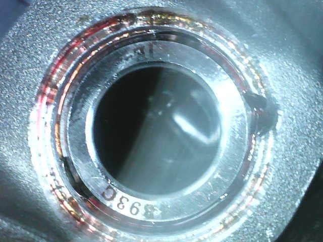
This part did make me a little nervous, but I had practiced enough to get the feel of inserting those clips correctly and so felt confident about it. I did not take any pictures attaching the clips, but I did use my endoscope to verify proper insertion.
First clip successfully inserted.
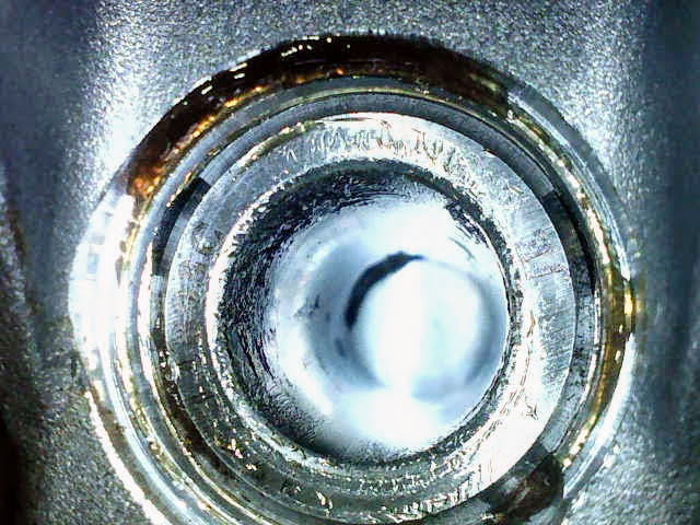
2 for 2
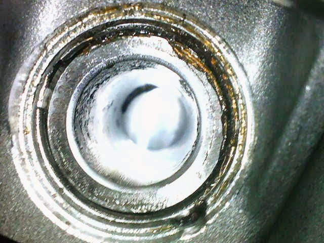
The last one was a piece of cake
I was really paranoid about this part and I found the photos difficult to verify. So I used the endoscope to take video to make sure those clips were in right. https://www.youtube.com/watch?v=tbtR...ature=youtu.be
I did this for all three but am only posting one here.
Next step was to install the IMS Solution. I made two mistakes here that I had to correct. First one was I had slightly mis-aligned the slot with the hole where the oil feed goes. I had to drill out the hole a little to accommodate the nut. Second mistake (easily fixed), I noticed right after I took this photo. There is an elbow that goes on the oil adapter so the line does not feed directly onto it like in the photo. The elbow comes off at 90 degrees and tilted up so that the oil line fits more naturally.
Turned the assembly upside down and installed the oil sumps back in the crankcase.
This is the next special tool I created for dealing with the pulley bolt. I actually created this when I was removing it. Simple piece of 3/4 plywood and a four ft 2x4 attached with five 2" screws. The 2x4 sits on the ground and use a 5/16" bolt in the 3 holes. I measured and located the three holes to align with the holes in the pulley (use your high school bisecting skills with a protractor to get the holes exact). This worked really well and was much better than buying a $225 tool that would not get much use. The pulley bolt is a one-time stretch bolt, so you will need a new one for assembly.
I taped up all the holes to keep out any stray dirt, dust, etc.
You may have noticed the 6mm sheet of plastic which I called my 'Car O.R'. I hung fit from the ceiling to floor and split my 2-car garage in two so I could use the other side. This side stayed closed for the entire 3 months. I mounted an air cleaner off ebay (like this one) to the ceiling and ran it 24x7 to ensure my work area was dust free.
Re-attaching the other parts and its starting to look like an engine again! I actually spent a lot of time figuring out how to assemble the chain guides inside the crankcase correctly. I had missed taking photos of those during the dis-assembly, and it is not well-documented how those parts are assembled. For the 3.6L engine the parts are not symmetrical, and it is not obvious (at least was not to me) how they fit.
Next up was attaching those shiny new cylinder heads.
I did not take a photo of this, but the head gasket is installed between this and the crankcase. Don't forget to install the dowel pins in the crankcase first (like I did).
More ARP bolts and nice diagram with torque specs and tightening sequence. Took a while applying the ARP grease to the bolt threads, washers, and underside of the bolts.
Tightened in two equal steps of 30 and then 60 ft lbs. This is a photo of the mis-sized gasket that came with my gasket kit. When I got to this point I had to wait another week for the right gaskets to come in.
Starting to look more like an engine. I got tired of fishing that chain out of the engine and used a rubber band and an old wrist pin to keep it from going back down into the block.
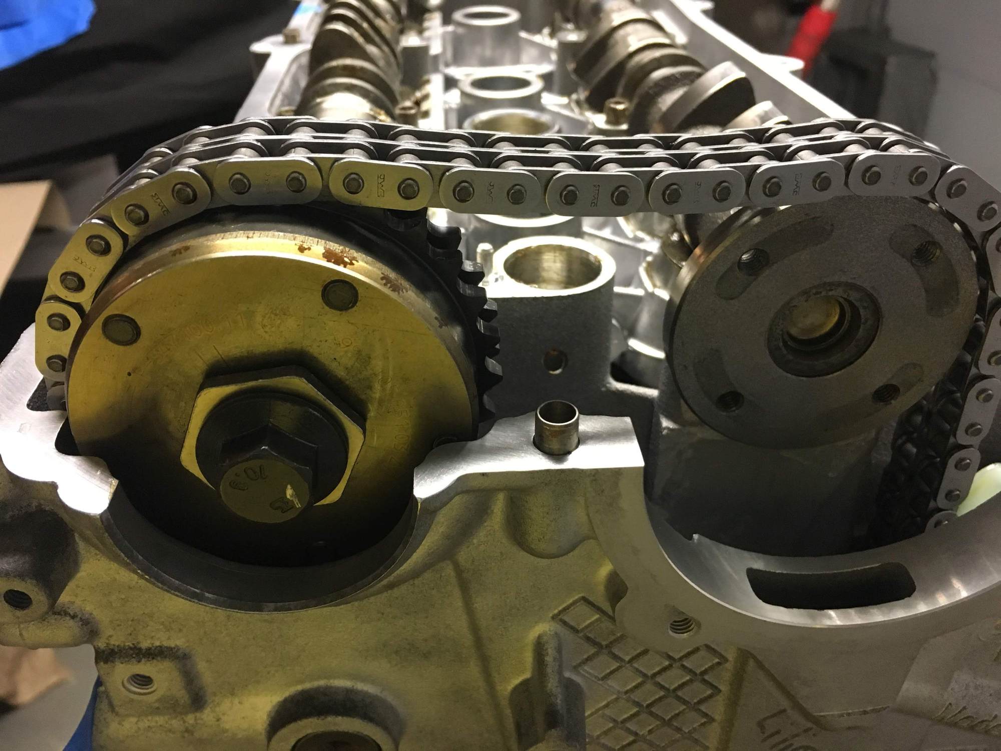
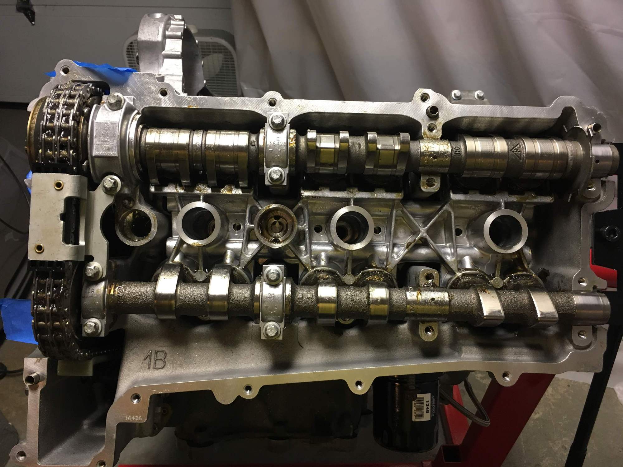
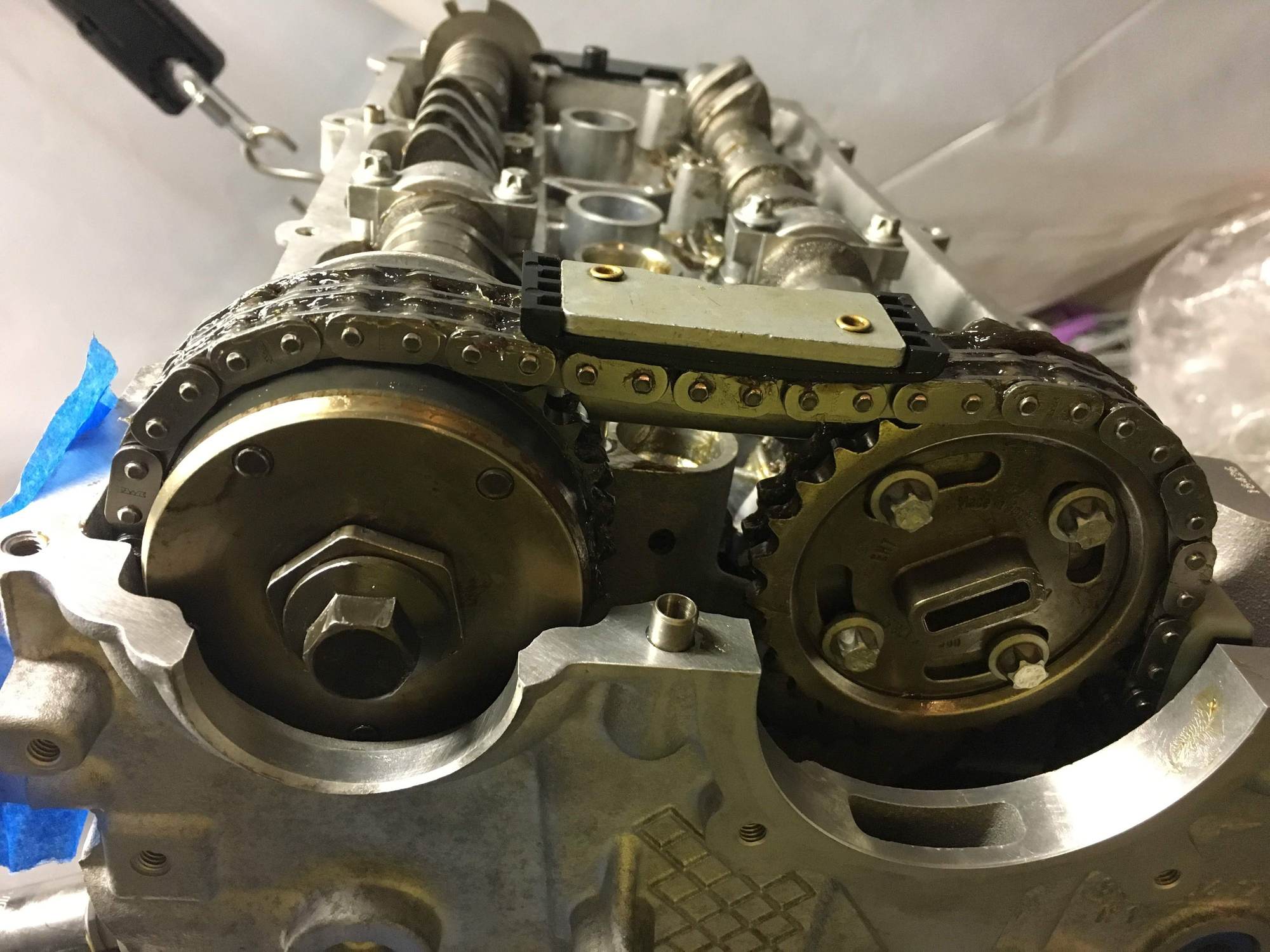
Time to assemble the cams and set the timing. This procedure is different for the 3.4 and 3.6 engines, and is pretty well documented in the Bentley manual. Start by locking the pulley at Cylinder 1 TDC.
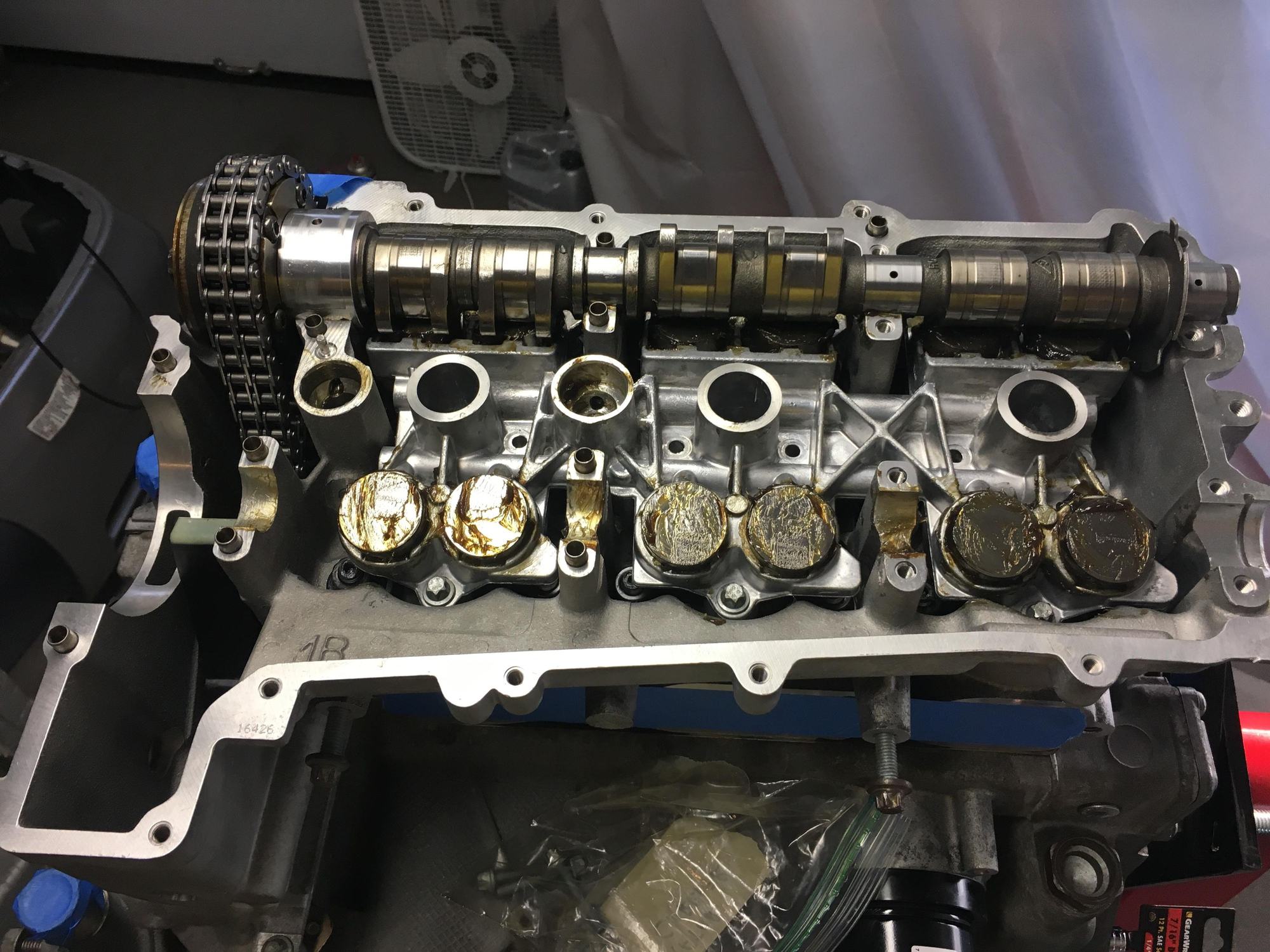
Input camshaft placed under chain with cam lobes near chain pointing inward (456 side). Notice how all cam lobes sit flat across all 6 lifters. The other one will do the same, the cam lobes near the chain also point inwards. Yep, I got to do this all over again after realizing that I missed the bolts in the middle of the lifter carrier.
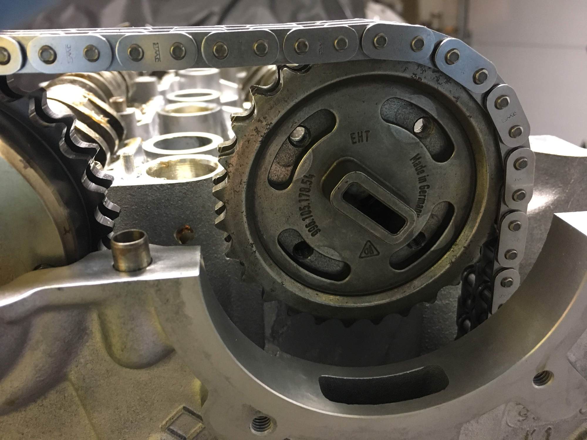
To get the second cam in, remove the sprocket and place the cam under the chain. Again, make sure the cam lobes near the chain point toward the inside. Now you can fit the sprocket onto the cam and on the chain. Attach the bolts finger tight to the sprocket.
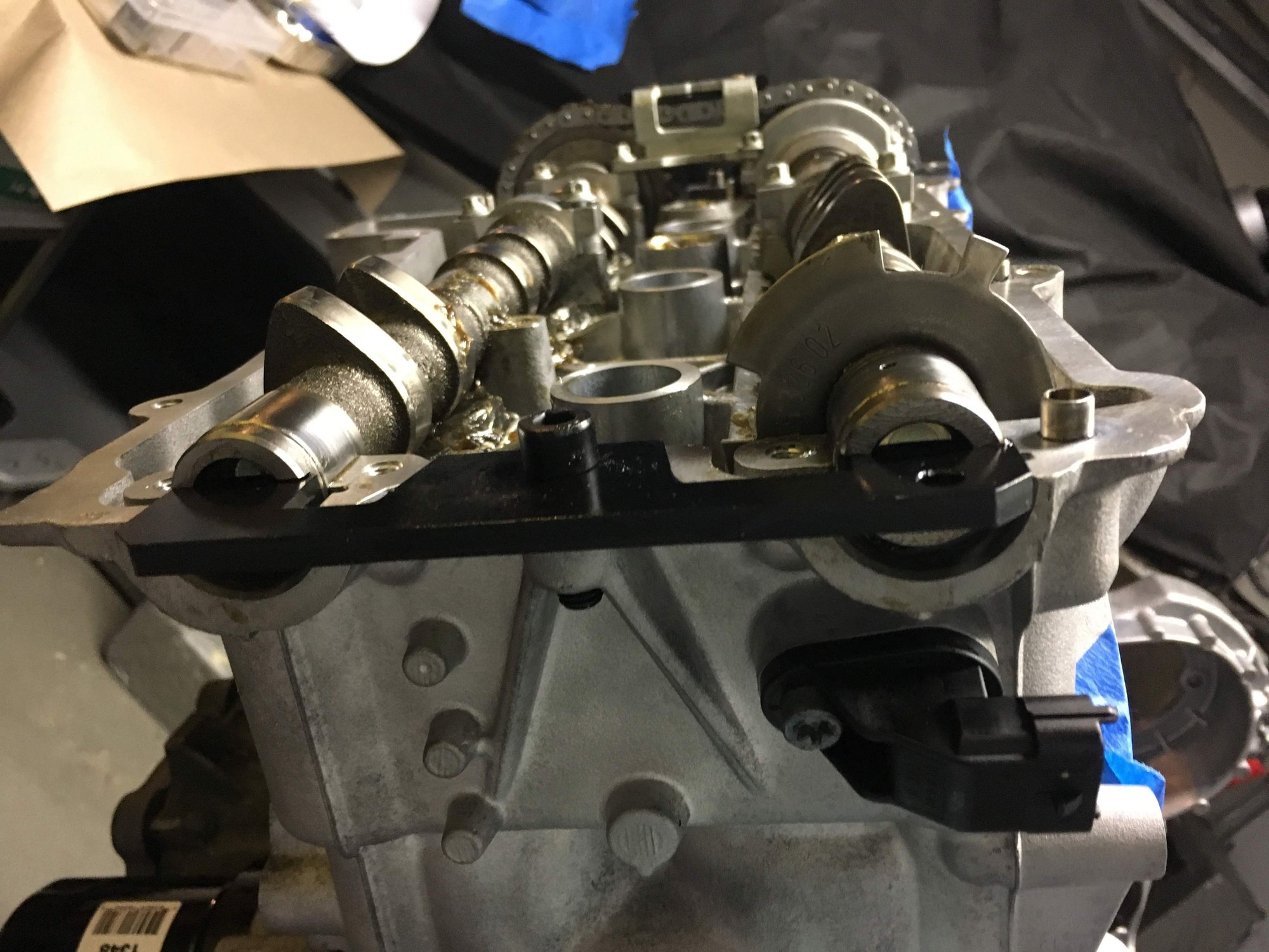
Align cam slots horizontally and attach the cam clamping tool. Nut in the middle only needs to be finger tight.
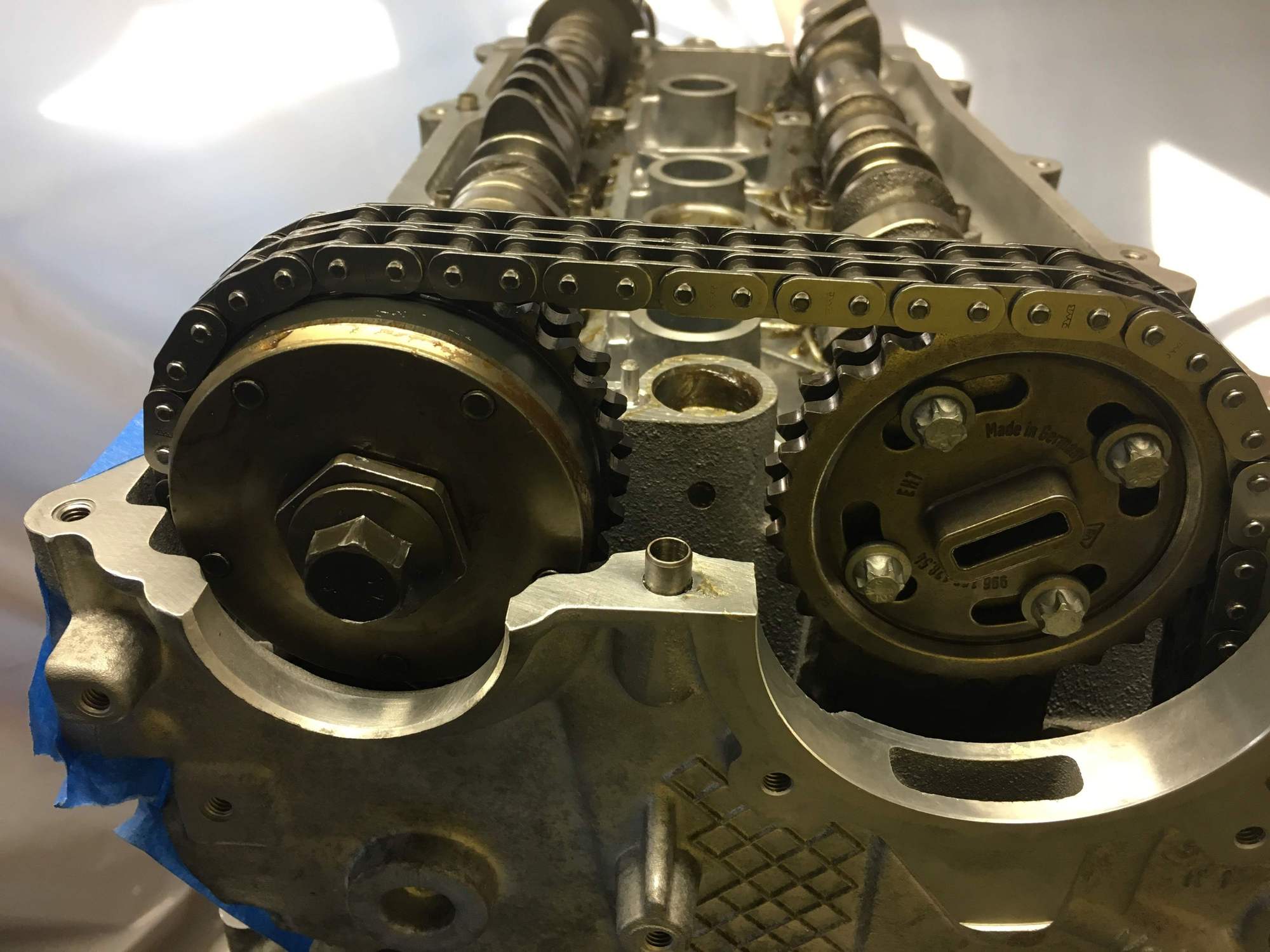
Next attach the cam bearing clamps, finger tight on the screws. See here the orientation of the cam lobes near the chain that are pointing towards each other. When you do the 123 side its the cam lobes on the end AWAY from the chain, and they face outwards. Also note the screws I missed in the middle of the bearing carrier. It may have been Ok to add those at this point but I took it apart and re-did the whole process anyways. Only took about 10 mins.
For the camshaft caps, E = Eintake (Intake) and A = Auspuf (Output/Exhaust). 1 is on the chain and 2 is in the middle.
After the bearing caps are in, attach the chain guide bolts finger tight, then tighten the bearing caps and finally tighten the guide bolts. Then tighten the sprocket bolts and remove the cam clamping tool.
Next step is to insert the chain tensioner back in.
I didn't take a photo of this but the last step is to use the special tool (you need the actual one here - tool 9685, which you can find on eBay) that slides over the nut on the above left camshaft, and sits in the cutout on the right. It has a hole on the left side that holds the cam (thin hex bolt) and lets you torque that nut to 37 ft lb plus 110 deg.
Timing is done.
The 123 side is the same, the only difference is that the camshaft lobes AWAY from the chain point outward. (For 456 they are the lobes NEAR the chain). Again, those cams will fit perfectly flat across all six lifters when aligned properly.
I was still waiting for those gaskets to come in so I did the oil pan cover next. Thin line of drei bond and follow the tightening sequence. Those are a lot of bolts to tighten down in that 5 minute period so get everything ready before hand.
Another belly shot. You can now see the corrected oil line and barely make out the elbow (blue aluminum) going to the spin on adapter.
Also forgot to mention that I did upgrade the hex billet oil drive bit in the oil pump when I re-assembled that. This was from LNE and I thought it was cheap insurance from that drive bit ever having an issue.
Spark plug gaskets came in, so finally putting the cam head covers on. More drei bond application. Careful to not apply too thick a bead, you don't want 'gasket seepage' into the crankcase, which could break off little pieces of gasket and might clog up oil galleys.
Take note of orientation of the scavenge oil pumps on each side. There is a slot in the pump that aligns with the slot in the cylinder head. The other side I was able to dis-assemble and re-assemble after cleaning, but this side is new because I broke a screw while taking it apart. I probably didn't need to dis-assemble it but it gave me something to do while waiting for all my parts to come back in.
For this I could have assembled another special tool as others have done, but I've read a few posts about bad RMS installs and so I asked LNE if they had an install tool. I don't think it's something they do as normal course but they were awesome and offered to rent me the tool. It was well worth it and made the job really easy.
Started by cleaning those surfaces again with acetone. The RMS has a PFTE surface so you don't want any grease or oil.
Lay the tool down on top of the seal, leaving the plastic inner ring in place.
You can see how the ring fits nicely onto the tool.
Snug the ring up and seat it in the tool.
Place it onto the crankshaft.
Thread the middle bolt finger tight.
Attach the housing, and finger tighten the screws.
Slowly tighten the center bolt to draw it into the engine. You will feel a definite stop when it is done, does not need a lot of force. Don't remove it right away, leave it in place for 2 hours so the gasket can seat properly. Then remove it.
This is a super-high quality tool and made this job really easy and foolproof. I'm glad I was able to use it and also glad that I did not have to buy it, I think it goes for over $600.
^Oh yea, that's how I did it too. No worries about the weight. I was just curious if LN has changed the design of the pistons. Yours is definitely ~7g lighter than mine. My stock rods are within 0.6g of each other from the factory so it's pretty good but of course the more important part is balancing between the reciprocating mass and rotational mass.
We continuous improve our designs as we get access to older parts that have been returned to us for freshening up. Likewise, new forgings and machining processes become available to us and we take advantage of them.
In fact we are testing two new piston designs now.
Great thread! We're working to make rebuilding the M96 engine more DIY-friendly like offering more tool rentals and help through our new support ticketing system. We can't teach you how to build an engine, but threads like this help to show that with the right guidance and training, like classes from The Knowledge Gruppe, you don't need to be afraid of the M96 engine, and they can be built right without bankrupting you.
We continuous improve our designs as we get access to older parts that have been returned to us for freshening up. Likewise, new forgings and machining processes become available to us and we take advantage of them.
In fact we are testing two new piston designs now.
Thanks Charles for the info amd that makes sense.
Btw, I've put 8k miles on my LN 3.8 with IMSS now. It's running smooth and strong with no issues whatsoever.

 09-05-2018 | 07:54 PM