When you click on links to various merchants on this site and make a purchase, this can result in this site earning a commission. Affiliate programs and affiliations include, but are not limited to, the eBay Partner Network.
After torquing I gripped the crankshaft at the flywheel side and rotated it to see how it felt. It rotated smooth as silk, felt like it was being held by warm butter.
Important note!
I forgot to mention a rather important step above - mounting the thrust bearings in the bottom carrier. I did not take a photo of these, but they must be installed with the depressions facing outward. The mount right in the middle of the carrier on either side of the center journal. Again, add assembly grease before placing the crankshaft onto the carrier.
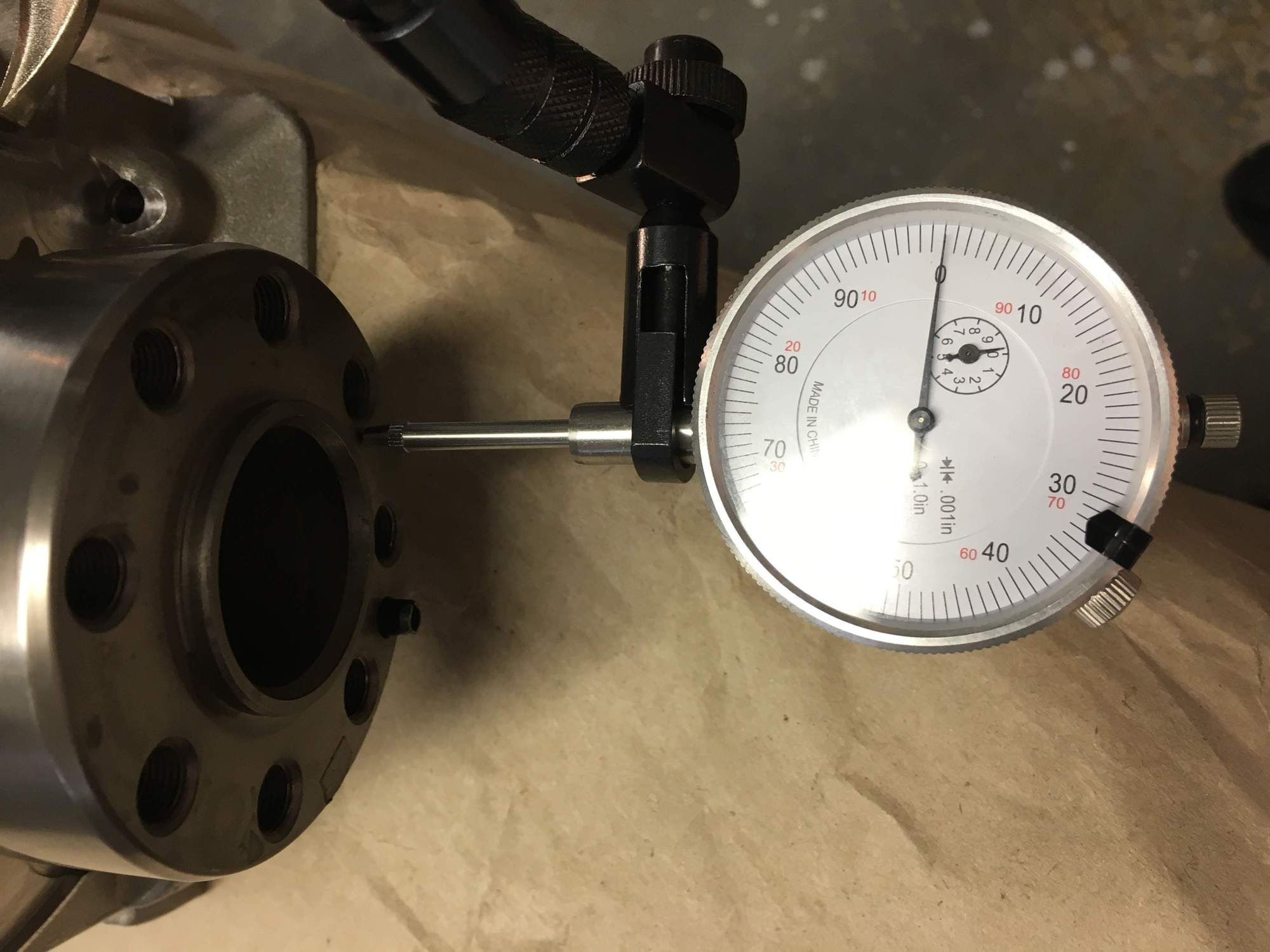
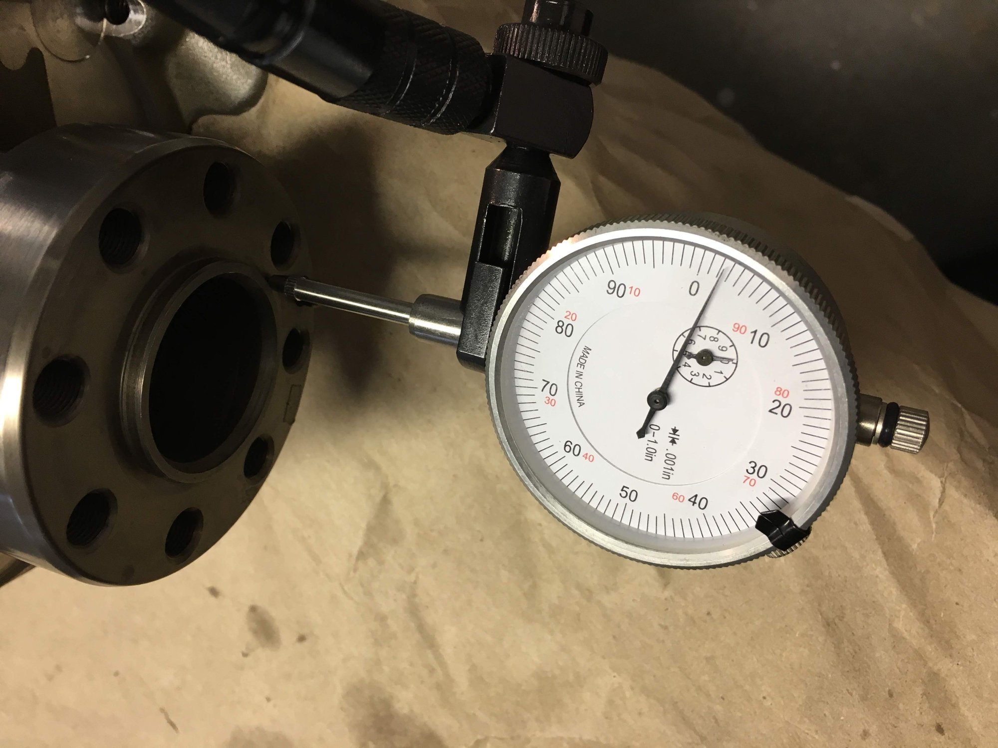
Next step is to check the axial free play.
Axial free play measurement. Push the crankshaft inward (here to the left), and then zero out the dial. Now push (pull) the crankshaft outwards and measure the free play. .0023in = .058mm.
According to workshop manual:
Crankshaft Endplay
New Installation 0.05-0.24 mm
Wear Limit 0.28 mm
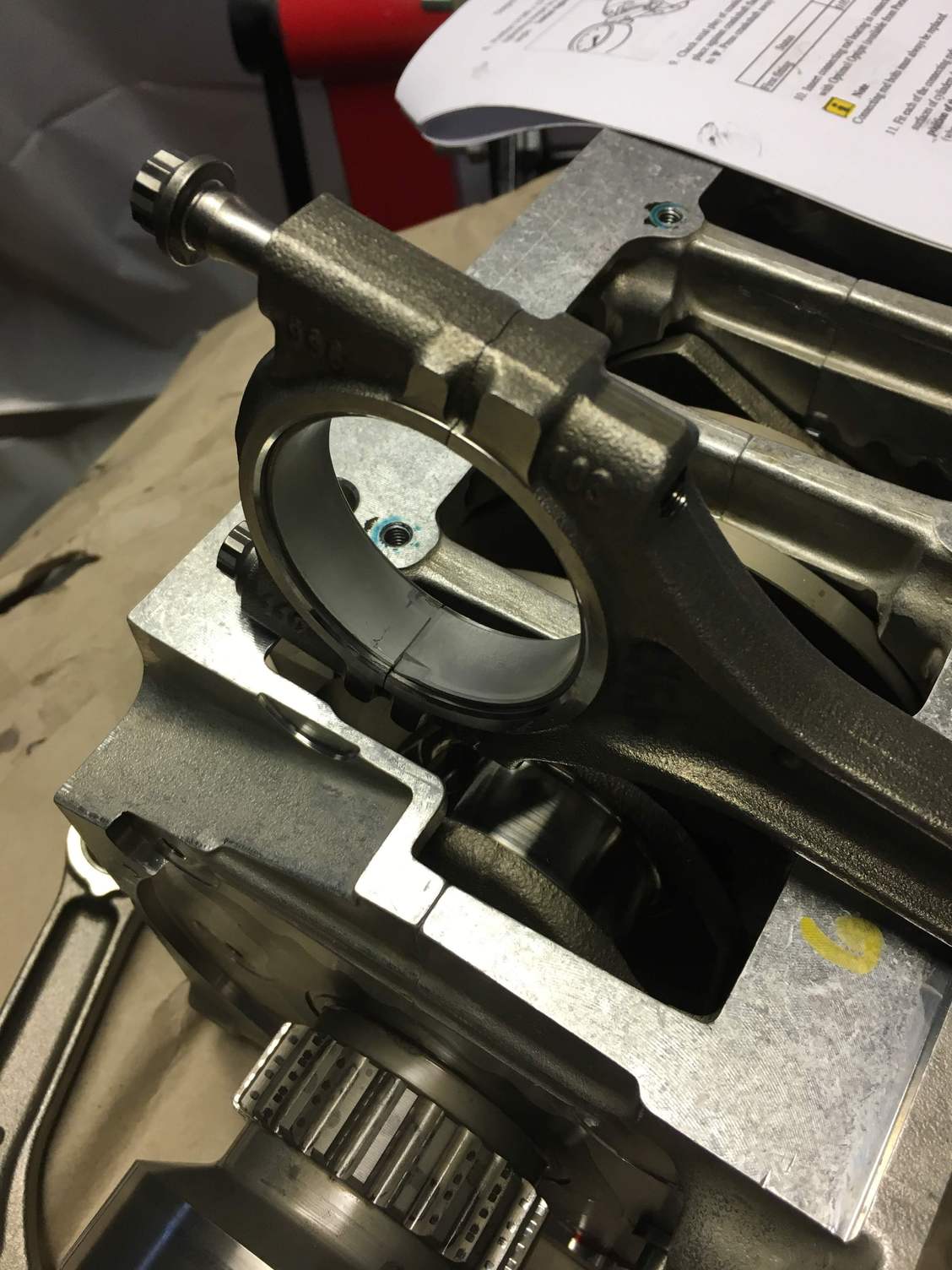
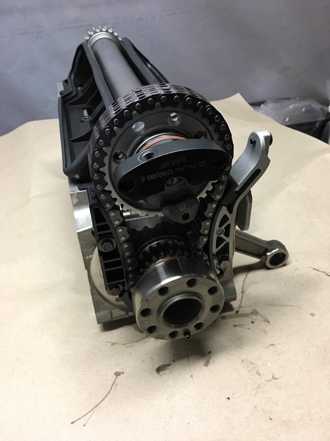
Next step was to attach the 4,5,6 piston rods to the crankshaft / carrier assembly, along with the IMS shaft. Again, ARP bolts used for the piston rods and remember to keep the bearing slots aligned towards the bottom.
Remember to orient the piston rods in the right direction when attaching to the crankshaft. ARP bolts used again, greased and torqued to the right specs. Note that in this picture the bottom is actually currently facing to the back, so the bearing keys need to be facing up also (reverse of how it is showing in the photo).
Rods attached and torqued, IMS shaft attached with new chain, guide and tensioner. Again, here you can see the 456 rods on the crank. The assembly is upside down, so the journal keys should be oriented up, towards the IMS shaft.
This engine already had an IMS solution in place. I sent it back with my crankcase to LNE to have it refurbed and re-pinned.
Hi Coopduc. This was a rebuild of an M96/03 3.6L engine to a 3.8 LNE. I pulled together specs from a variety of places:
1. Bentley Workshop Manual
2. eBay DVD for Porsche 996 98-04 Workshop Manual
3. Online purchase of 2001-2006 996.2 Service Manual
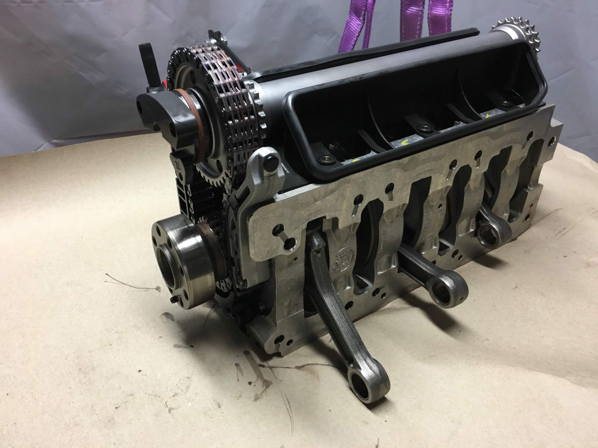
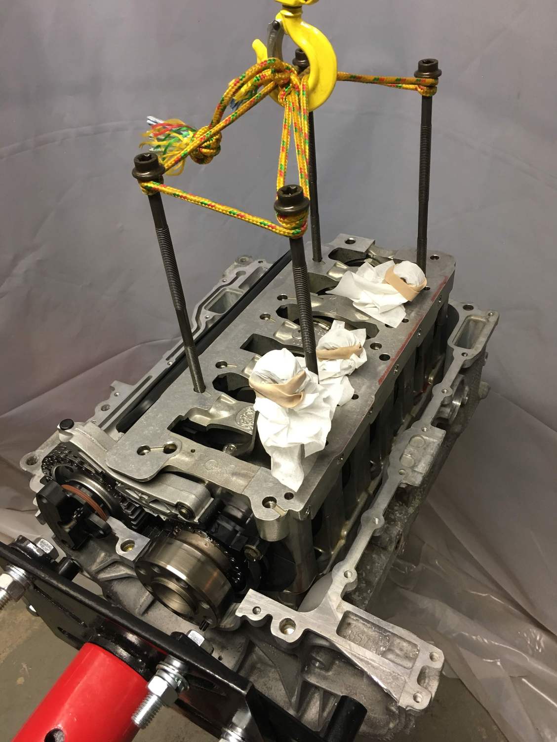
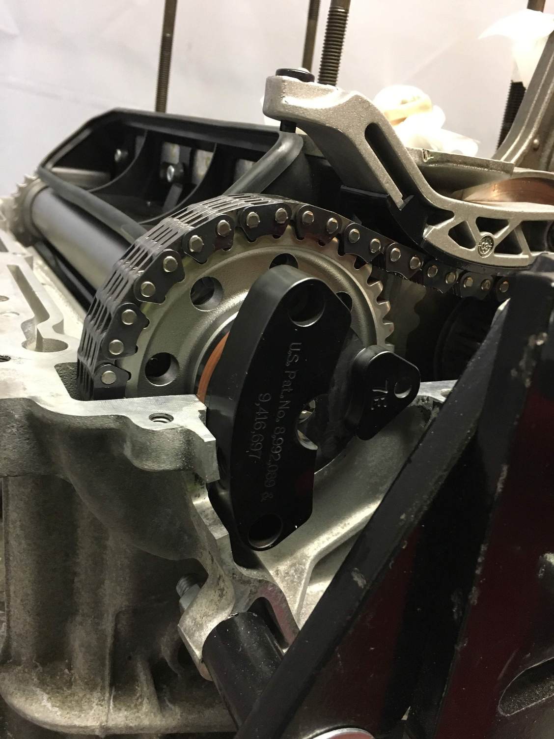
Next step is to place the carrier assembly into the 123 side crankcase. That assembly is heavy so you'll want to use a lift to carefully lower it down. I of course did not have the Porsche special mounting tool, so I improvised, which worked great: Saved my head bolts from the teardown with some rope and used them to mount my special carrier tool.
The carrier now sitting in the crankcase. Make sure to rotated and line up that IMS properly with the hole for the oil feed.
Now that it is secured, you can turn it back facing up and insert the 1,2,3 pistons. Definitely want to use a tapered ring compressor for these, lube it up with assembly grease and the pistons slide right in (put some grease inside the cylinder also). I had already purchased one previously, but I also got one back along with my crank halves and other parts from LNE. Don't bother with one of the cheap band-style ones, you will waste your time and maybe even damage something. And don't forget to first clean the cylinder walls again with Kim Wipes and acetone.
Used a torque angle gauge on the piston rod bolts, again using ARP grease and tightened up to the proper specs. You can also see the pulley is mounted here finger tight so that I could rotate the crank while inserting the pistons and positioning them for tightening.
I skipped some photos here of mating the top and bottom crank halves. This is the part where you have to apply a thin bead of Drei bond and then get it all together within 5 minutes. I got some help here because you have to make sure the chain come up through the top half, and the piston rods (sans pistons) fit up into the top crankcase. Note the KimWipes and rubber bands I used earlier to protect the cylinder walls for this step. Also make sure to lay everything out first, set your torque gauge, and open to the page showing the bolt tightening sequence (or memorize it). 5 minutes is actually a long time, but it seems like you are going to run out of time when you get to this step.
Nice pics. It's interesting your pistons are so much lighter than mine. Mine are ~401g each. Do you know how much your wrist pins weigh? Mine are ~89g each.
Hi Ahsai. I unfortunately did not think to weigh my wrist pins. I do recall holding both the old and the new and not feeling a significant difference though. The balancer did note that he was very impressed with the balance of the crankshaft as well as the consistency of the rod weights. They were within 1g of each other from the factory. He got them down to .1 gram.
Next step is to install the shaft sealing gasket. I used the 'special tool' that I found on this thread (I think from Ahsai - thanks!). Home depot 1 1/2" cap and a washer. Then use the pulley bolt to draw on the gasket. Don't use any oil or grease, and make sure to clean the engine surface with acetone again first. Also make sure no gasket material (drei bond) is in there.
^Oh yea, that's how I did it too. No worries about the weight. I was just curious if LN has changed the design of the pistons. Yours is definitely ~7g lighter than mine. My stock rods are within 0.6g of each other from the factory so it's pretty good but of course the more important part is balancing between the reciprocating mass and rotational mass.
Time for the scary part, assembling the 4,5,6 pistons and attaching the wrist pins. I suggest doing a bit of practice first on the bench. The tool I had was a bit of a disappointment because the plastic wrist pin insertion rod did not fit. It was too big. However, it's not too difficult to get the wrist pin in there, you just have to work with it a bit. Tools I used for this. Note the endoscope I bought originally to verify the scoring that caused me to take on this crazy project.
This is the wrist pin insertion rod. I had a hard time reading the markers on the pulley and used an erasable marker to number them.
You can see it extending into the cylinder. You should be able to use this to insert it through the piston and into the rod as shown here. That lets you line them up for inserting the wrist pin. However, this rod does not fit into the piston. With some finagling I managed to get them to line up and get the wrist pins in.

 09-04-2018, 11:28 PM