When you click on links to various merchants on this site and make a purchase, this can result in this site earning a commission. Affiliate programs and affiliations include, but are not limited to, the eBay Partner Network.
Don't quote me on this, but I think 2012 or 2013 might have been the first year with different pin offsets that are bank specific - I think it was whatever year Porsche stopped using the VW 6 cylinder and came out with their own 6 cyl for the Panamera and Cayenne. I can't find my notes and the sample pistons I purchased from Porsche to see what differences they made from model to model are squirreled away somewhere I can't find them.
I think the 9A1 piston has a .060" offset- again, those samples are hidden away somewhere.
It took much longer than I hoped, partly due to me being busy, and also because of a huge stupid mistake (more on that later), but I finally got my car back together and on the road this weekend. It runs unbelievably smooth and strong and I couldn't be happier with the result.
Here is the first batch of updates detailing the assembly process.
Head work
The first thing to come back from being sent out were the heads, done by Len Hoffman of Hoffman Automotive. He did a fantastic job, pressure testing, new valves, guides, springs. I opted to have stage I port work done also. I can't believe how clean the heads came back - they look brand spanking new.
Heads look amazing! Work done by Len Hoffman from Hoffman Automotive.
The head took about 7 weeks to come back. The next step was to balance out the rotating assembly and I was hoping I could same some time and do it while waiting for the crankcase to come back from LNE.
However I realized that the pistons, wrist pins, etc. were also needed and those would not get back to me until the crankcase was completed. So the hardest part of all this was the waiting for those parts to come back.
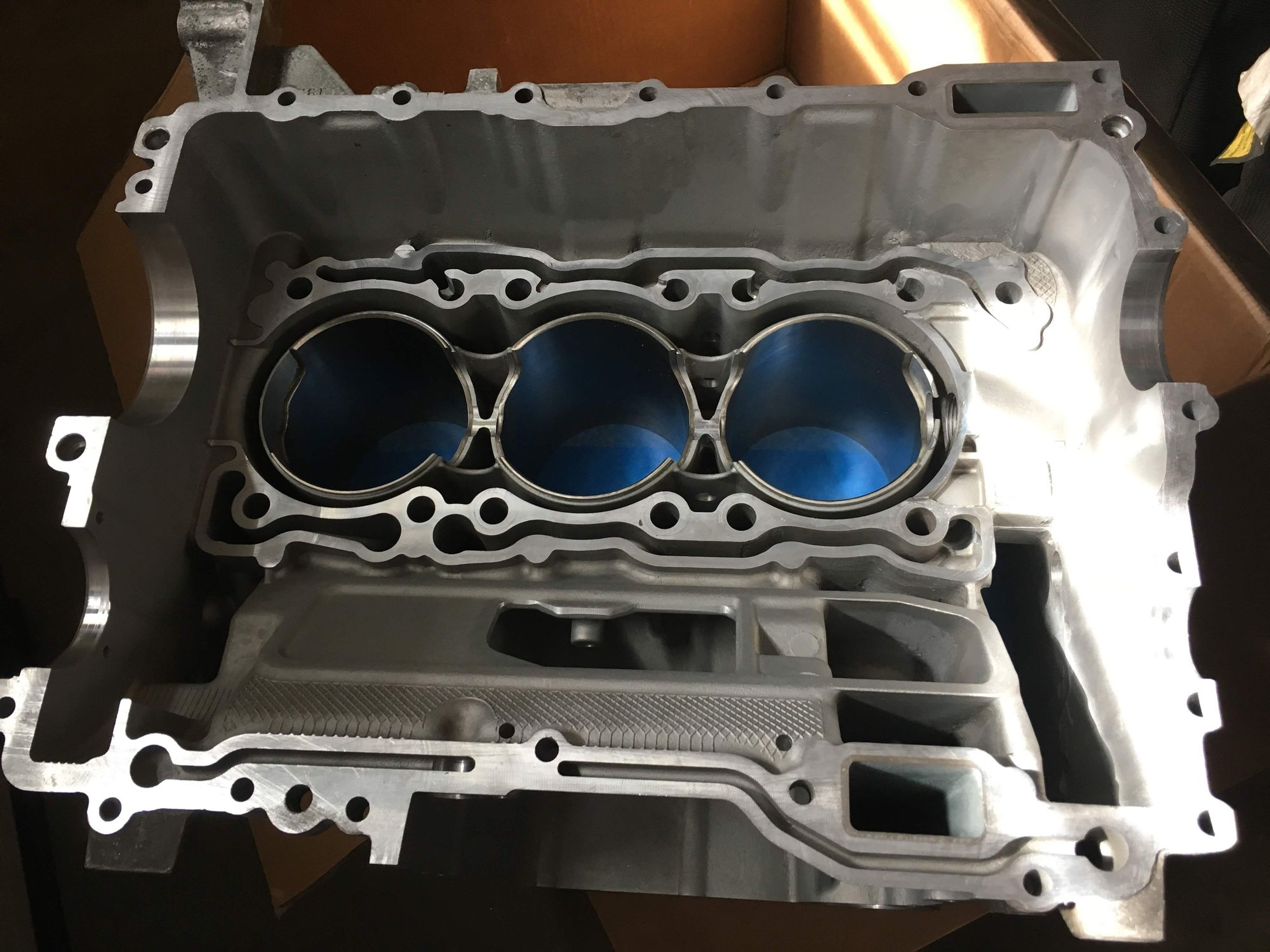
Crankcase halves with new LNE nickie sleeves
The crankcase took about 8 weeks to get back to me. I was dying waiting for it all to get back, but I was very happy with the result. LNE does some awesome work and their service was awesome.
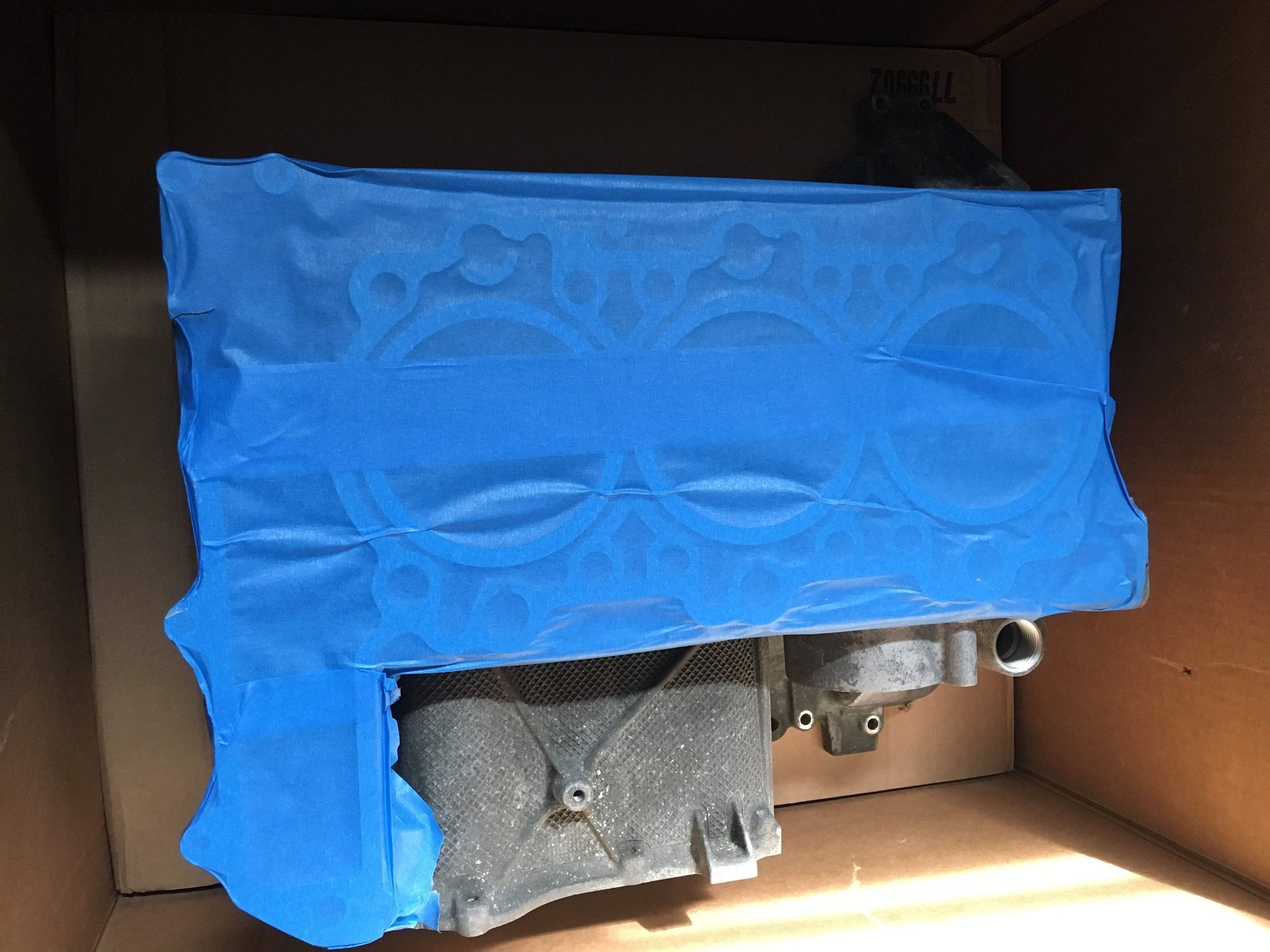
Big box arrives with crankcase
Wow, that looks nice.
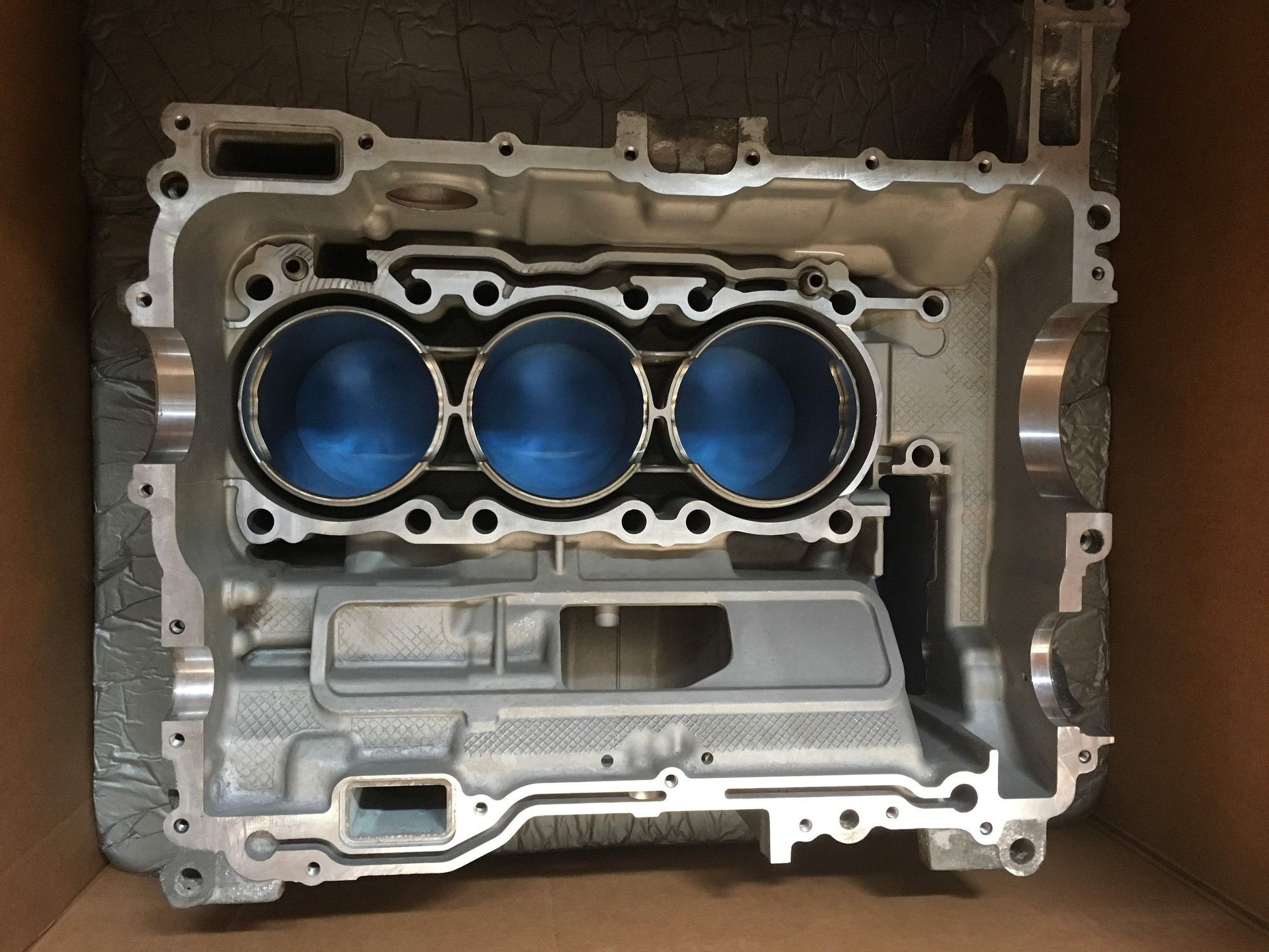
The other side.
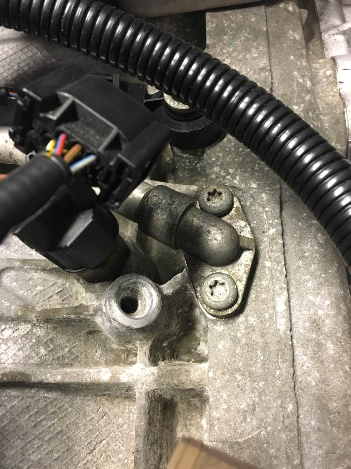
One thing to note if you send out your crank like I did to LNE is to remove ALL parts from the crankcases. I removed everything EXCEPT the spacer sleeve (pic below) used to hold the AC compressor, as I thought it was pressed in and did not come out. When I got to that part of the assembly I realized I did not have that part and was stuck. Fortunately LNE was accommodating and sent me one that they had in their shop.
AC Compressor sleeve on crank that I forgot to remove, and discovered only when I got to that part of the assembly.
Now that all my parts were back it was time to send out the rotating assembly for balancing. As mentioned, this had to be done serially (after I got all the parts back), so I was in for another two week wait. I sent the parts to Performance Automotive Technology which is local to me. This guy did an awesome job. He is really meticulous and I has some good discussions with him about engine rebuilding and some of the unbelievably accurate machinery he has. He also has some really cool projects going on that he showed to me.
Next step is to gap the rings. I first put the crankcase halves and all parts into my upstairs playroom which has a nice temp control (crank cases are 45lbs each, so carrying them up to the third floor was good exercise).
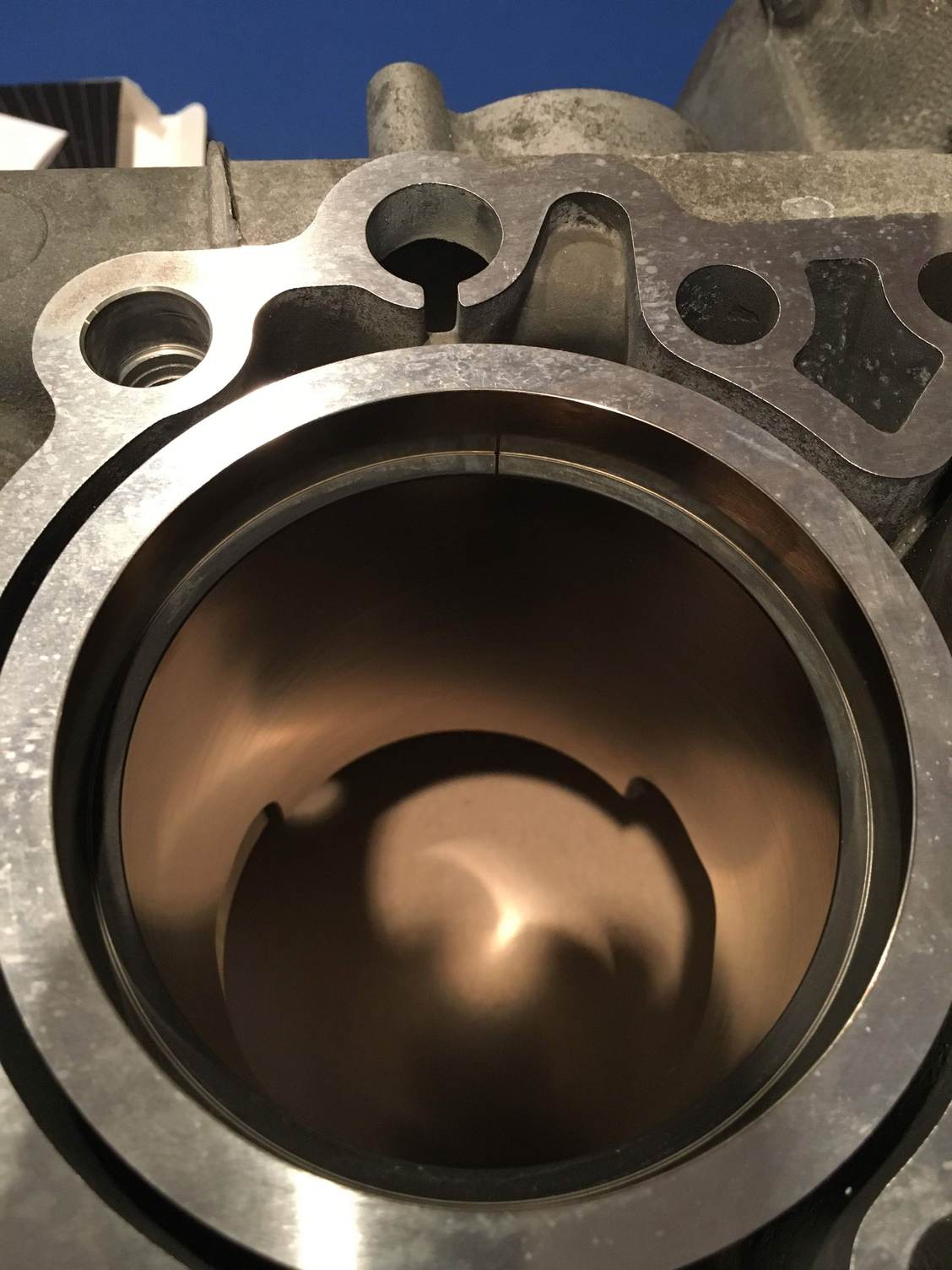
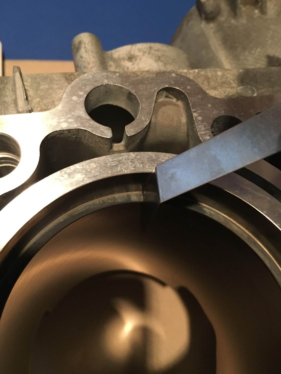
Cylinder halves placed into a room set at 72 degrees. Will come back tomorrow and do the ring gapping.
Before I checked the gap for each ring, I carefully inspected the ends of each ring for any burrs some magnifying glasses. I was amazed at the consistency and quality of the rings - there was not a single burr found.
Ring square used to position ring in the cylinder for measurement.
Ring square removed.
Gap was measured at 0.020
All the ring gaps came in above the minimum of 0.015, and they were consistently around 0.020 thousandths. I could not believe this at first and had to go back and re-measure them twice. They all came out within .001 of each other. This was the case for both the compression and the oil rings. So no ring filing necessary!
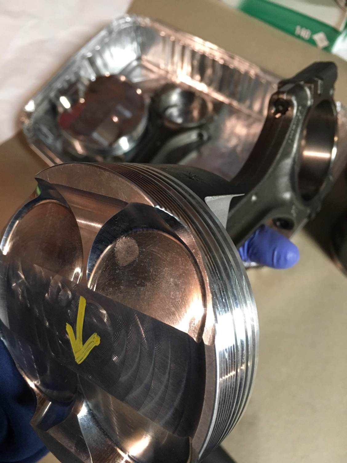
Next step is to pre-assemble the 1,2 and 3 piston assemblies. I wanted to get lots of practice getting those tricky wrist pins in, so I practiced on my old pistons first.
It seems silly, but the hardest part I had was actually getting the clips into the tube and placed correctly. It took me about an hour of frustration before I figured out the easiest way for me to do it quickly and consistently.
Also make note that these clips can un-spring and fly out of that tube very easily and end up anywhere, so do not do this near your engine if it is partially assembled!
1. Grease is crucial - put some assembly grease inside the tube
2. Press the clip into the tube vertically (clip gap pointing straight up) then rotate it horizontally until the entire thing is inside the tube diagonally. Keep the clip gap and tube gap aligned.
3. Use a flat-blade screwdriver to hold the gap side in the tube, and gently pry up the other side until it is horizontal
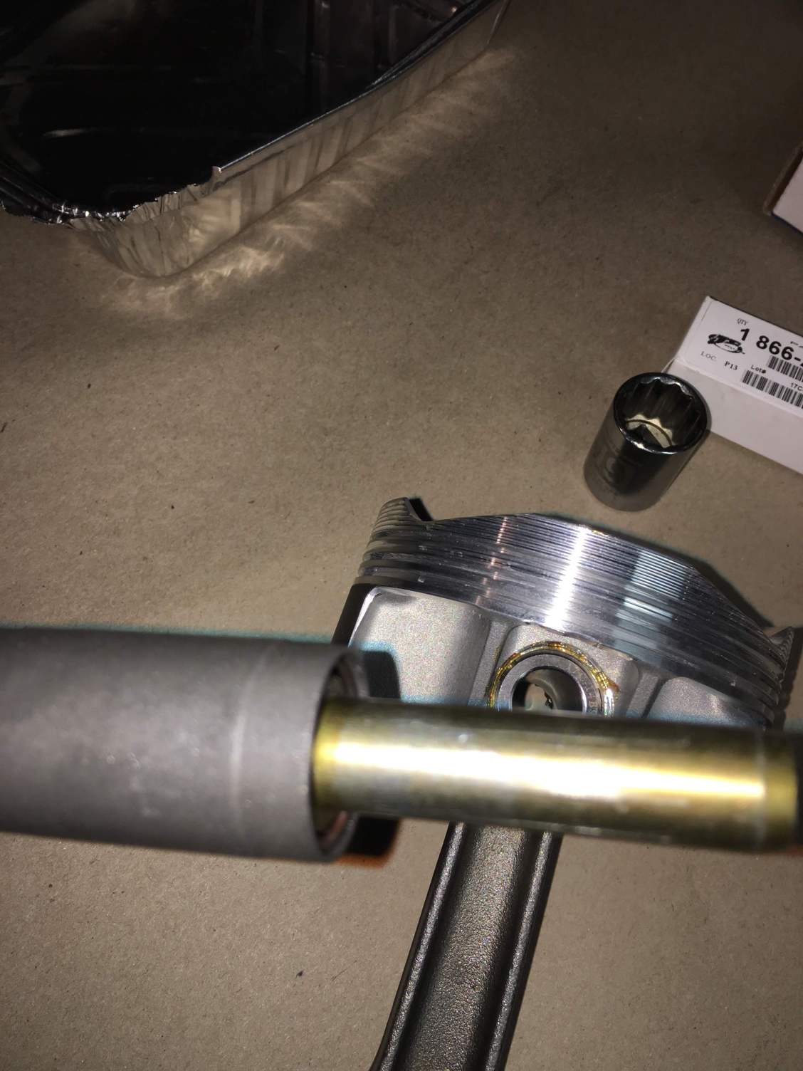
Next step is to place the rod into the tube. Mine has a screwed **** at the end allowing me to adjust the depth that the rod extends past the end of the tube. I did not take a picture of it, but the rod has a small notch at the end which accommodates the wrist clip and fits exactly inside the hole for the piston wrist pin. I adjusted the depth so that it extended just enough to push the clip out of the tube, into the piston hole right up to the depth of the wrist pin.
Wrist clip insertion tool. The other end has a **** allowing me to adjust how far this end will extend beyond the tube, and into the hole where the wrist pin sits.
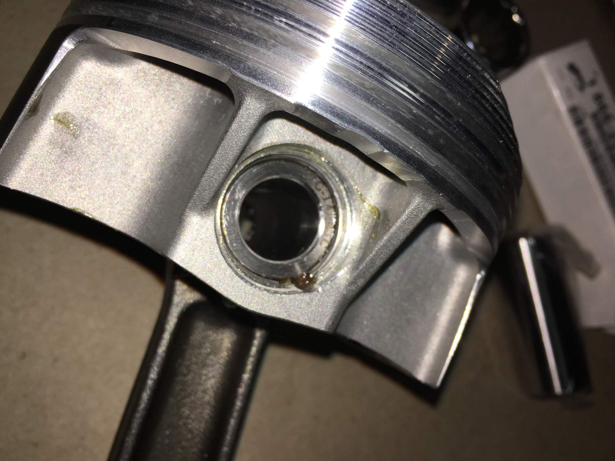
Here you can see the pin inserted correctly into the piston. Looking closely at the hole you can see an outer bevel. The insertion tool fits perfectly into that bevel. Adjusting the **** controls how deep the rod extends beyond, and thus into the hole. I set it so that it will push the clip to the right depth right against the wrist pin and into the notch made for the wrist clip. It's hard to make out in that photo but the clip site perfectly in the notch, right against the wrist pin. I practiced this a few times and with a firm sharp shove on the **** the clip goes right in and sits perfectly.
Don't forget to clean your parts. Again. and. again......and again.
Here is what the rod journals looked like after the first wipe down after coming back from balancing. I had already cleaned them previously in an ultrasonic cleaner.
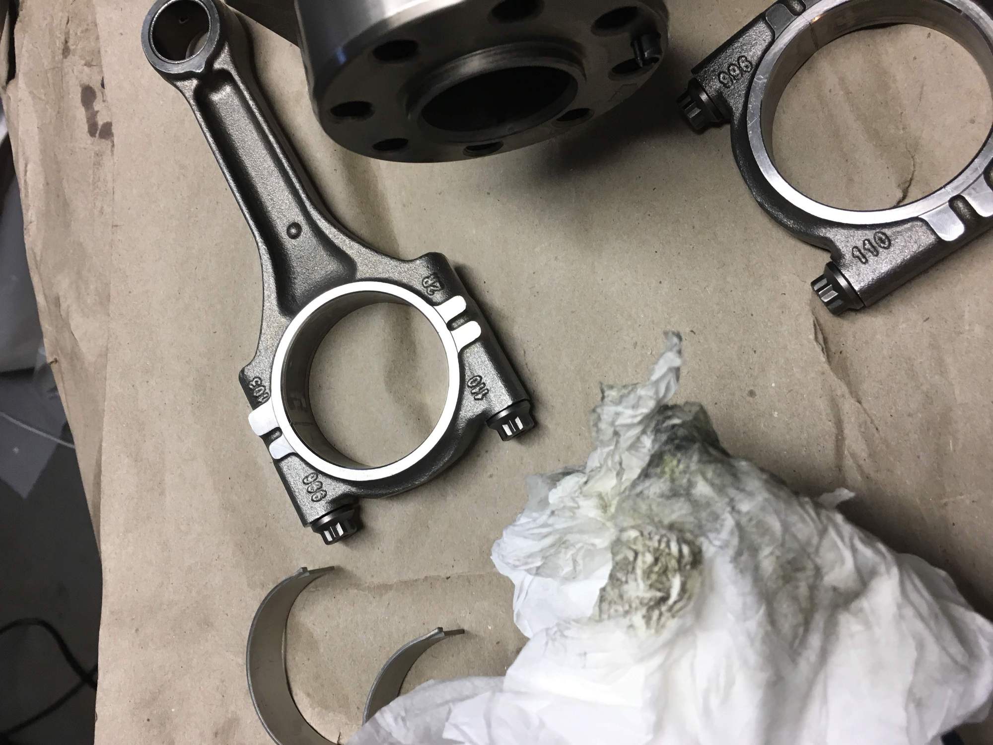
After getting pistons 1,2 and 3 assembled with the rods I placed the bearings into the journals. The shop manual notes that it is important to orient the notches for the journals towards the bottom of the engine, so that they pick up lubrication. After inserting the bearings I drew arrows to point in the down direction to make sure I oriented them correctly later when I put them onto the crankshaft.
Note the notches for the journals. Also note that with these forged cracked rods the two halves only align in one direction, so don't get them mixed up. (Actually not difficult to do because they are not actually flat, and when aligned correctly the two halves fit perfectly)
Arrow drawn to indicate notches on the bottom half.
I forgot to mention earlier that after I did the disassembly I got a 15L ultrasonic cleaner off eBay for cleaning the parts.
That size worked but in retrospect I wish I had gone with the 20L model, which would have been large enough for all the parts (one at a time). For the carrier assembly for example I was able to clean the top and bottom a half at a time. First one end with about 1/4 sticking out, and then the other end with the now clean end sticking out. For cleaner I just used water and Dawn dish detergent, with temp at 45d C. Parts came out super clean! After that I patted then with a shop towel and then used my air compressor to blow out any remaining water.
Next up - assembling the crankcase carrier assembly!
Again cleaned the journals with acetone and Kim Wipes until they came perfectly clean.
Bearing placed in bottom carrier.
Crankshaft aligned for insertion.
Crankshaft placed into bottom carrier. I did not take a photo because my hands were greasy, but don't forget to put lots of assembly grease on those bearings before placing the crankshaft.
More grease applied and top half placed.
End shot of two halves.
I used ARP bolts for the carrier halves. They came with a neat diagram indicating the torquing sequence, and instructions on how to properly lubricate and torque them. Adding the ARP grease to the threads and underside of the bolt heads before assembling.
Torqued the bolts according to the sequence, in three parts. 17, then 34 ft lbs initial. Then final torque to 50 ft lbs.

 07-08-2018, 04:37 PM