When you click on links to various merchants on this site and make a purchase, this can result in this site earning a commission. Affiliate programs and affiliations include, but are not limited to, the eBay Partner Network.
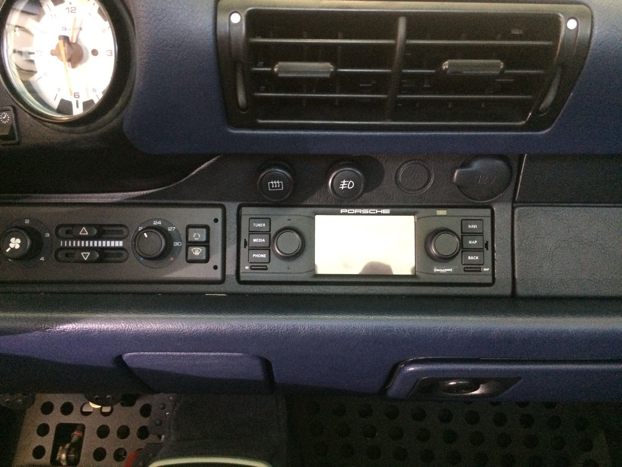
I've read many of the threads and learning from each have made the following upgrade to the HiFi speaker system in my 1996 Targa. This post is just for upgrading the speakers -- doors and rear parcel shelf. As an side note, I replaced the aftermarket head unit installed by the PO (that installation ruined the original wiring unfortunately which I repaired back to factory) with the Porsche Classic Radio (expensive but highly recommended) and bypassed the Nokia amplifier (left in place for now) using the custom audio bypass cable from Tore � http://www.bergvillfx.com/index.php/...fi-bypass.html . That installation is for another post, although others have done a great job covering that process so there may not be more that I can add.
NOTE 1: You may need to remove the door cards if you plan to replace the TWEETERS. If you are only replacing the MID and LOW speakers and keeping the original TWEETERS you do not need to remove the door cards.
NOTE 2: Now is the time to replace old screws, washers, etc. related to the door card and HiFi door cover. ( I took the time to replace the door handles with a set of aluminum handles from Rennline.) If your door pocket attachment is broken (or even if not), now is a good time to do the upgrade fix. See this 993 Door Pocket Attachment Reinforcement and make the order. Great install procedure is at post #299 pg.20 (My additional notes are at post #317 pg.22. Simple to do and makes a difference for your elbow.
Now to the process:
HiFi DOOR COVER REMOVAL
1. Open the door pocket cover and remove the screw holding the HiFi door cover at the rear of the grab handle.
2. Remove the 6 screws on the outside of the cover -- 1 at front, 4 along the bottom, and 1 at the rear. The cover should come off easily by pulling from the bottom. There is a metal fitting at the top of the cover to lock into the front of the grab handle.
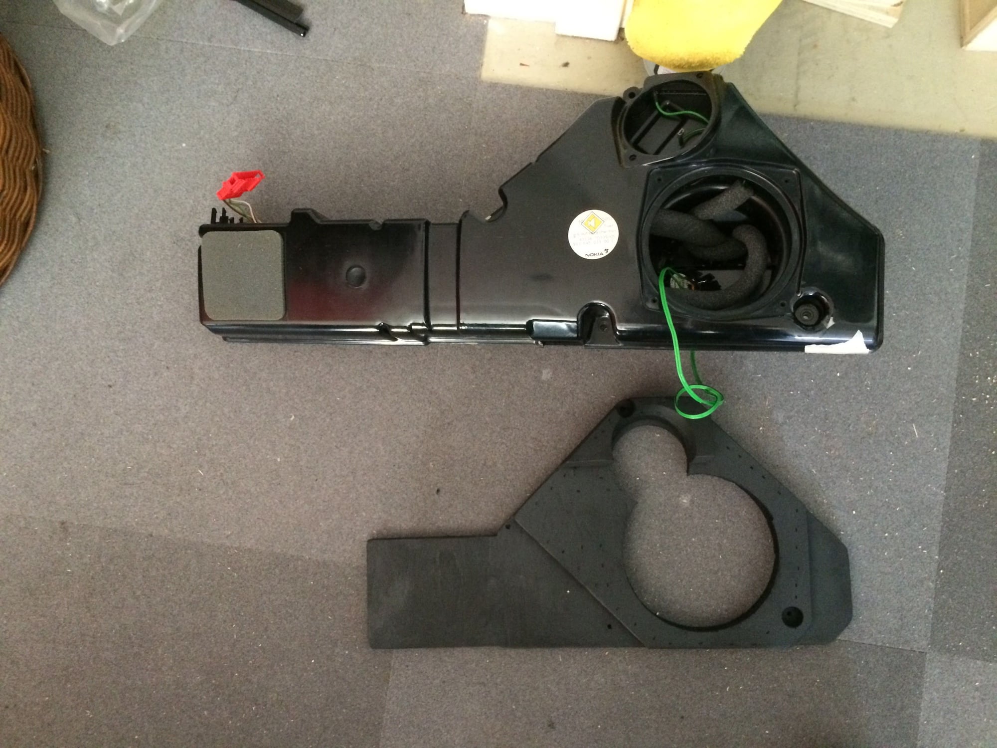
HiFi BOX REMOVAL
1. Remove 4 screws that hold the black box in place.
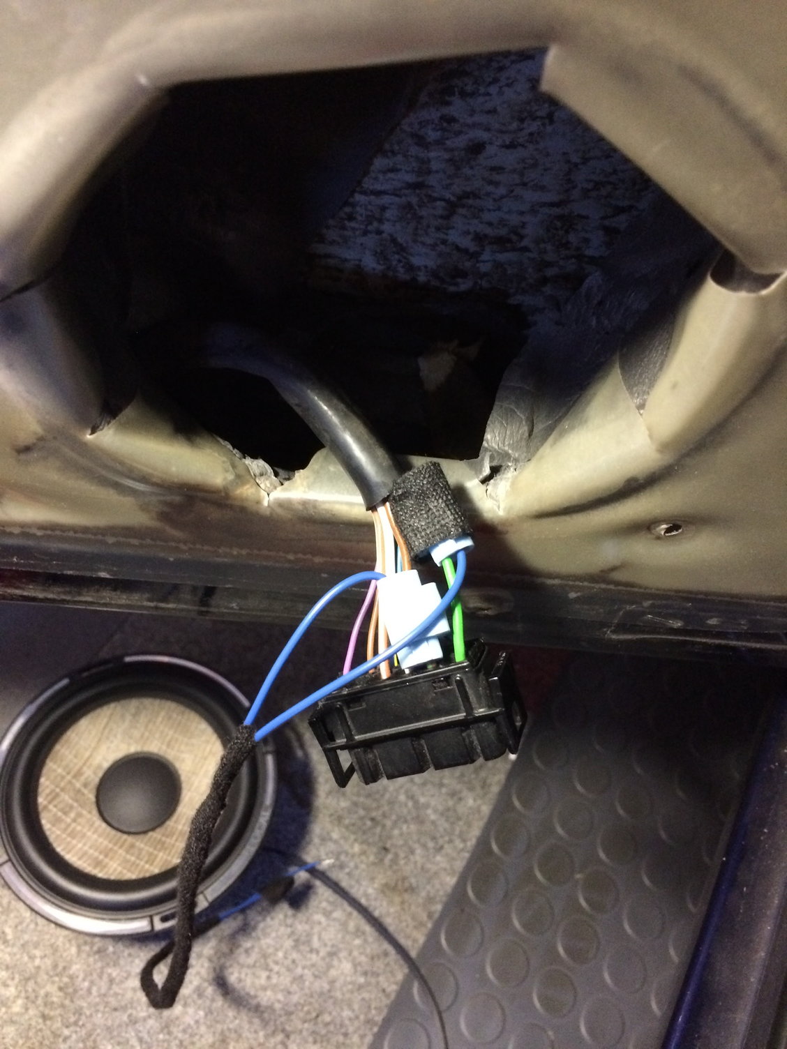
2. Unplug the main wire connector in the rear.
3. Unplug the wire connector for the tweeter.
DOOR CARD REMOVAL (You only need to do this if you are replacing the TWEETERS)
1. Door handle -- slightly pull on the door handle and you will see the metal rod that is connected to it. Use a screwdriver or just your finger to push up on the rod. It should release easily.
2. Door card -- there are several steps here:
2a. There is one screw at the rear of the door pocket cover (the connector) that need to be removed.
2b. There are also two hidden trim plastic buttons on the front leading edge near the window switch that need to be gently pried from the door. Use the right tools to remove them -- I have some plastic interior fitting tools, but a wide blade flat screwdriver can also work if you are careful.
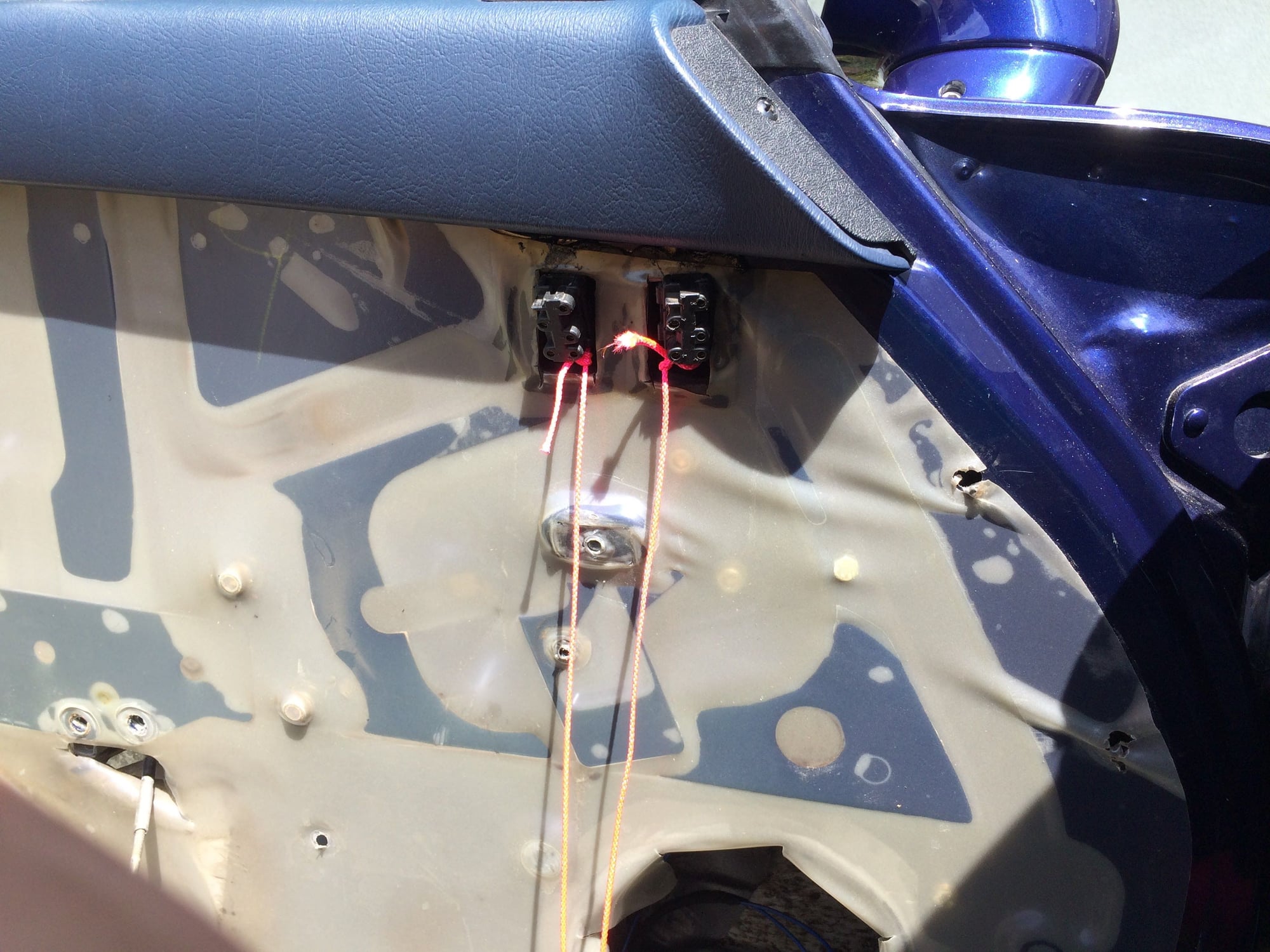
2c. You also want to pop out the window switches. Pry only from the top or bottom to not break the pins holding the frame around the switch. Get some string about 18" long or more, and tie it to the back end of the switch connector in the door. If the switch falls back into the door, you can pull it back out. Now separate the switch from the connector. Again gentle rocking and prying works best to not break anything.
2d. Using a hex wrench (5mm I believe) to remove the 3 bolts holding the grab handle to the door. There are two at the rear and one at the front. Take your time to remove and later when reinstalling them. (I had to redo the threads on one from trying to force it -- not a fun project.)
2e. The door card should now come off easily.
3. To remove the TWEETER you need to do the following:
3a. Squeeze on the cover to release the two tabs that are at the 11 and 5 o�clock position (R side � passenger) and the 1 and 7 o�clock position (L side � driver) and push downward and it should pop out.
3b. The TWEETER is in the cover. Careful when removing.
4. Install new TWEETER and run wires on back side and exit to a location that makes it easy to connect to the crossover.
5. After you have installed the new TWEETER you can reinstall the door card.
6. At this time, you may want to check for any debris in the door itself and clean it out, add dynamat, etc.
7. For more detailed instructions and photos on the door card and tweeter removal you can refer to this thread: Door Speaker Installation - 6.5� Polk Audio - Many Pics
8. Full disclosure � I did a terrible job with removing the TWEETER that the connecting plate came off the cardboard. My solution was to drill out the rivets and using high-quality zip ties (not what you find at the auto parts store) secured them back on. The solution works great � no visible difference from stock.
REAR
If you have a short stub screwdriver, you can do this install without removing the rear parcel shelf.
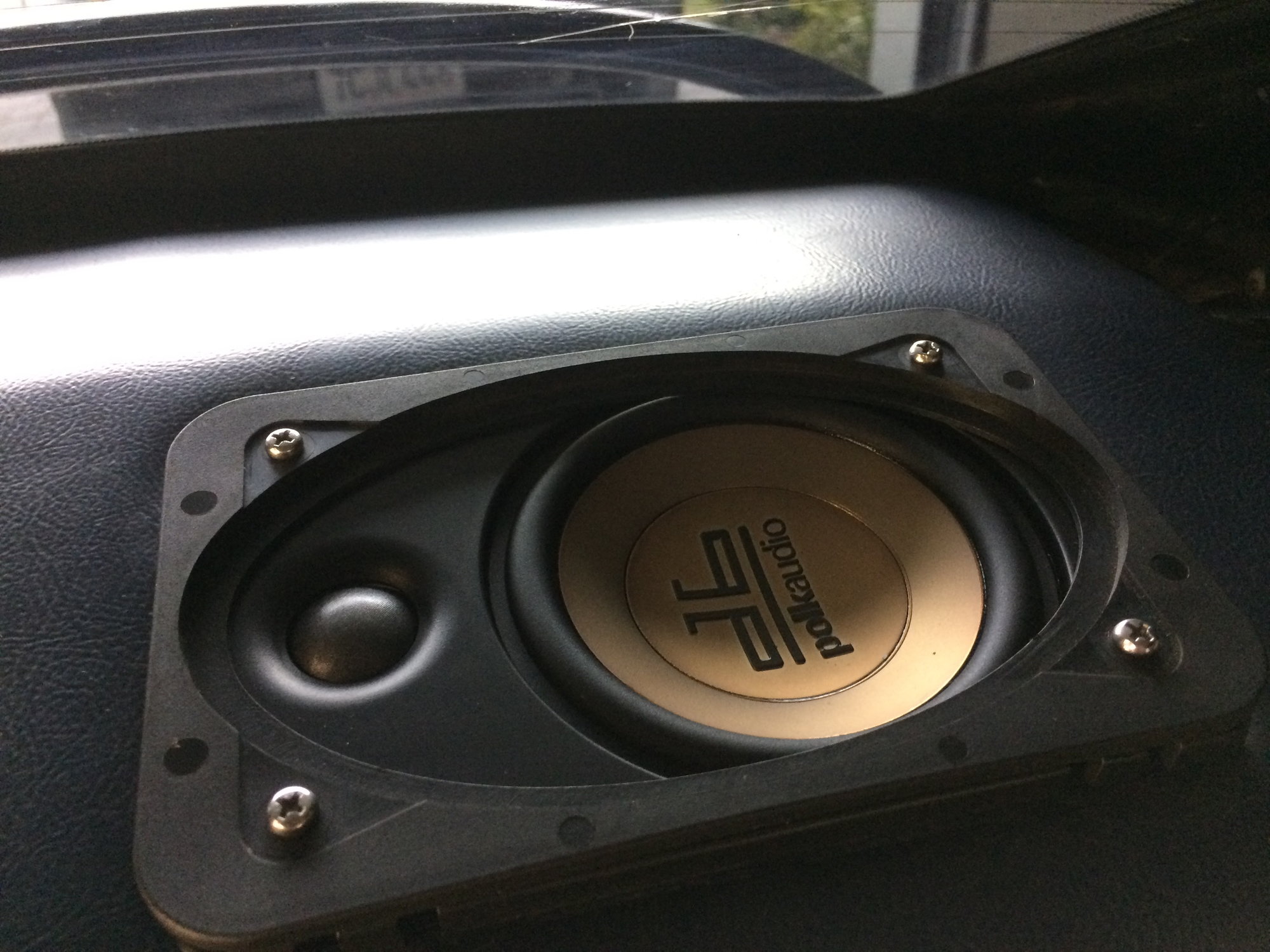
1. Speakers: POLK DB 461p (4" x 6") -- I bought them from Crutchfield and they came with the proper adaptor to connect to the existing wiring. (You might need to ask them about the adaptor just to be safe.)
2. Use a Dremel with sanding attachment to trim down the 4 corners of the speakers. The original speaker grills will now fit perfect without any issue. (I first thought it was the grill snap points that needed trimming and did one to test, and only then realized it was the speaker that needed to be trimmed to fit properly!) A good reminder to always test fit off the car first!
FRONT
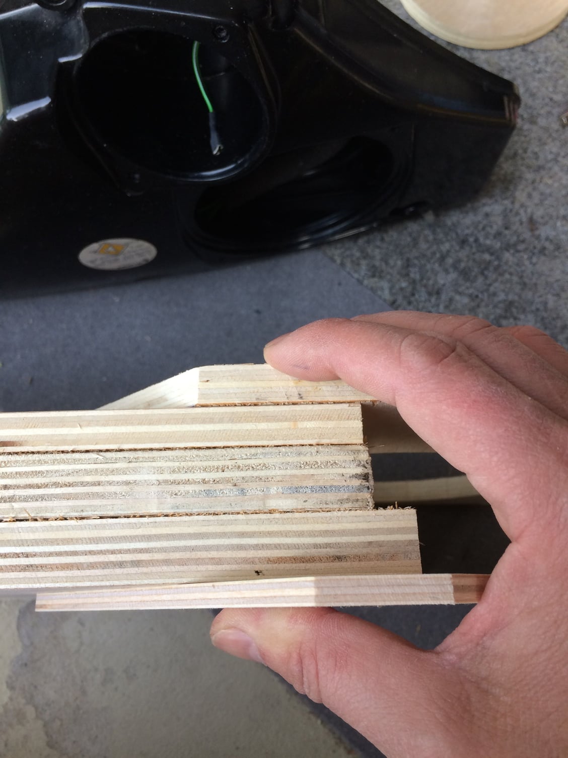
I needed to make a mounting plate to hold the new MID and LOW speakers. I used different widths of high-quality plywood to make it work. I�m used to working with wood and have all the necessary tools. Orchard Supply has some ideal (smaller) sizes to minimize waste. I think I used a 2� x 4� sheet of 1/2� plywood and then needed only 1� x 1� of 3/4� plywood and 1� x 6� of 1/8� plywood. Get extra in case you make a mistake, etc.
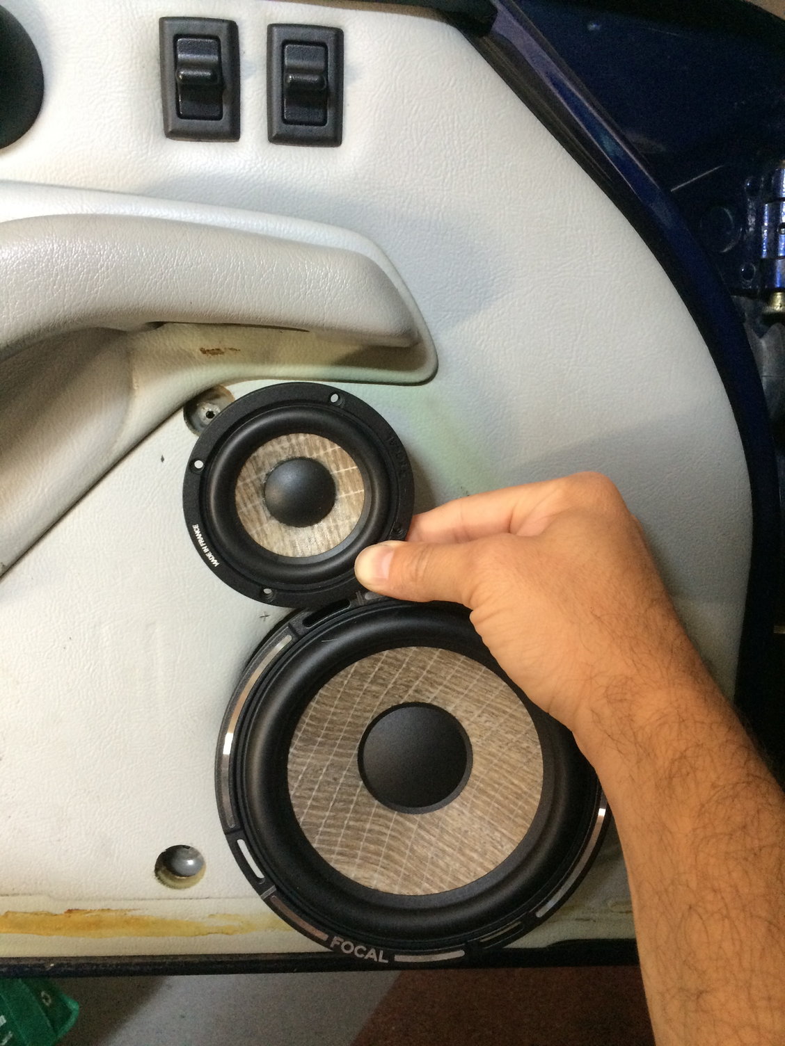
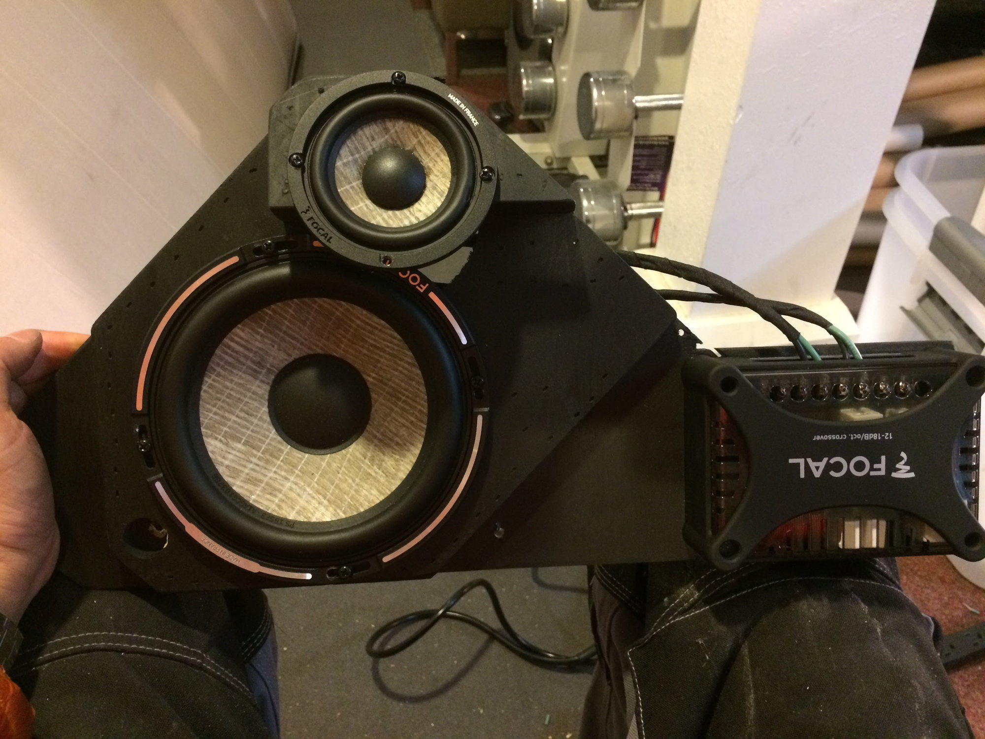
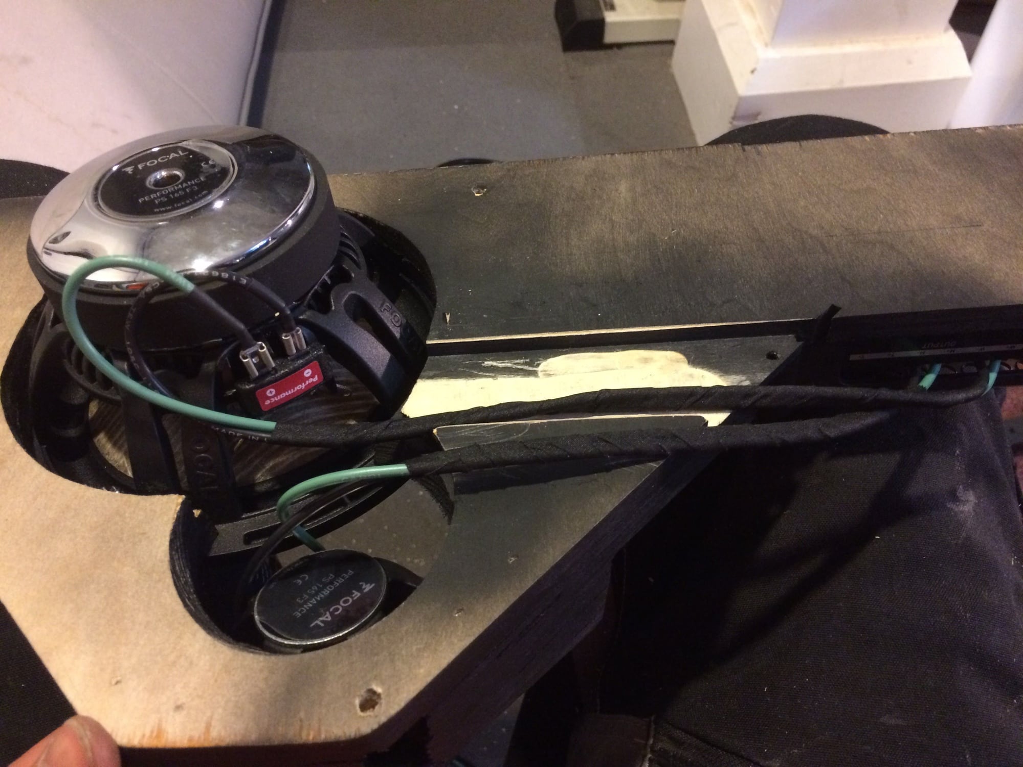
1. Speakers: Focal PS165F3. I read the different reviews and these seemed to be the right quality at the right price for my not perfect ears!
1a. 6 1/2� LOW
1b. 3" MID
1c. 1 1/4" TWEETER
1d. 3-Way Passive Crossover
For my Mounting Plate it required 5 pieces of various thickness plywood.
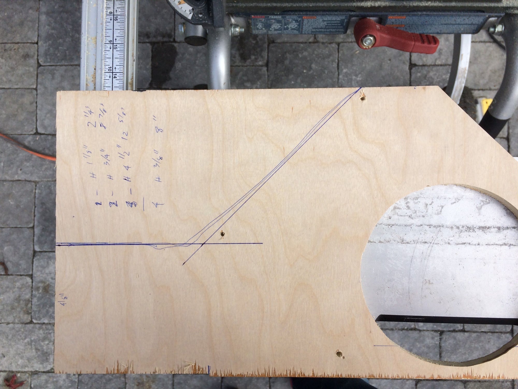
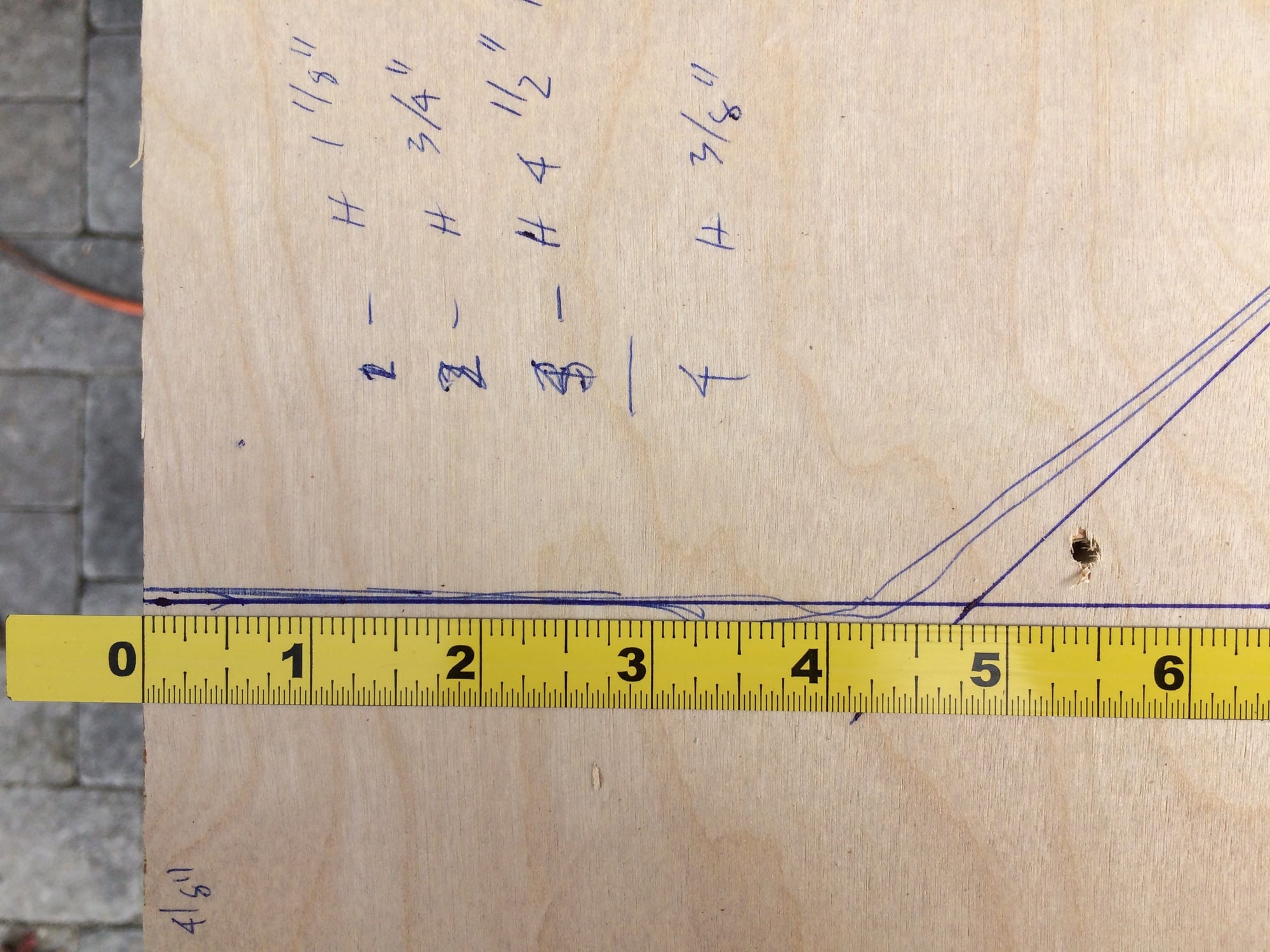
Mounting Plate 1 -- 1/2" thick plywood
1. Height : 9 1/4"
2. Length : 18"
3. Front leading edge
3a. Measure 3 1/2" from bottom and make a 45 degree angle cut
4. Bottom edge
4a. Measure 5" from the back edge and do a cut the width of the saw blade from the back edge to the 5" mark
5. Top edge horizontal
5a. Measure 2 1/2" from the front edge and mark a 45 degree angle to the rear
6. Rear trailing edge 45 degree
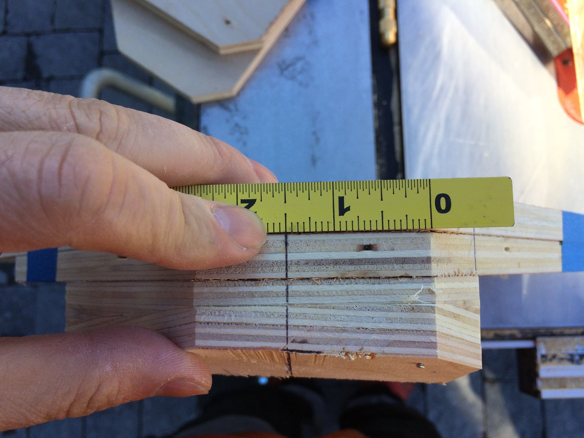
6a. Measure 4 1/8" up at the rear (4 1/4" if you have not made the kerf cut in step 4) and mark a horizontal line. Where the 45 degree angle and this line meet is where you need to make your final two cuts for Mounting Plate 1 (MP1).
7. Mark hole for LOW speaker
7a. 3 3/8" from bottom and 5 3/8" from front -- make a center punch mark. This is the center of your hole.
7b. Wait to cut the hole until Mounting Plate 2 (MP2) is completed.
8. Drill holes for mounting into door -- use 3/16" drill bit
8a. Front : 1 1/8" from bottom, 2 5/16" from front
8b. Rear Lower : 3/4" from bottom, 8 7/8" from front
8c. Rear Upper : 4 5/16"from the bottom, 12 5/8" from front
8d. Top : 3/8" from top, 8 1/8" from the front
9. Use the first MP1 as a template and make the second MP1.
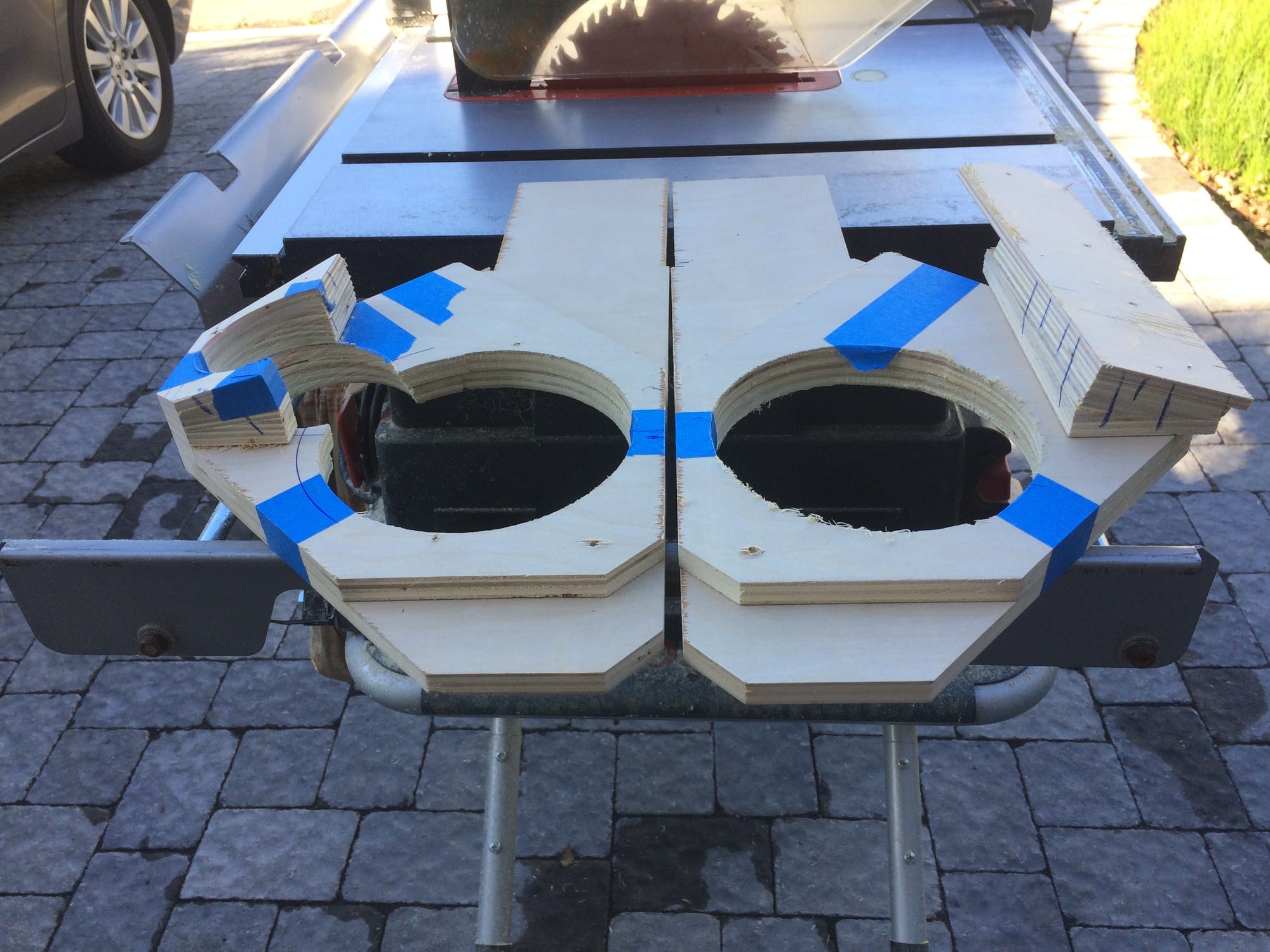
10. After cutting and drilling the screw holes for Mounting Plate 2, then cut all the speaker hole openings for the LOW speaker in both MP1 and MP2. I used a RotoZip with circular attachment to cut the holes. Take your time so you do not break the drill bit and you get a nicer cut. Don't worry that it is not perfect. The speaker will cover it. NOTE: use a center punch and mark the edge of the circle opening, then drill the center hole and edge hole. Then set your circle hole cutter.
CHANNEL FOR SPEAKER WIRES
In my setup I am using the existing wiring to the door (much easier than trying to run new wires through the doors and frame) and mounting the crossovers in the door on MP1. I�ve read about solutions that put the crossovers under the passenger seat in place of the Nokia amp. Both solutions work. For the new wires that run between the crossovers and speakers, you can hide the wires with a channel on the back of MP1 or if you are using thick wire and need more room, you might need to make the channel on the front of MP1 and the same channel on the back of MP2. In my setup I used 16 and 18 gauge wire so I only made a channel on the back side of MP1 to hide the wires.
1. Using a router, you will rout a 1 1/2" - 2" wide by 1/4" deep channel from speaker hole to the Rear Upper screw hole. Use the Rear Upper screw hole as your center line and make a horizontal channel to the LOW speaker opening. NOTE: When the MP1 is mounted you should NOT be able to see the channel you made.
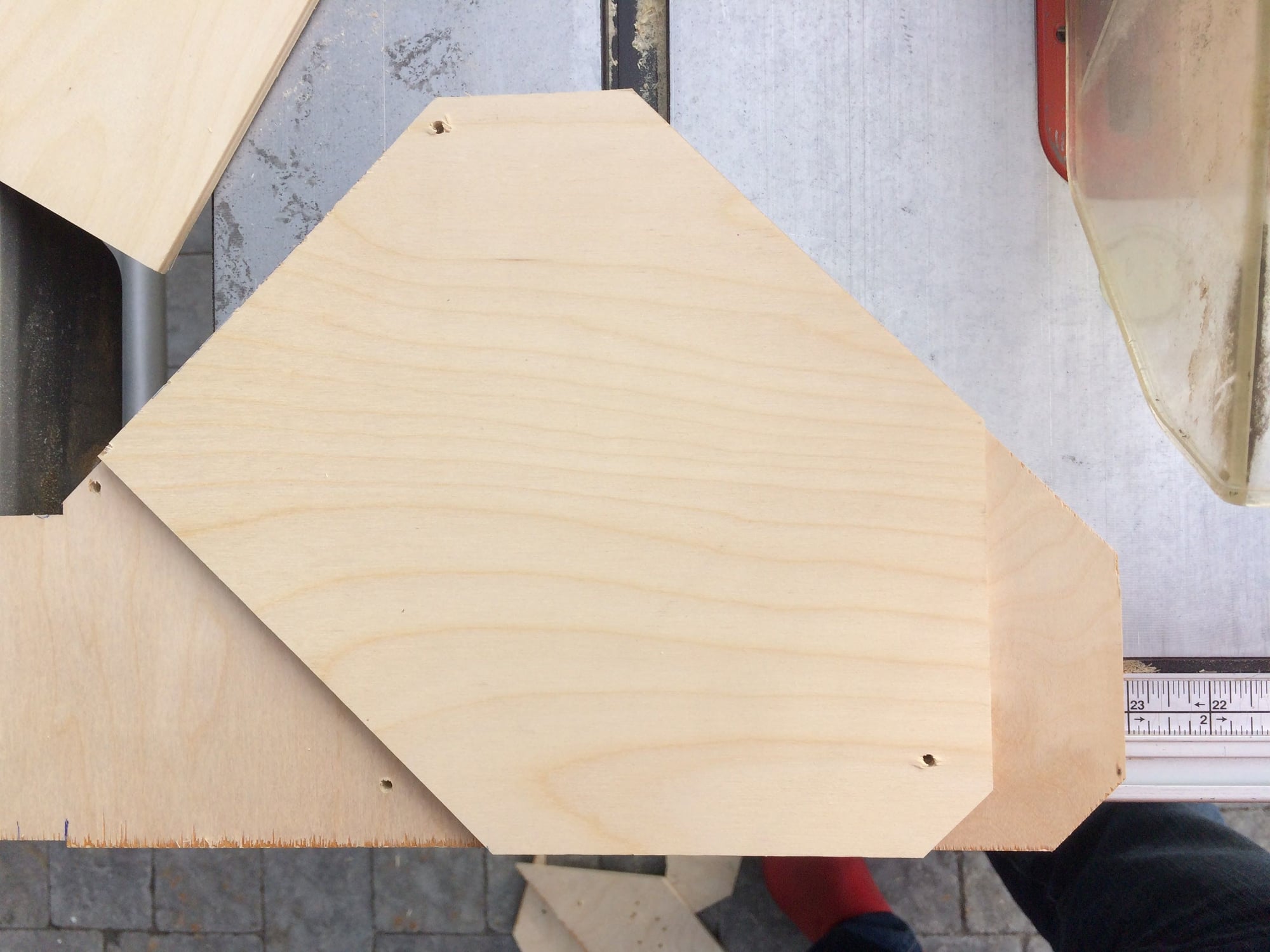
Mounting Plate 2 -- 1/2" thick plywood
Add to MP 1 and this becomes the base for the LOW speaker. I cut it in such a way that only two mounting screw holes (top and front) go through MP2. I will inset these holes so that I can use the original mounting screws. Use MP1 as a template for the holes to be drilled. I started the front edge of MP2 1 5/8" from the front edge of MP1. This helps to follow the curvature of the HiFi door cover which is narrow at the front.
1. Height : 9 1/4"
2. Use MP1 as a template (important to mark the center point for the speaker holes before drilling) and drill all holes. Repeat for a second MP2.
3. Trim to fit MP1 -- cut front and rear 45 degree angles at the top half.
4. Rear angle end point on the bottom edge is 6" from the front of MP2. Then cut the 45 degree angle. You should be clear of the rear mounting screw holes in MP1.
Mounting Plate 3 -- 3/4" thick plywood
These will be cut oversized initially in order to drill the speaker hole (use a hole saw drill bit as that will be much easier). They will also be cut at an angle to get the speaker at a better position like the originals.
1. Height : 2 1/2"
2. Length : 9 1/4"
3. Cut MP 3 with a 7 degree angle along the entire length of the piece. The base should be as close to the original thickness of 3/4".
Mounting Plate 4 -- 3/4" thick plywood
Like MP3 these are cut oversized initially and then trimmed and drilled afterwards. These are cut at a 7 degree angle lengthwise and at a 5 degree angle width wise -- what you are doing is angling the speaker mount upward and rearward. Most likely you will need to make a jig to make this cut. NOTE: It took me 8-10 practice cuts to determine the angles I wanted.
1. Height : 2 1/2"
2. Length : 9 1/4"
3. Determine your best method to cut MP4. I made a simple jig and was able to make one pass to cut both angles.
Mounting Plate 5 -- 1/8� thick plywood
Stack all the mounting plates up and determine the overall thickness at the leading and rear edge at the top. You want to be as close to the original position as possible. For MP3, 4, 5 -- they should extend only 1" forward of the front leading edge at the top. This is important to make sure the Mounting Plate does not rub against the HiFi door cover.
1. Front leading edge top : 1 3/4"
2. Front leading edge bottom (at the bottom of MP \3+4) : 2 1/4"
3. Rear trailing edge top : 1 3/8"
4. Based on the measurement you get with the MP1-4 stack, you will determine what additional width you need. I added an additional 1/8" thickness plywood to my stack.
5. Once you have the width, then you need to connect all the pieces. I used a braid nail gun to connect the MP's together. I then trimmed MP3, 4, 5 to the existing MP1 & 2. It is important that the height of your Mounting Plate must not exceed 9 1/4"!
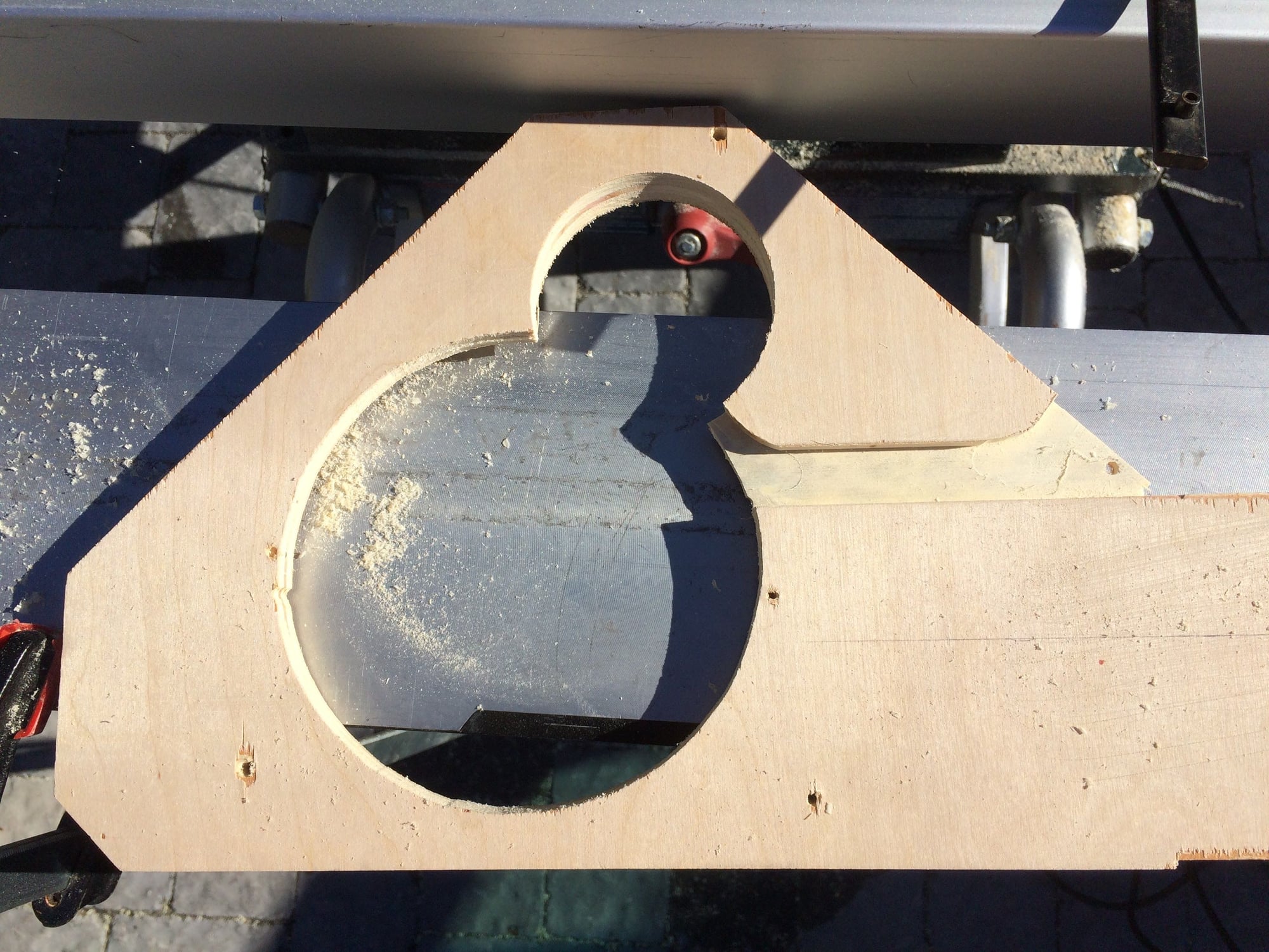
6. Centerline for the MID speaker is approximately 1 1/2" from the front leading edge at the top.
7. Mark the center of your speaker hole based on your specific speaker size. 8. Remember to accommodate for the speaker frame. The edge of the speaker frame should butt to the top of the Mounting Plate.
8. Drill the MID speaker hole. I used a hole saw drill. Remember to drill 90 degrees to the angle of the final MP. Drill all the way through the Mounting Plate.
FINAL FINISH
1. Drill the inset holes for the front two mounting screw holes. You will be drilling through MP2-5. I have a drill press and Forstner bits which made it easier. The hole needs to be about 25-50% larger than the screw head.
2. Lightly sand all the sharp edges to bevel/round the edges and corners.
3. Paint the wood with matte black quick drying paint.
4. Do a test fit and confirm all the mounting screws go in easily. If necessary make the holes slightly bigger.
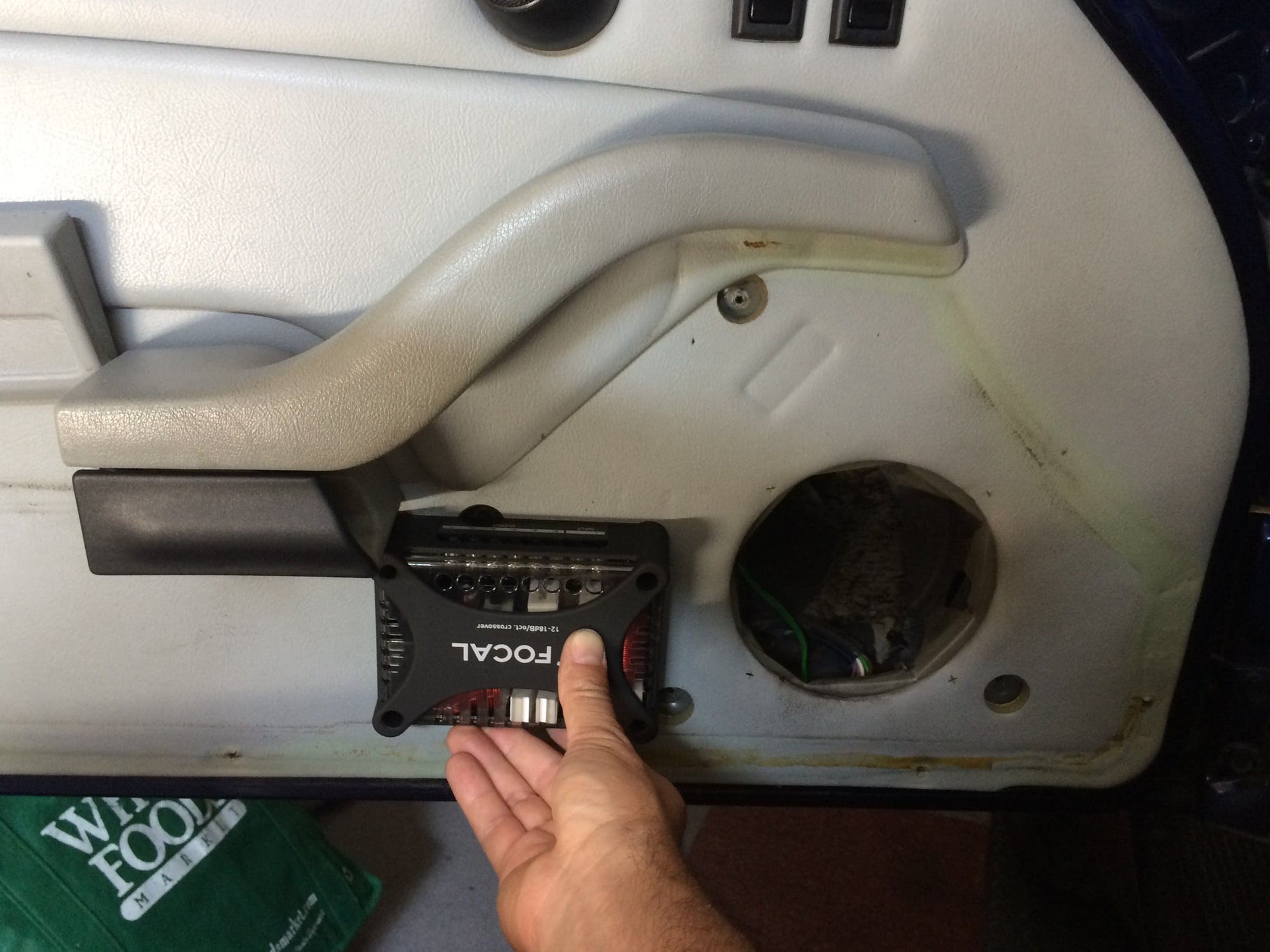
5. Install crossovers
5a. Connect MID and LOW wires to crossovers (I made custom speaker wires, just because)
5b. Mount crossover to Mounting Plate at the rear. Center top and bottom.
6. Install MID speaker
6a. Note location of speaker wire connection (rotate to best location)
6b. Run wires through channel, give extra play and then cut and put in fittings as necessary.
7. Install LOW speaker
7a. Note location of speaker wire connection (rotate to best location)
7b. Run wires through channel, give extra play and then cut and put in fittings as necessary.
8. Connect TWEETER wires to crossover
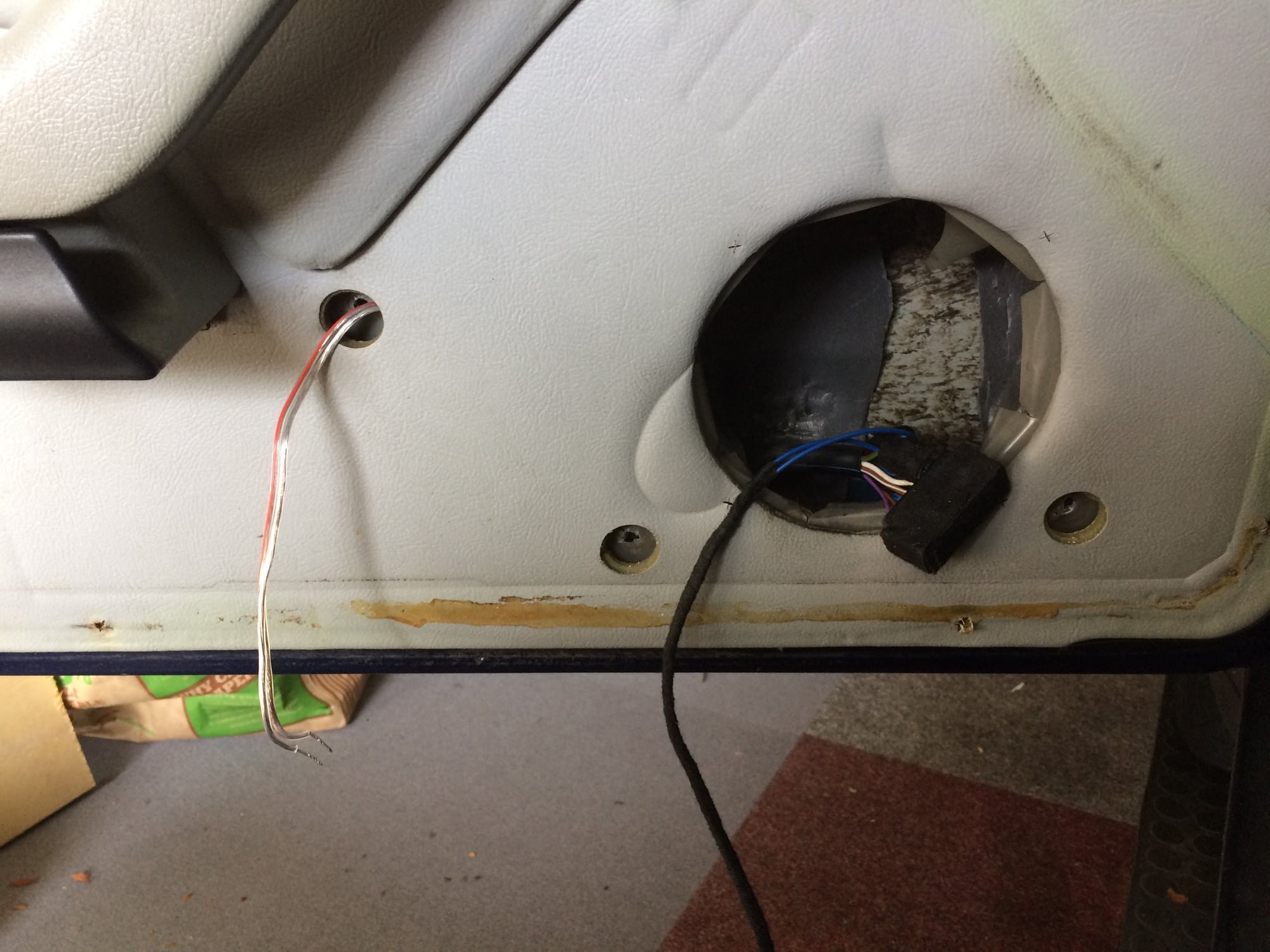
9. Splice into existing speaker wiring and connect wires to crossover. I connected to the LOW speaker input wires based on my connection from the head unit to the amp bypass connector.
Driver side (L)
Positive -- Green wire
Negative -- Green/Brown wire
Passenger side (R)
Positive -- Purple wire
Negative -- Purple/Brown wire
10. Test speakers before mounting
11. Mount speakers using the four mounting screws. On my setup I only used three of the four screws.
12. Install the HiFi door cover.
13. You are done!
IMPT: Measure twice, cut once. Test, test and test fit before doing the final connection or cut. Slow and methodical for best results!
Photos with captions below:
Rear speaker -- perfect fit, but need to round the corners to fit the grills
corners trimmed
Speaker test fit
Crossover test fit
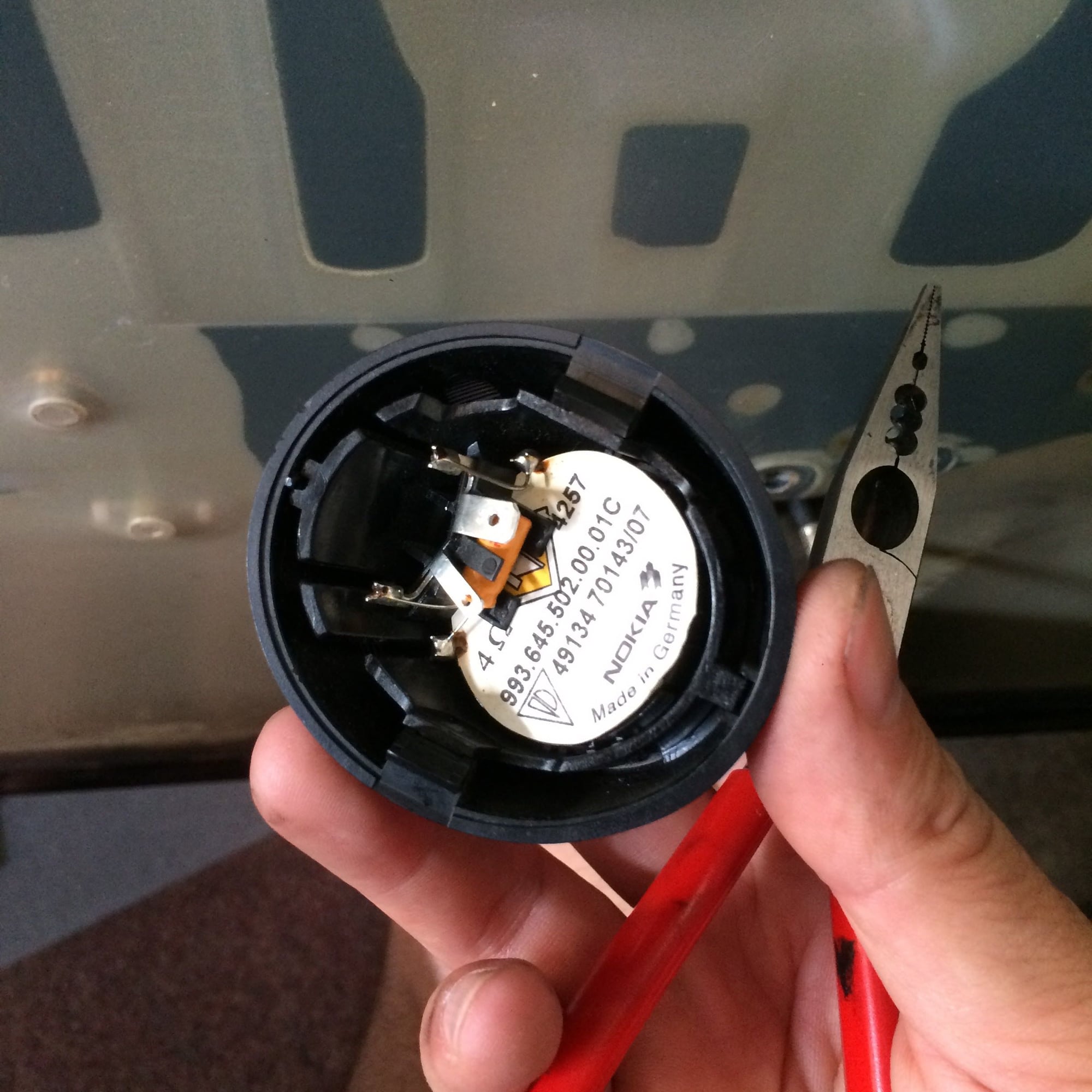
original tweeter
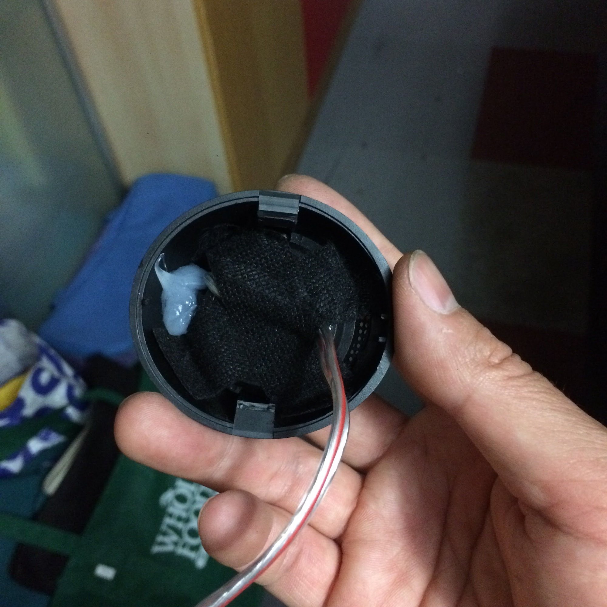
new tweeter with dab of silicon to hold at correct angle
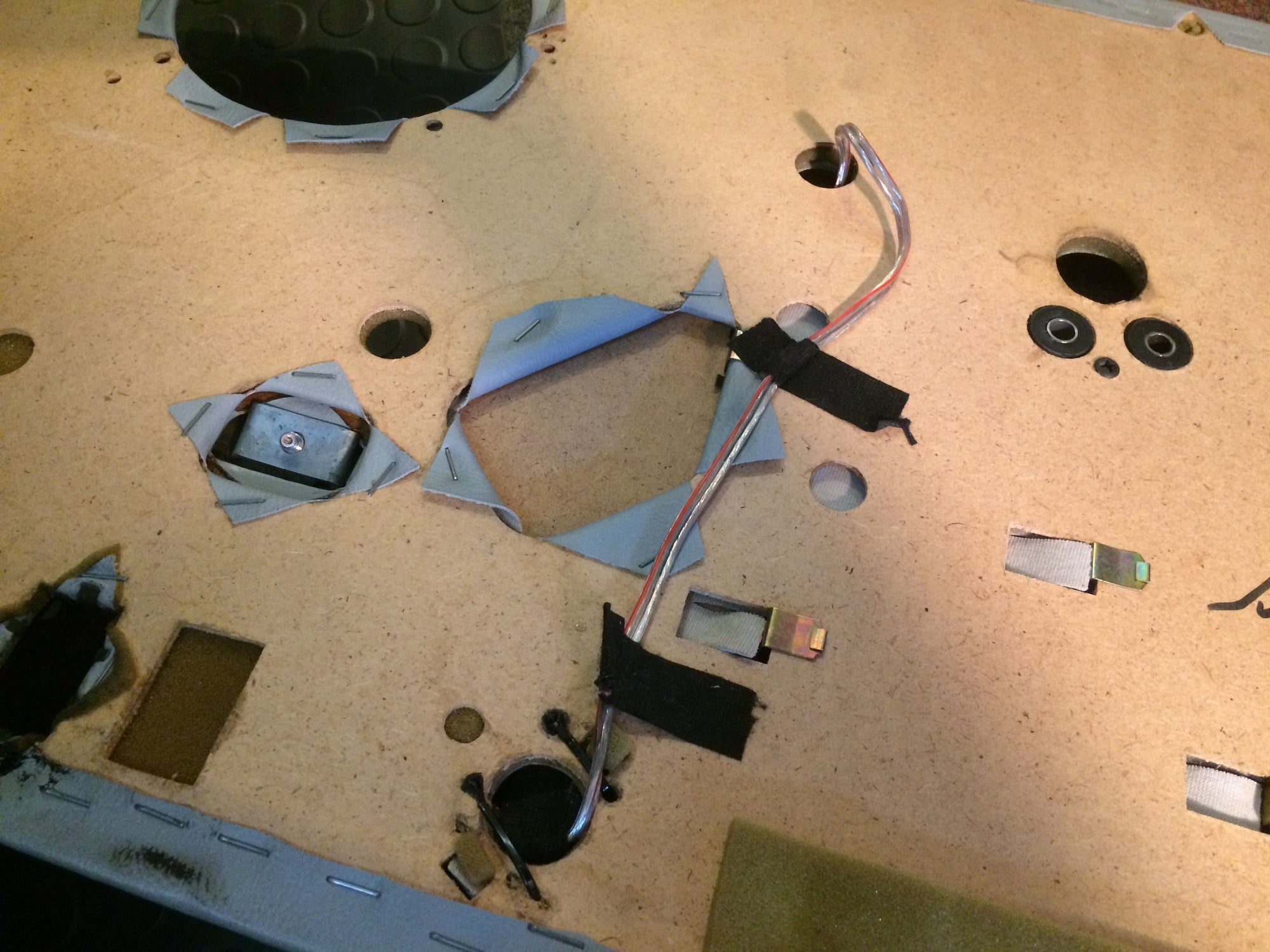
rear of door card showing tweeter wire
tweeter wire through mounting screw hole
string to hold window switches
MP1 in progress
MP1 in progress
MP2 and MP1 cut and mounting holes drilled
stack of plywood
distance of MP2 from leading edge of MP1
Almost done. See the MID speaker hole cut on the left
Centerline for the MID speaker
Channel for wires on back side of MP1
Splicing into LOW speaker input wire
sanded and painted
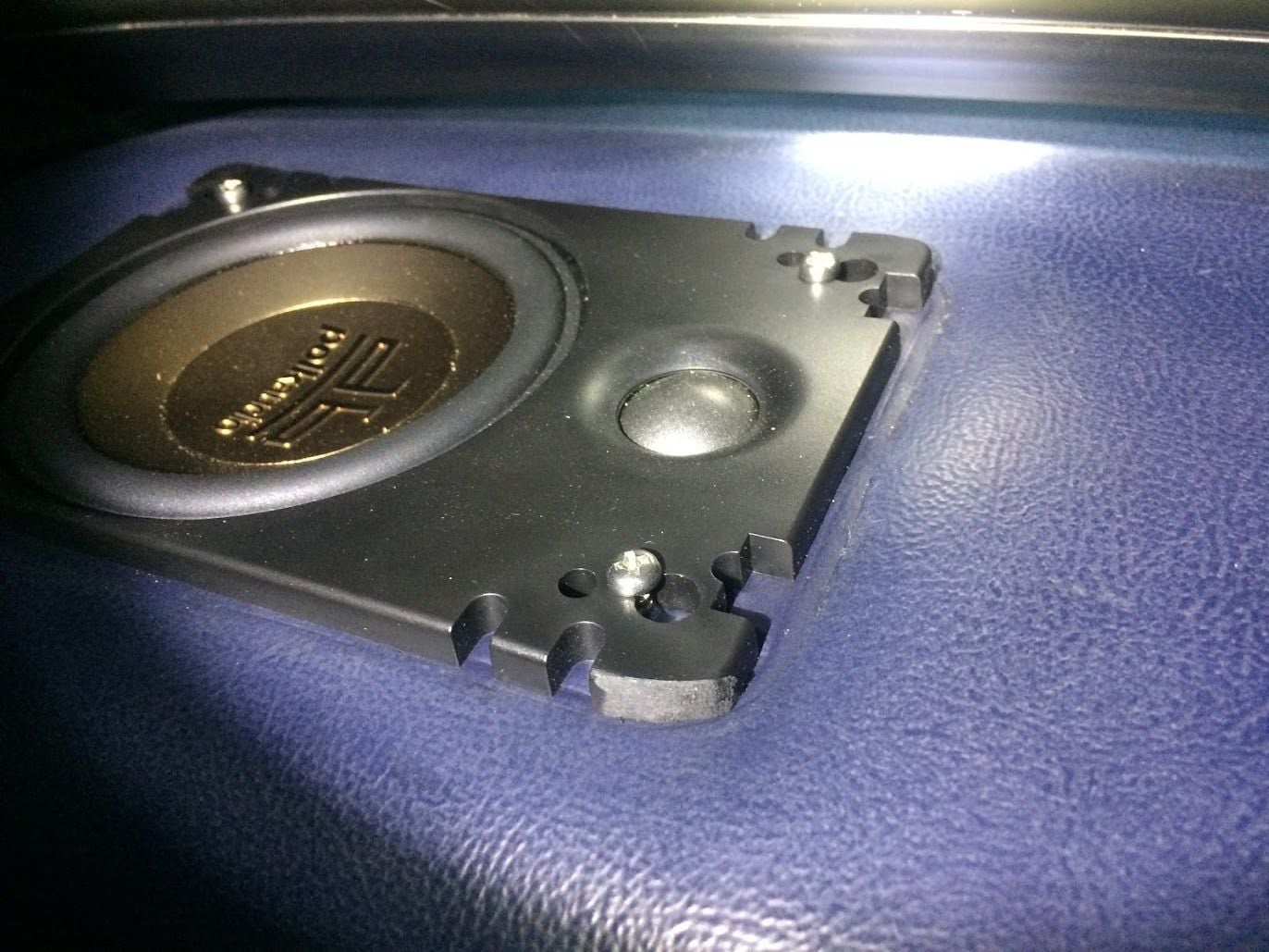
Comparison of original black box and new mounting plate
~ The Eagle ~
---------------------
'96 Polar Silver/Black C4S, manual, litronics, LED's in the positioning lights, alu/leather shifter & handbrake,
silver face gauges with alu rings, hardback sport seats, leather interior, motor sound airbox, stainless door sills,
valve caps Porsche crested brushed alloy, front protection bar, with split rear grill and layered with Meguiar's NXT Tech Wax
__________________
'92 Carrera 2 (Sold)
'89 Carrera 3.2 (Sold)
Yes, very impressive work. I did a similar thing about 4 years ago. But, back then, I could only find a 2-way Focal system with crossover. I don't think this 3-way system wasn't available. I ended up building just a single mounting plate with offset rings for the 6 1/2" woofer and then mounted the tweeter with it's own external housing on the same board and left the original tweeter unconnected. But I really like your setup better. Would prefer to have a true 3-way system as was designed for the car.
I have a few questions though:
1) The wiring harness you bought from Tore says it replaces both the wires going from head unit to under passenger seat so as to mount new crossovers there and then another harness from under seat to doors, right? If you placed your crossovers in the doors instead, what part of his harness did you keep and how did you hook-up? I'm confused.
2) You also eliminated the amplifier under seat, right? So what sort of power output do you have with just the Porsche Classic Radio in place? Do you get a lot of distortion at full volume?
3) Have any pictures of final setup with speakers all in place in doors and head unit?
4) My knowledge of crossover technology is limited, but I'm wondering if I can keep my woofer and tweeter and just add their 3rd speaker, or do I need to get their crossover since it separates the mid-range as well? Mine are also Focal speakers of roughly the same size and impedance.
Very, very happy with the sound. I read in a different post to put the levels for BASS and TREBLE to zero and adjust the MID first, then add back the BASS and TREBLE as needed. Adjusted the front to rear balance (think it is -1) and the sound fills the cabin nicely.
Radio reception is still a bugger and that is my next trouble shoot. Stay tuned for that post.
FM radio reception highly depend on the antenna amplifier. It needs +12V power feed when the radio is on. This is the thin wire bundled with the antenna coax cable.
Cheers,
Tore
Here are some answers to your questions. (I'm not a power user, so not sure how to do all that fancy quoting, etc.)
1) The wiring harness you bought from Tore says it replaces both the wires going from head unit to under passenger seat so as to mount new crossovers there and then another harness from under seat to doors, right? If you placed your crossovers in the doors instead, what part of his harness did you keep and how did you hook-up? I'm confused.
Yes a good question. The two parts of Tore's wiring meet at the amp. You get wires for the following
a. FR -- LOW
b. FR -- MID
c. FL -- LOW
d. FL -- MID
e. RR
f. RL
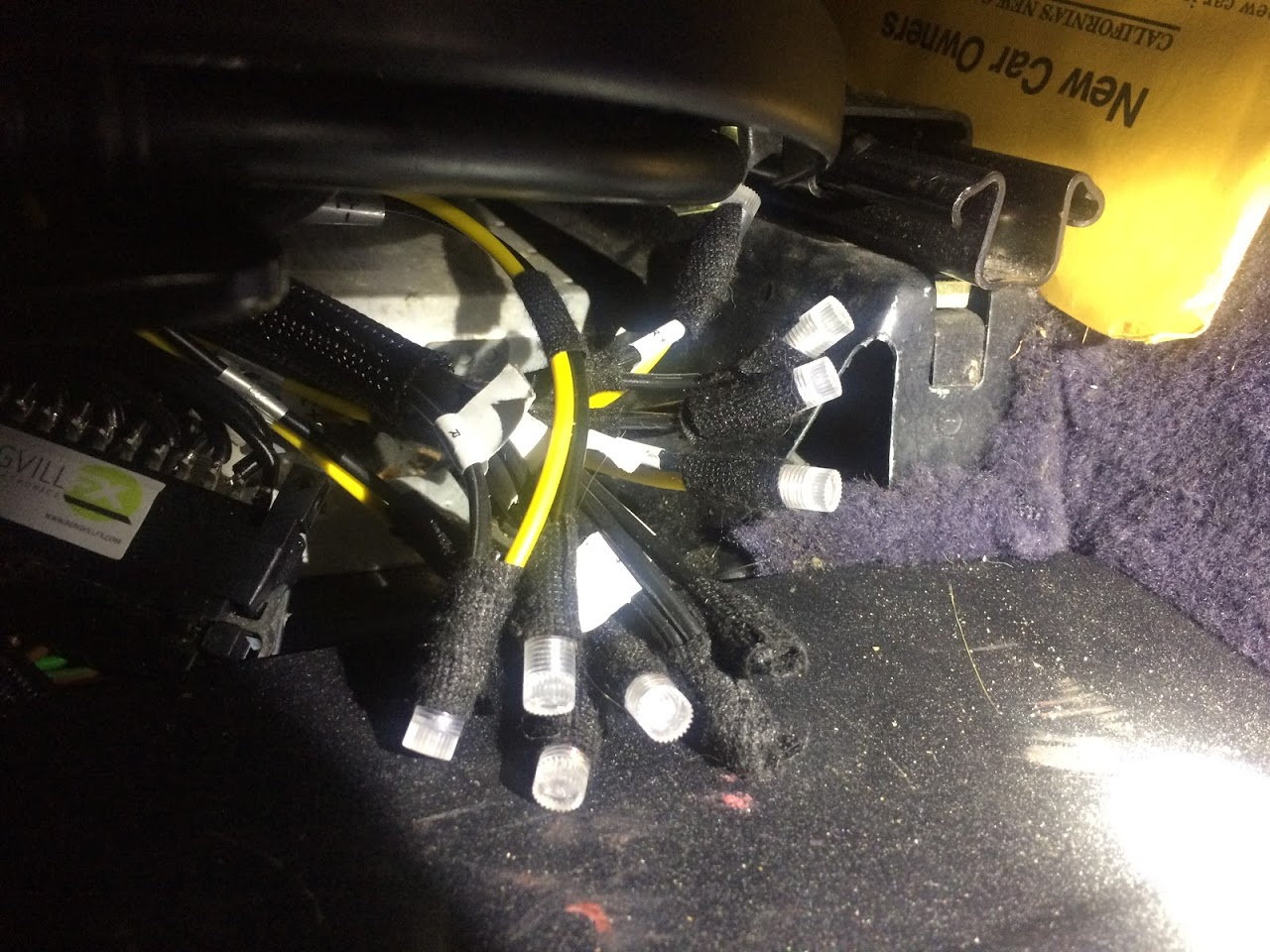
The other end of Tore's adapter connects to the existing connector that exits the amp. Thus sending the signal to the existing wiring for the speakers unadulterated. As I have the crossovers in the door, I did not connect the MID wires -- no need -- as the LOW wires carries the full signal from the head unit. That is why I spliced only into the LOW wires at the door. NOTE: remember that in the original setup the TWEETER is wired in parallel with the MID (there is a capacitor), thus not a separate wire for the TWEETER. Here is a photo:
Still plan to do some work under that seat and will clean it up more.
Why Tore suggests (I am assuming a bit here) the crossovers under the seat is if you are still going with the existing speaker system that still connects the MID and TWEETERS together. That does not work when the tweeter is separate. See his diagram below:
2) You also eliminated the amplifier under seat, right? So what sort of power output do you have with just the Porsche Classic Radio in place? Do you get a lot of distortion at full volume?
The power seems great to me with just the Porsche Classic Radio -- but my ears are not what they used to be. I've gone up to "9" (not "11"!) and don't hear any distortion. I am still considering the additional of an amp in the future. Don't think it will change my set-up in any way except now I will have an amp between the wires coming from the head unit and the wires exiting to the adaptor. I will probable need to make proper end connectors, thats all.
3) Have any pictures of final setup with speakers all in place in doors and head unit?
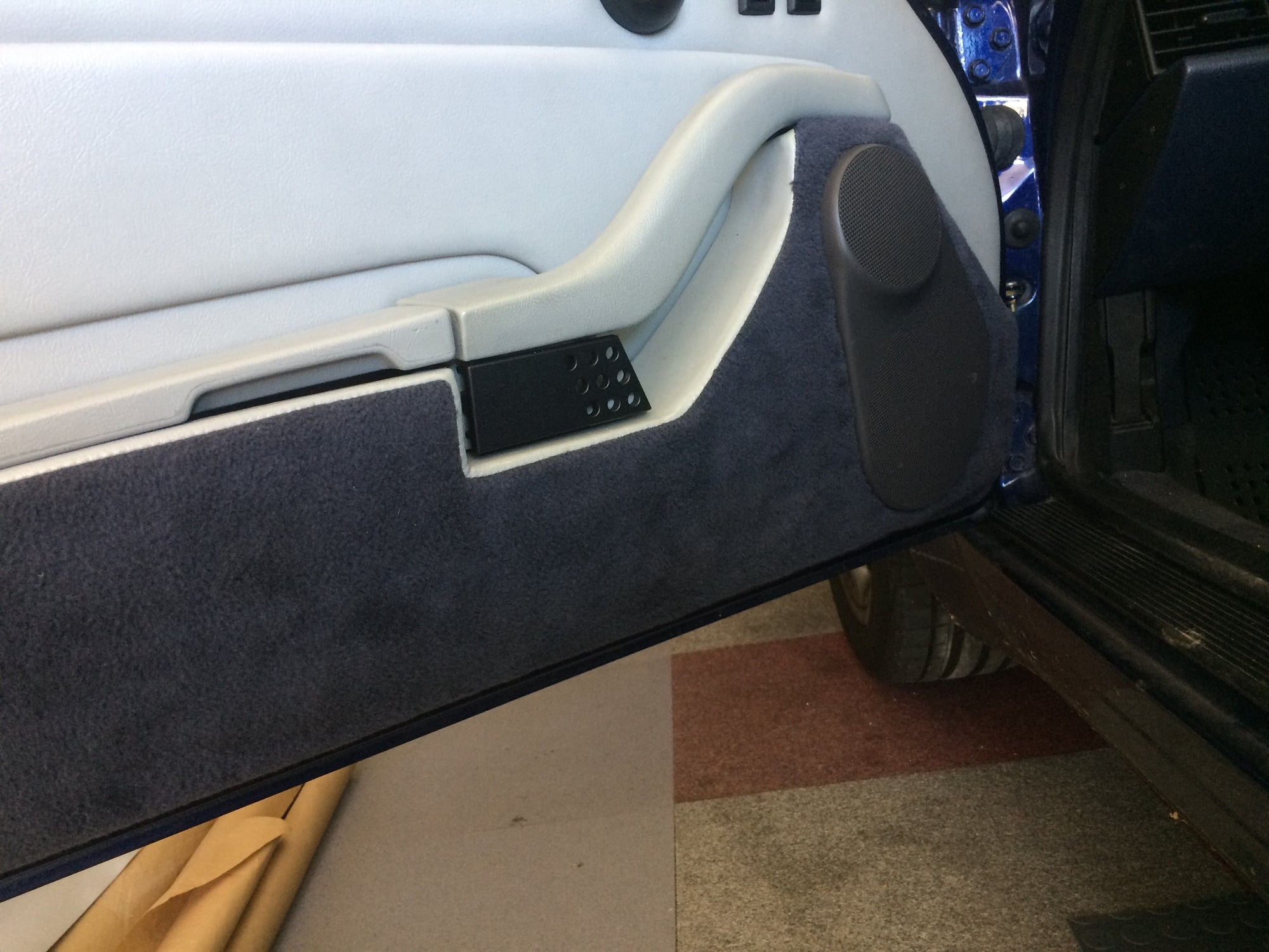
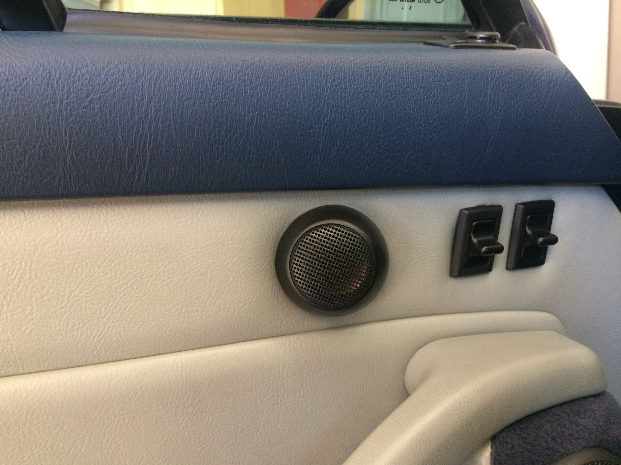
Here are the photos below. It all looks stock. The cover fits perfect with no binding on any edge.
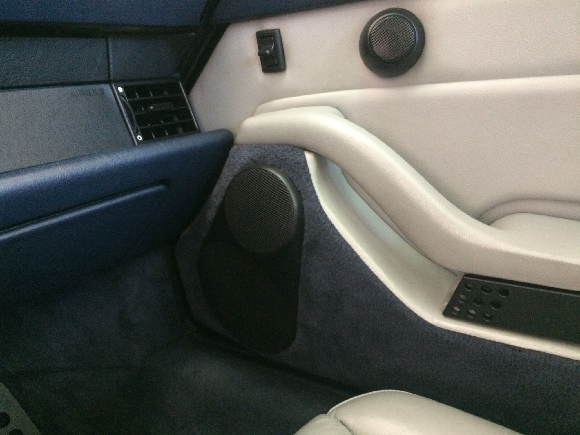
Left door -- perfect fit
Tweeter
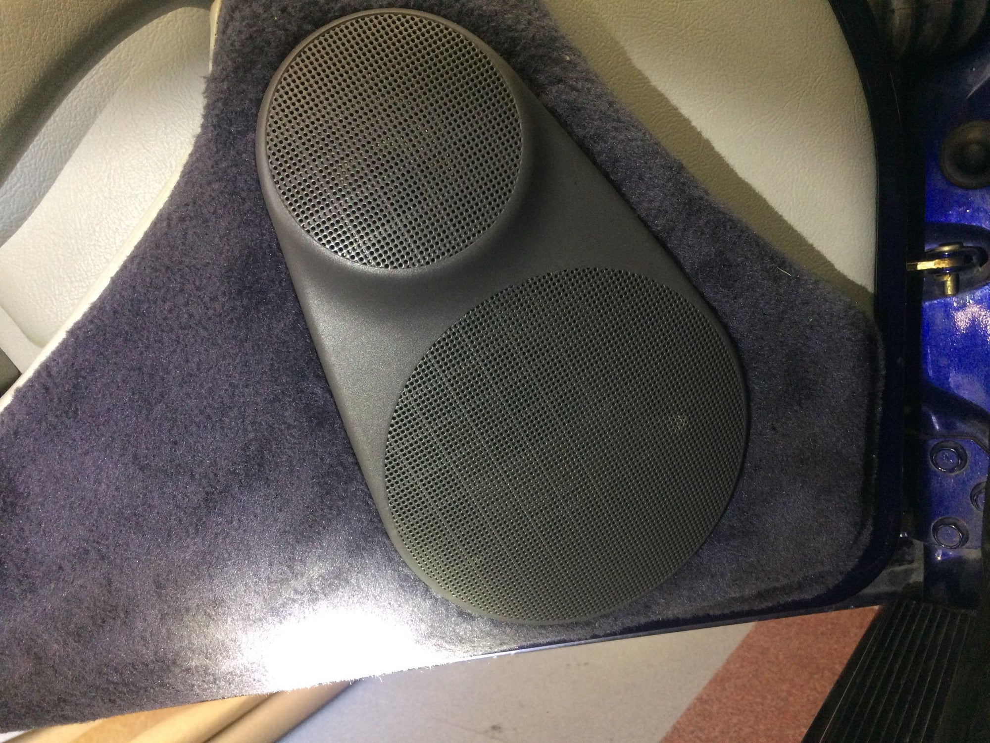
MID and LOW with light to show speakers
MID and LOW with normal light
Porsche Classic Radio
Right door
Rear speakers
4) My knowledge of crossover technology is limited, but I'm wondering if I can keep my woofer and tweeter and just add their 3rd speaker, or do I need to get their crossover since it separates the mid-range as well? Mine are also Focal speakers of roughly the same size and impedance.
Very good question. For sure you can keep your existing speakers (Initially I was going to make a custom set of speakers from several Focal kits and sell the rest off, but since the larger 6 1/2" fit, I went with this system.) So all you need is their 3-way crossover. I've seen versions on eBay, but there may be other sources as well.
FM radio reception highly depend on the antenna amplifier. It needs +12V power feed when the radio is on. This is the thin wire bundled with the antenna coax cable.
Cheers,
Tore
Hi Tore: Yes you are correct. That is connected and sending 12v. (will recheck that it is not less). I still get spotty FM on some stations depending on location, etc. -- that annoying background static. When listening via my bluetooth to my phone the sound is clear.
I installed a new antenna amp + wire to head unit (my old one I did a repair on the antenna wire as the end had broken off -- thinking that my soldering was not 100% decided to try a new unit) and seems like it is worse than before. I also rerouted the GPS and microphone wires into the same hole as the antenna (previously they ran a different route).
So that is my next project to troubleshoot this and determine if I am getting interference from the GPS wire perhaps or??? But that is for another post.
An excellent post that will be most useful for a serious audio upgrade project. Thank you for taking the time to write and post it. Collective knowledge of Rennlist is very valuable.
Great write-up will, & xlnt work!
I have a friend that lives up there close to you...
Any chance you might be willing to make up some more of the wood front speaker adapters?
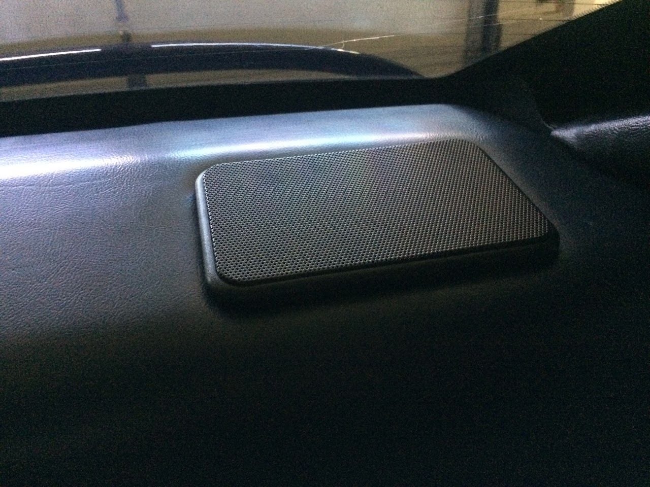
Is that the factory speaker grill in the rear package tray?
They seem different in the 97-98 cars with the Hi-Fi option?
hi drb930 and t16 -- thanks for the kudos on the work. I got a message from someone else on the forum to make a set. Not looking to do a side business, yet am willing to help out folks on the forum. Let me know how serious you are -- since I am making one, I could do a few more at the same time. IM is probably the best.
To your question Dave, the Targa rear speakers and grill are different from the Coupe with the Hi-Fi option. The concern is that when the glass roof rolls back it would hit the speaker grill. I personally like the look of the Coupe speaker grills.


 12-20-2016 | 08:00 PM


 thank for documenting the process!