When you click on links to various merchants on this site and make a purchase, this can result in this site earning a commission. Affiliate programs and affiliations include, but are not limited to, the eBay Partner Network.
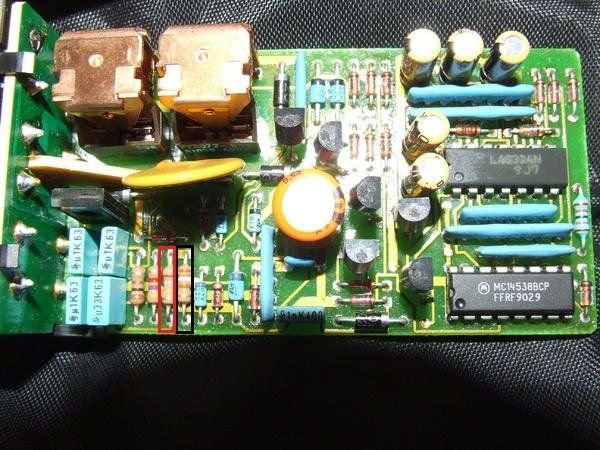
I recently stumbled across a post by mojorizing showing how to modify the spoiler control module to increase the speed at which the spoiler goes up (and down as well). By swapping out one or two resistors the speed can be raised to anywhere from 60-80mph.
It sounds like it functions pretty much like the RUF version, and a whole lot cheaper for anyone with modest soldering skills and who can read resistor band codes (or use an ohmeter).
So, does this work on the 993 or not. The linked thread is in the 964 forum. On the last page Loren B states this is not for 993, but earlier it is stated that the 964 module was used in 993 for some period. Anyone know for what manufacture dates this mod would still apply?
This part was cut off from the bottom of the above picture: �1/4 watt +/- 5% resistors are fine, and your speeds may vary a few mph's due to slight differences in the capacitors used in the RC timing circuits on your particular module, but these graphs should get you in the ball park using available resistor values.�
Fnckr, the two versions of the spoiler module have the same part # so you�d have to pull yours and remove the plastic case to confirm what you got.
Mine was a January 1996 build, the spoiler module was the later version which had the same part # but completely different internals. It cannot be modified as described in the 964 forum.
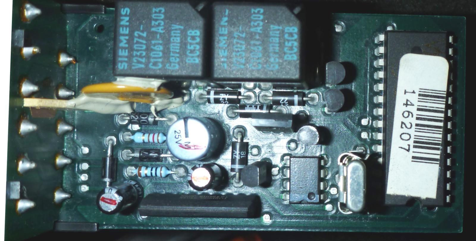
The modifiable spoiler model looks like this:
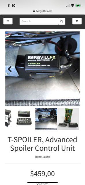
If you�re unlucky and have the new version you may want to look at the much more modern solution that Tore Bergvil offers on his web store:
I hope to recruit the collective wisdom on this thread without hijacking the original posting...
Without getting too much into the weeds, I wonder if the control unit modifiers can help me understand the problem that I’m having with the rear-spoiler switch wiring. It seems that the PO (or his wrench) spliced a separate wire from the switch UP position (pin-9 on the controller) and ending (with 15A fuse) at the ignition switch harness… does this makes any sense to any of you (?) —why power pin #9 on the spoiler control module (normally it gets permanent 12V to pin #6 and switched 12V to pin # 7). The unintended consequence is a no-starter response condition. My hunch is that this results / pulls-down the voltage supply to the starter solenoid, below threshold level needed to activate the starter -- as serendipity would have it, toggling the UP-switch position (not DOWN), prior to ignition switch - starter engagement results in normal START. This gremlin showed its ugly head after the p-car (08/94 build date) was not used and left on a trickle charge for few weeks...
I sure hope you can shed some wisdom / light on this dark event...
Where does the wire that's tied to pin 9 on the spoiler controller go at the ignition switch harness? Controller pin 9 (and controller Pin 10) get grounded when spoiler is up or down so hard to believe the other end of that wire goes to a source of 12v because the fuse would blow when either spoiler limit switch closed. Any other hacks made by the PO besides the pin 9 wire, either at the lid or at the ignition harness?
When I probed pin-9, measured 2.6v at rest and 10.6v with ignition switch-on (discovered days later that the auxiliary 15A fuse located at the ignition harness was blown). Back injury prevents me from excavating further the ignition harness area. No other mods to the spoiler limit micro switches or motor drive cable were noted. Pure intuition (informed ignorance) led me to check and replace the 15A-fuse; the engine started and runs normally, no longer requiring the precondition of toggling the spoiler UP-switch. Zero intuition on what was done to the control unit itself (-no visible signs of invasion) and hope others might here…(?)
Many thanks to Tore for providing the spoiler circuit schematic and Jay for the many cogent suggestions!
Might be some kind of hidden kill switch so the car won't start.
I've often used some existing witch for this.
Lots of guys wire alarms like you have to put on the right turn signal for instance for the car to start.
^^^ My thought too. The PO may have hacked the spoiler up/down control switch as a convenient way to generate a momentary 12 v pulse to drive "something" else in the car, possibly a homemade anti-theft circuit tied into the start logic. Whatever or wherever it is, it's probably on the other end of that wire.
OK, I did the "convert spoiler operation to manual control" as detailed in post #1 yesterday, and like some other folks, all ten wires instantly came out of the connector and it was a pain to get all of them back in place.
Also, I discovered that there is live power on at least one of the connectors, so I blew a fuse when some of the loose pins touched each other.
But I'm glad I did this. Now you operate the rear spoiler with the switch.
Just hold the switch about 8 or 10 seconds and it will move fully up or down.
If you put it up it stays up (even if you turn the car off).
If you put it down it stays down (even at 200 mph).
Here are possible revised instructions. Use at your own risk.
The suggested revisions are:
1) disconnect car battery
2) pop the cap off of the connector while keeping the connector attached to the module. This will help keep the ten wires in their correct position. Then remove the two wires as instructed.
First, disconnect the car battery. (At least one wire in the connector has live power even with the car switched off.)
1. Go to passenger side footwell and remove floor mat.
2. Look up under dash and locate a black plastic box/module about 2"x4" encased in an aluminum bracket.
3. Use a philips screwdriver and remove screw.
4. Pull module out and let hang.
My suggestion is that you do NOT unplug the connector from the module. 5. Insert flat screwdriver as shown and gently pry connector away from module, taking care not to damage the plastic.
6. Place module out of the way. The mod is to the connector/harness only.
Using a small screwdriver or angled tool, pry the cap off of the connector.
(Do this while leaving the connector attached to the module- this will hold the wires in place. If necessary, pull the connector out a small amount, maybe 1/8", if necessary to get clearance to pop off the cap.)
7. Again use a flat screwdriver to gently pry the cap off of the connector harness.
8 . Be very careful here. Once the cap comes off, the pins may pop out of the harness. If you leave the connector attached to the module, the wires will be held in place.
9. Gently lift/pull out pin #8 and #12 (one is green and one is white/red).
10. Fold the 2 pins against the wiring loom and snap the cap back onto harness.
11. Tape off (insulate) the 2 exposed pins and zip tie to wiring loom.
12. Reconnect harness to control module.
13. Insert module back inside aluminum bracket.
14. Secure with screw and replace carpet.
15. Now go for a test drive
. Photos:
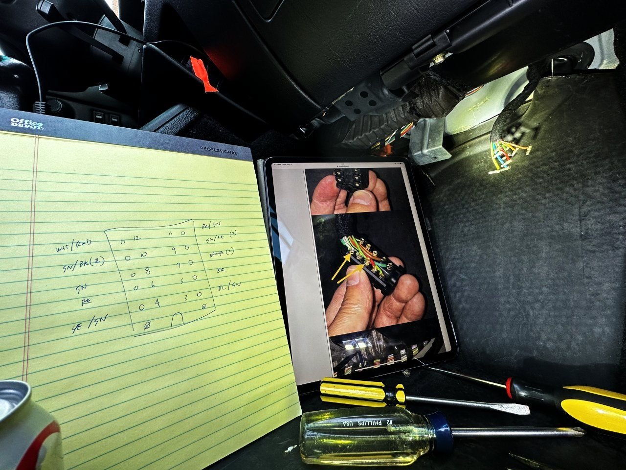
1) After all the wires came loose, I used a diagram and a pic on my ipad to try to figure out how to get them all back in the right spots.
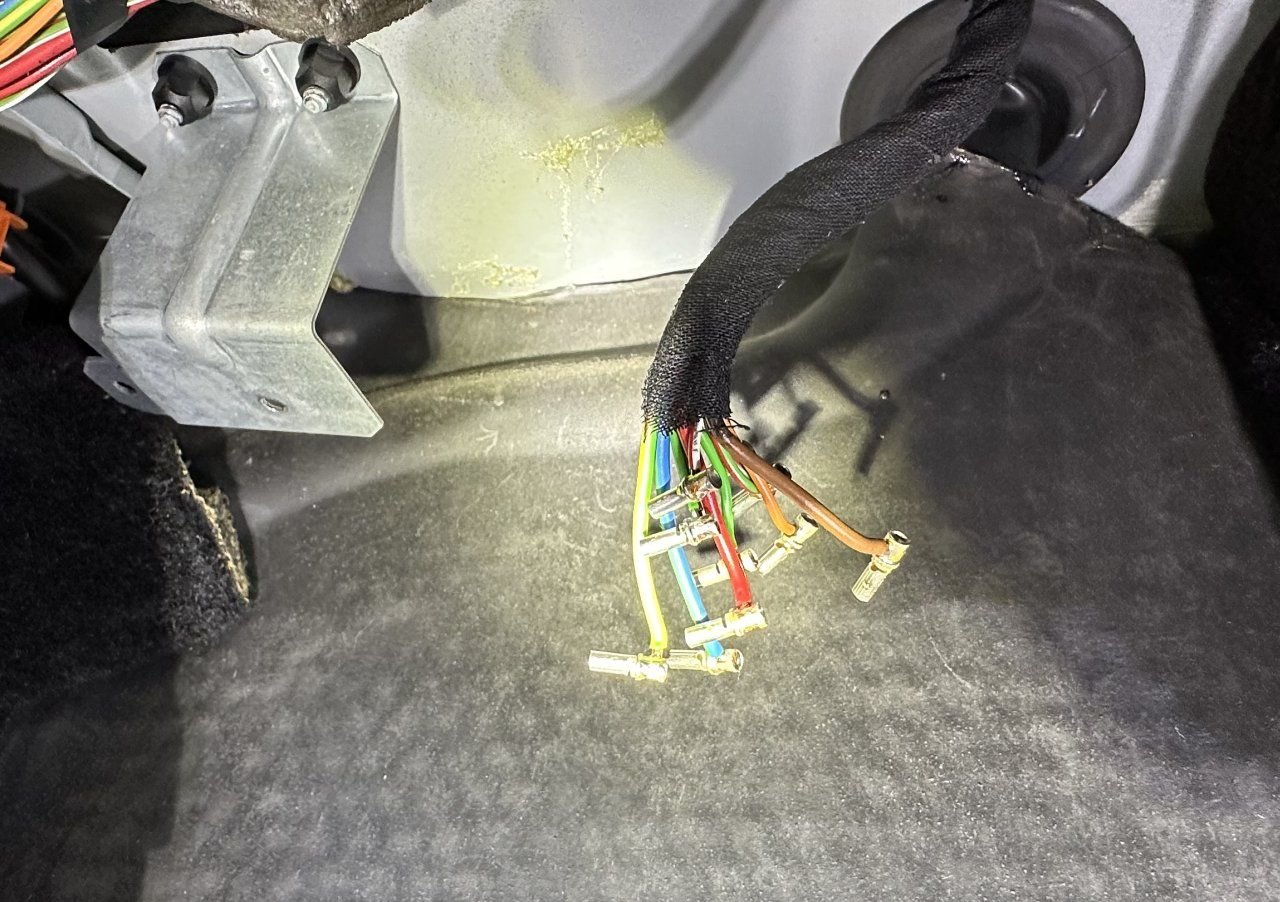
2) The loose wires. Two touched and blew a fuse.
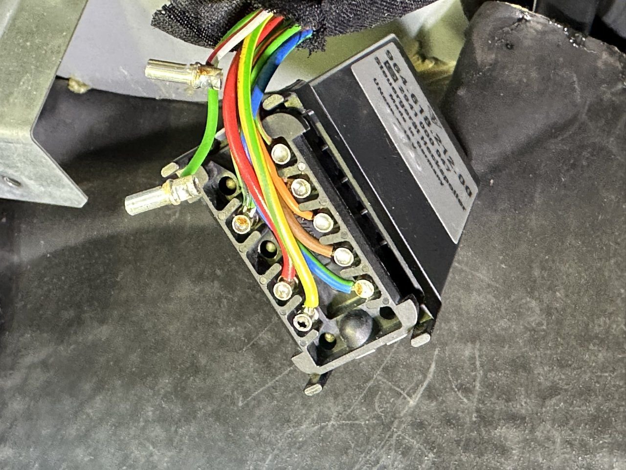
3) The wires back in the connector when plugged into the module. (You need to insulate the two removed wires, I did this after photo was taken.)
.
Last edited by centerpunch; 06-23-2023 at 11:43 AM.
Thanks for the tip about the hot wire. Which fuse blew? I think I'd rather pull the fuse than disconnect the battery because I don't want to run through the OBD2 drive cycle upon battery reconnection if I can avoid it.
Thanks for the tip about the hot wire. Which fuse blew? I think I'd rather pull the fuse than disconnect the battery because I don't want to run through the OBD2 drive cycle upon battery reconnection if I can avoid it.
Yep, like Jay said, 37.
However, I notice that 17 is also for the rear spoiler, not sure if it's live when the car is off, but it couldn't hurt to remove that one too.


 10-10-2021, 09:58 AM


