

Steering improvements? - anatomy of a tie rod inner ...
 03-04-2008, 02:36 PM
#1
Rennlist Member
Thread Starter
Recently, we debated the potential to enhance the responsivness and precision of the 993 front suspension, particularly in relation to a $$$$ GT3RS, in this thread.
The issue of firming the lower control arm bushings ( or replacing delaminated ones) is nicely addressed by the superior urethane replacements that Chris offers: as I caught mine prior to degradation, I will stay with the injected urethane described
here as long as they preform well: then, I will switch to urethane!
The inner tie rod ends were the second issue discussed ( rack mounting being the third) contributing 'softness', due to the rubber mounting of the female sleeve into the monoball housing: the most elegant solution was presented by Steve, that being the use of EVO/RS parts.
Being the cheapo, DIY type, I thought that welding a big fat washer over the front so as to attach the sleeve to the body would do the trick ..... making a DIY EVO part .
.
The more this idea matured, the less it seemed to be a good plan ..... the heat of welding would fry the rubber, resulting in off gasses which displace the argon inert gas blanket = crappy welding.
Having a sacrifical tie rod assembly, out came the sawzall - autopsy time!! The four attached pics are reasonably self explanatory ....
The female threaded coupler is rubber bonded to a steel sleeve: this sleeve is pressed into the barrel of the inner tie rod end, and secured with a roll crimp - much like a tin can. The very inner end of the female coupler is 'T' shaped, and has a void of 2.5mm in both axial directions: the coupler has some radial play as well; however, it is axial play that will deaden the response rate to steering input.
So what to do??? I haven't eliminated welding a bridge over the exposed end - but am lacking confidence of that being a valid approach. What I am currently favouring is to cross drill the barrel and female coupler in one ( or two) locations inside the reach of the outer tie rod attachment threads ..... and pinning the two together.
The M6 allan headed bolt shown ( to be a longer version) is what I now favour as a 'pin' - drill and tap M6, and thread a grade 10.3 or 12.6 M6 x 40mm allan bolt in , slopped with red loctite. Being threaded, radial play will be eliminated - so the question is, will this adequately stop axial play??
The beauty of this, provided it is a feasible idea, is that it can easily be done on the car - so toe alignment remains unchanged.
Any critique appreciated ( unless it begins with " what an asinine ....")
The issue of firming the lower control arm bushings ( or replacing delaminated ones) is nicely addressed by the superior urethane replacements that Chris offers: as I caught mine prior to degradation, I will stay with the injected urethane described
here as long as they preform well: then, I will switch to urethane!
The inner tie rod ends were the second issue discussed ( rack mounting being the third) contributing 'softness', due to the rubber mounting of the female sleeve into the monoball housing: the most elegant solution was presented by Steve, that being the use of EVO/RS parts.
Being the cheapo, DIY type, I thought that welding a big fat washer over the front so as to attach the sleeve to the body would do the trick ..... making a DIY EVO part
.The more this idea matured, the less it seemed to be a good plan ..... the heat of welding would fry the rubber, resulting in off gasses which displace the argon inert gas blanket = crappy welding.
Having a sacrifical tie rod assembly, out came the sawzall - autopsy time!!
The four attached pics are reasonably self explanatory ....The female threaded coupler is rubber bonded to a steel sleeve: this sleeve is pressed into the barrel of the inner tie rod end, and secured with a roll crimp - much like a tin can. The very inner end of the female coupler is 'T' shaped, and has a void of 2.5mm in both axial directions: the coupler has some radial play as well; however, it is axial play that will deaden the response rate to steering input.
So what to do??? I haven't eliminated welding a bridge over the exposed end - but am lacking confidence of that being a valid approach. What I am currently favouring is to cross drill the barrel and female coupler in one ( or two) locations inside the reach of the outer tie rod attachment threads ..... and pinning the two together.
The M6 allan headed bolt shown ( to be a longer version) is what I now favour as a 'pin' - drill and tap M6, and thread a grade 10.3 or 12.6 M6 x 40mm allan bolt in , slopped with red loctite. Being threaded, radial play will be eliminated - so the question is, will this adequately stop axial play??
The beauty of this, provided it is a feasible idea, is that it can easily be done on the car - so toe alignment remains unchanged.
Any critique appreciated ( unless it begins with " what an asinine ....")
 03-04-2008, 02:53 PM
#2
Addict
Lifetime Rennlist
Member
Lifetime Rennlist
Member
Very interesting...I think pinning the coupler in two places will pretty much eliminate all play, axial and radial. I will be following this thread with drill and tap poised, but I want to hear how steering wheel vibration is affected for street driving.
03-04-2008, 03:25 PM
#3
Burning Brakes
How much are the RS tie rod ends ? The downside is that one has to have the toe-in adjusted afterwards if the rods are changed.
I fear that a 6mm bolt could "wiggle" loose over time as the load on it probably is quite high at times ?
What about drilling a 8mm hole at the top of the "t" and fill it by welding ?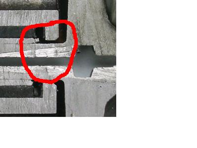
Edit: read through once again, with threading the inner the bolt wold probably hold up.
I would probably go for a weld/bolt solution myself.
Last edited by Akerlie; 03-04-2008 at 03:44 PM.
03-04-2008, 03:46 PM
#4
Drifting
What about packing the hole with JB Weld, epoxy, urethane or something similar, screwing in the tie-rod end to hydraulically press the material in and presto, no air gap.
03-04-2008, 04:17 PM
#5
Guru
Lifetime Rennlist
Member
Rennlist Small
Business Sponsor
Lifetime Rennlist
Member
Rennlist Small
Business Sponsor
Great work! I love cut-a-ways
There appears to be enough wall thickness to take a bolt of that size. However, I would fear the bolt would either loosen, wear, or oval the bores simply due to not being able to properly stretch the bolt by tightening it to some typical torque spec. Maybe a shoulder bolt could be used.
There appears to be enough wall thickness to take a bolt of that size. However, I would fear the bolt would either loosen, wear, or oval the bores simply due to not being able to properly stretch the bolt by tightening it to some typical torque spec. Maybe a shoulder bolt could be used.
03-04-2008, 05:54 PM
#6
Hi Garth, I'm no engineer, which might become immediately apparent, but having looked at your amazing pics it seems to me that if one cut off the last few millimetres of the outer tube where it curls over to hold the inner sleeve, the inner sleeve and rubber element may be withdrawn. If this can be done, an aluminium sleeve could be inserted in its place. This would require no external bolts.
I wish I had the ability to draw on the pics to illustrate my idea but being a doofus such capabilities are beyond me.
Regards
GR
I wish I had the ability to draw on the pics to illustrate my idea but being a doofus such capabilities are beyond me.
Regards
GR
Trending Topics
03-04-2008, 09:55 PM
#11
Rennlist Member
Is there some kind of liquid urethane that we could use to fill the void? Urethan would still have a little elasticity, but firm things up considerably. Possibly use a vacuum pump to help eliminate any air gaps.
I thought I saw a thread where some guys were firming up some other bushings that way.
Pete
I thought I saw a thread where some guys were firming up some other bushings that way.
Pete
03-05-2008, 04:58 PM
#13
Rennlist Member
Thread Starter
To verify how this rubber bonded sleeve functioned re. axial deflection, I inserted the half without the inner ball joint into a bench vise: with one finger pressure on the handle, the 2.5mm compression was achieved - ie., full compression at relatively modest force. As the coupler is perfectly elastic, extension would be equally easy.
So, what does that mean to steering precision? Firstly, for order of magnitude, I had noted when previously setting up the toe-in adjustment and fine tuning to absolutely center the steering wheel, 1/6 of a turn the the M14x1.5mm ( = 0.25mm of axial movement) adjusters equated to nearly 35mm movement at the steering wheel circumference.
This compression of the inner tierod rubber discussed above is 10x that ...... so the effect of a loaded suspension while cornering is bound to be noticibly non- linear in that rapid message exchange amongst eye, brain, and hands ...
You can figure out the rest: as the tie rod attaches to the aft side of the carrier, the outside wheel in a corner will load so as to compress the inner tie rod end, which has the net effect of creating toe-out wrt the intended line of steering. This effect will be reversed to a lesser extent on the inboard wheel, as it is less loaded, etc., etc.
So, I am more motivated to eliminate this axial play. To continue the anatomy, it was a simple matter to pry the two pieces apart, which indicates that the lip and groove shown take the brunt of the force, and a roll crimp added for security to keep the halves together.
The whole assembly is fabricated from ductile, mild steel - this is a place where one wants pieces to bend vs break in the worst case ( so 'stress risers' are of no concern - but weld hardening would be). The visible bending is evident here as these parts came from a damaged suspension.
Next step: I plan to fab up a jig with a centering pilot hole for the drilling, and will drill M6 in one or two locations: if I find really robust roll pins, then they may make a better mod .... ie., drill, and press them in via vise or C-clamp.
03-05-2008, 05:47 PM
#15
Hi Garth, me again, I'm interested in this idea even though I've just replaced my tie rods and thrown the old ones away.
I've fiddled with your pic to illustrate an idea, I hope you'll forgive my amuterish efforts, but having the thing in bits on your bench do you think it's doable?
Regards
GR
I've fiddled with your pic to illustrate an idea, I hope you'll forgive my amuterish efforts, but having the thing in bits on your bench do you think it's doable?
Regards
GR