When you click on links to various merchants on this site and make a purchase, this can result in this site earning a commission. Affiliate programs and affiliations include, but are not limited to, the eBay Partner Network.
I have a very annoying picture request.
two wires inside the switch housing pulled out of the proper slots, 1 green 1 black.
there are two phillips screws holding the cover panel(where the lift actuator button is located).
then there is a large plastic part with all the wires inside.
could someone take a picture of the wiring going into the large plastic part?
need a picture of the left side, where the outlet feeds into the box.
crazy as it sounds, the manual has no wiring diagram, the diagram on the back of the panel doesn't relate to the wiring in the box, and bend-pak tech support doesn't have a wiring diagram.
thanks
thanks
logistics are tough, lift is 50 miles away at the track and didn't have a camera yesterday when it broke.
seems like there were 6 wires total going into the plastic wire box, black white and 1 green.
the green, which I assume is the ground, is the problem, can't figure out where it goes.
thanks for the pics
yes much different version, but the wiring diagram still helps.
I'll drive out today and experiment trusting the source breaker to keep the pump motor safe.
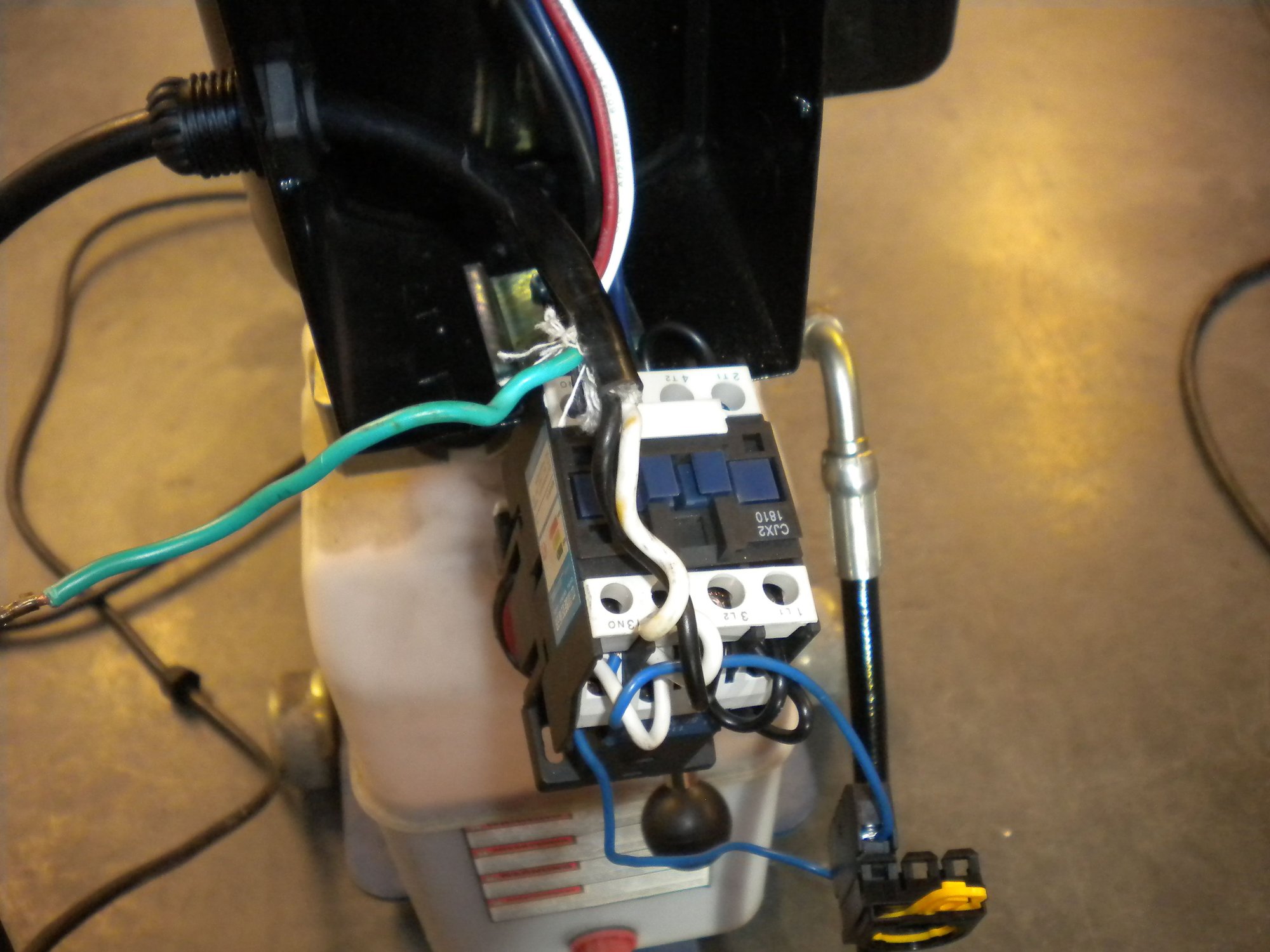
here's what the connector looks like, they change the version often.
put the black wire where it made sense, green/ground screws onto the pump housing.
still trips the breaker, could be the connector is bad.
Semi reviving this from only about a month ago. I�ve had my MD 6XP for roughly 5 years now. Today I put my Audi up on the lift in preparation for a clutch job and noticed one of the anti rotation tabs for the pin connecting the main platform to the lift arm (hydraulic side) was broken and the pin had rotated. The pin looks captured since there is a cotter pin on the other end. But wondering what the point of the anti rotation tab is then.
Anyone else had this happen on theirs?
Also wondering if your guys� lift arms bend as much as this when lifting a 3900lbs car.
Broken Tab
Other side for reference
Bending arm- straight edge across both arms for reference. I have read somewhere before bendpak mentions this is normal to a degree, but this is bordering excessive in my opinion.
I will be reaching out to Bendpak about both of these items, but wanted to gauge the forum too.
The pin looks captured since there is a cotter pin on the other end. But wondering what the point of the anti rotation tab is then.
There is a bushing in that joint. The tab is there to insure that the rotation of the joint occurs between the bushing ID and the pin OD rather than the pin rotating in the bore of the external supports - which has occurred in your case. It is something that should be repaired to maintain the longevity of the lift. There will come a time when the pin seizes to the external supports which will make servicing / repairing very challenging. While there is no impact to integrity, the sooner you repair it the better.
There is a bushing in that joint. The tab is there to insure that the rotation of the joint occurs between the bushing ID and the pin OD rather than the pin rotating in the bore of the external supports - which has occurred in your case. It is something that should be repaired to maintain the longevity of the lift. There will come a time when the pin seizes to the external supports which will make servicing / repairing very challenging. While there is no impact to integrity, the sooner you repair it the better.
Thanks for the bushing input! My reasoning for the anti rotation tab was to avoid wear on the pin, that makes perfect sense that there�s a bushing, as otherwise the rotation would just wear the pin hole instead. My main concern was safety. Having concluded (by educational reasoning) that the pin isn�t at risk of disassembling- I will look to weld the tab back in place.
here's what the connector looks like, they change the version often.
put the black wire where it made sense, green/ground screws onto the pump housing.
still trips the breaker, could be the connector is bad.
this picture is confusing...that is essentially a contactor, when you push your button to engage...you are pushing in the blue portion of the above, that complete the circuit between the two ends. Pump/motor is wired to the back side of this I presume? Since this contactor breaks both lines, hot(black)and neutral(white) in a 120v application, make sure no wires jump between the sides. Use a simple volt/ohm meter if you have one...I am confused with the number of jumpers in the picture.
Disconnect the pump side, leave alone the line(cord) side, and plug in...if the breaker trips again, then you have a wiring problem on your input side.
sorry, should have updated this.
turned out to be two things at the same time.
wires got loose and the new track management reduced load/power or something to the track garages.
so wires back in, pump works fine everywhere but the track garage.
electric shop explained I need to hook up a multimeter to the white and black, get standard 120, then press the power button.
voltage drops to 90 or something, happens very quick. but it also pops the gfi and circuit breaker.
track management repair guys said nope, problem is your pump, doesn't matter that it works every where else.
but by then it made no difference, race season is on hold so all my tools and lift are at home where the pump works perfectly.
If the electrical system at the track garage is dropping the voltage to 90 volts when a simple hydraulic pump is activated...the electrical system in the garage is somehow over taxed. Perhaps the incoming voltage somehow changed, or they recently replaced a transformer and didn’t test the output voltage. Transformers have multiple taps to adjust the output voltage up/down a few percent to compensate for input fluctuations. Voltage that low will screw with everything...what the hell is it doing with 208v single and 3 phase loads. Voltage goes down, current draw goes up. Old GFCI’s didn’t much like motors either.
If the pump works everywhere but the garage, the problem ain’t with the pump. When it becomes track time again, if that low voltage issue isn’t corrected...don’t plug anything valuable in.


 03-09-2020, 05:47 PM