When you click on links to various merchants on this site and make a purchase, this can result in this site earning a commission. Affiliate programs and affiliations include, but are not limited to, the eBay Partner Network.
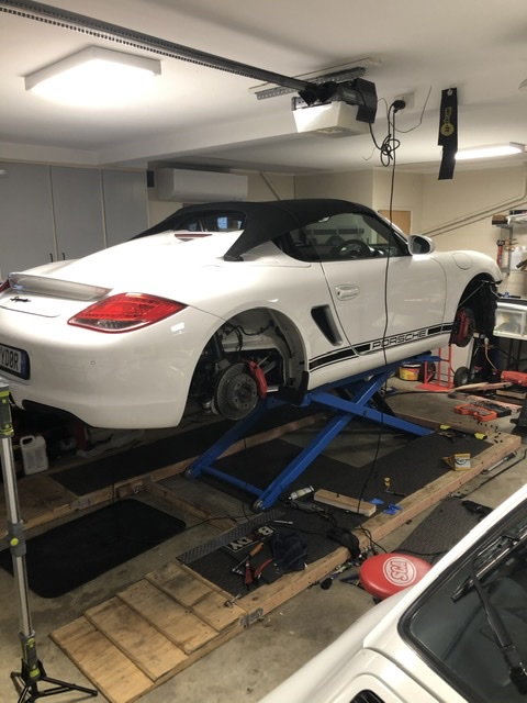
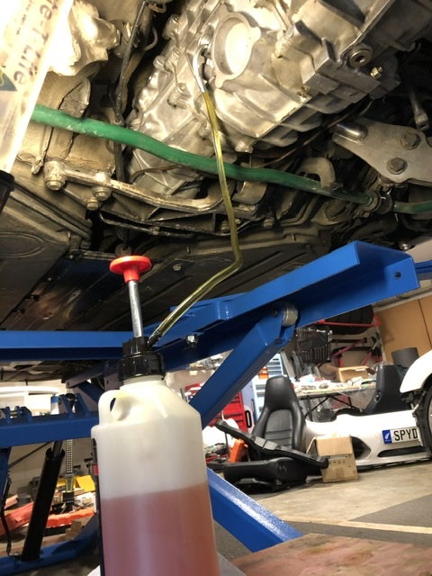
Mine is the Chinese made lift without the bar. I note it has a heavier centre box section than the Bendpak one. That may be an area to reinforce on the Bendpak. I have not detected any lateral movement on mine. I was under there doing the transmission oil on the weekend and had the Spyder up yesterday.
Not sure you can tell what is heaver by pics, but I can say I've had no issues with my BP, and have never had any lateral movement.
Bendpak have a whole section on what makes their product more robust than the Chinese made ones so I can see the design differences.
My one has a larger box section connecting the two bars and has no other bars connecting those two. This means I can drop a C4 engine and transmission without having to put the car on the other way or cut the lift to make it work. I�m simply commenting that mine has no lateral movement as designed and I can see that the Bendpak may not be as safe if cut.
Since my BP has 3 cross section spars vs the 1 on yours, I'm not concerned about which is "bigger", no if the subject mod is done. I'd rather have the spars spread out along the length, if truth be told than one in the center. I've dropped motors and transaxles on several 911's and did a bit of work on my old 928 without issue.
Since my BP has 3 cross section spars vs the 1 on yours, I'm not concerned about which is "bigger", no if the subject mod is done. I'd rather have the spars spread out along the length, if truth be told than one in the center. I've dropped motors and transaxles on several 911's and did a bit of work on my old 928 without issue.
My lift is for my personal use and it's me putting my body and property on the line with each use. I can't abrogate the responsibility for my safety to an online forum but as always there's some gems from reading wider thoughts e.g. the COG discussion. To each their own.
Again, multiple crosses spread along the length seems more robust in my mind, or at least as equal as yours with the single, albeit larger, crossover.
I too put my life �at risk� when I get under it, and do not have a death wish. I�m going to keep the counter comments up to each one you make that puts forth any shred of question on the BP design, as I don�t want someone searching on Bendpaks to see your postings and have any reservations on quality or durability.
Sorry, but my interpretation is that you�re making misinformed statements when you make comments such as �Bendpak should reconsider the design, my Chinese unit has a bigger box section�.
Their products have passed the scrutiny of many users, for many years; private and commercial. Not just on crossbeam design, but locking mechanisms, etc. If you�re happy with yours, great. But don�t put out the idea that the BP design may be dangerous or weak, based on your opinion of its design. Until you put up empirical data that shows yours has a superior failure point, it�s just conjecture.
I�ve got no affiliation with Bendpak, but I�ve been a happy customer for over 15 years that has had the same lift in 3 states, 5 houses and moved thousands of miles in the process. I�ve dropped drivetrains on 3 air-coooled Porsches, and had probably 12 cars total up on the lift over the years. So, I have some experience to base my statements on.
Enjoy yours.
Originally Posted by John McM
My lift is for my personal use and it's me putting my body and property on the line with each use. I can't abrogate the responsibility for my safety to an online forum but as always there's some gems from reading wider thoughts e.g. the COG discussion. To each their own.
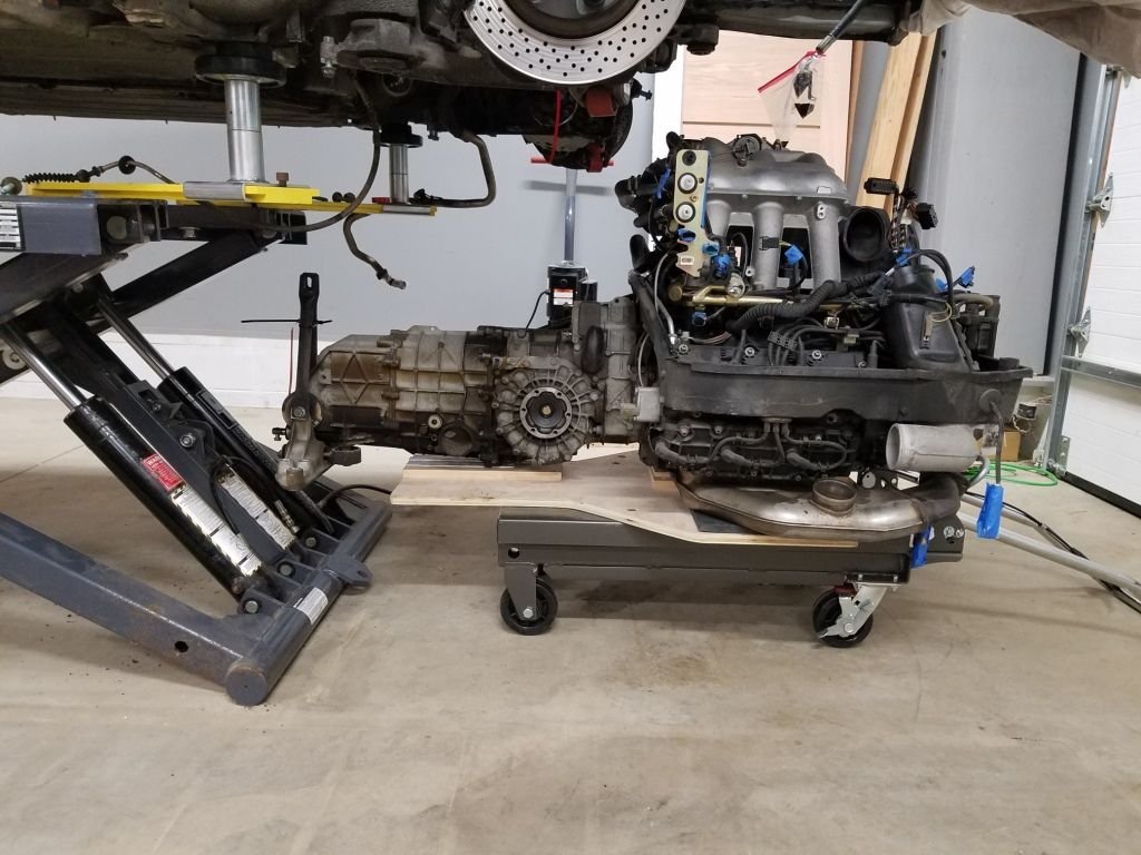
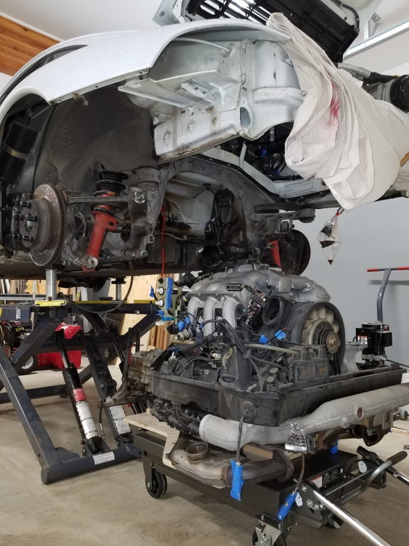
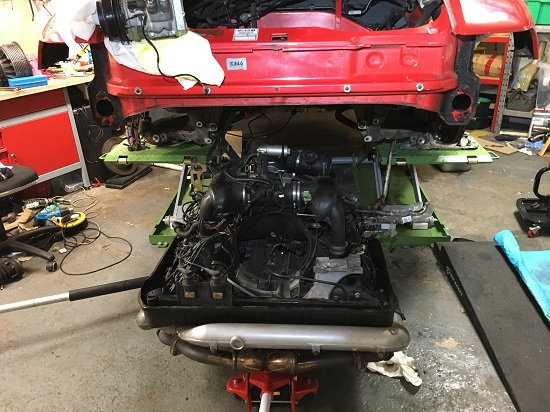
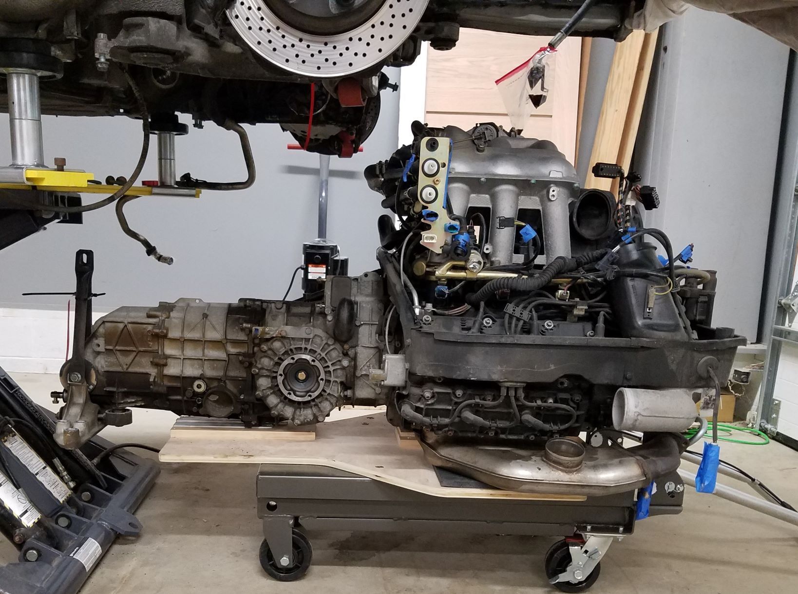
Last night the engine and trans dropped down nicely. One of my helpers said it was the easiest engine out he'd done, although to be fair, I'd removed a lot of stuff this past week which gave a lot of clearance around most things. We broke a grommet and small plastic clip so the damage was limited although I've not checked Porsche grommet pricing lately, I may regret ripping that one....
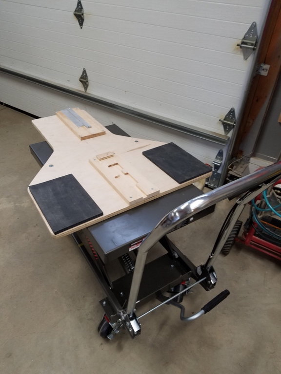
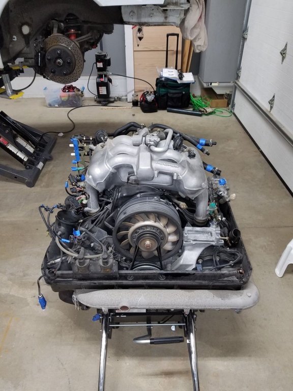
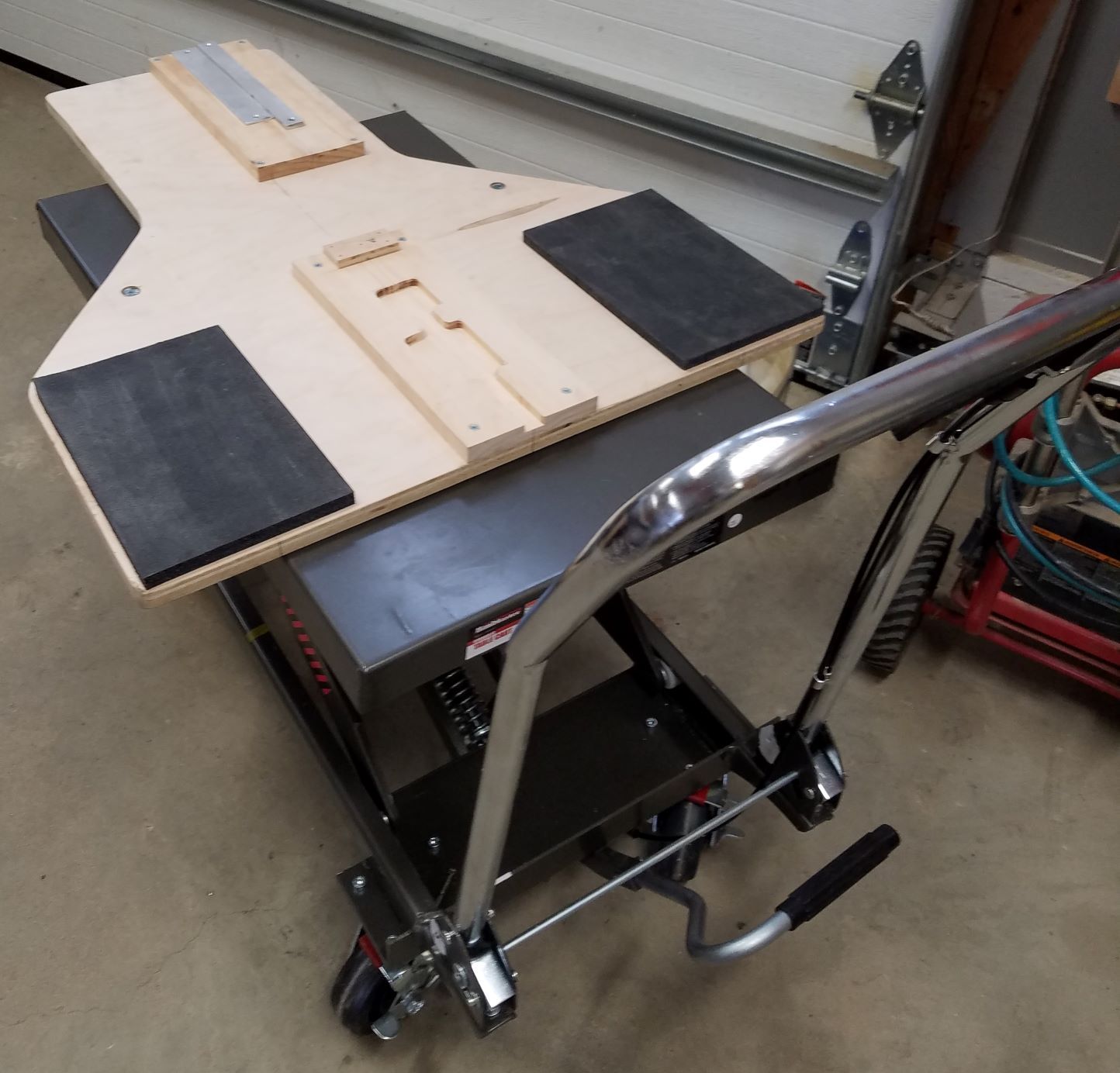
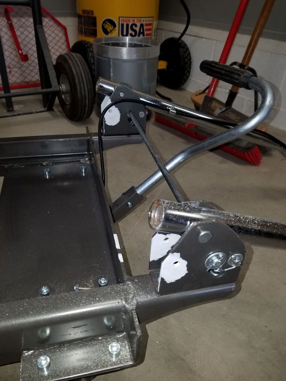
Made a platform/cradle for the 1000lb Harbor Freight lift table:
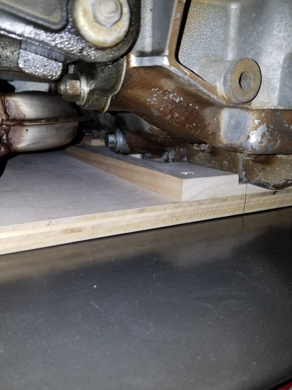
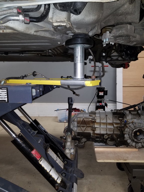
Touch-off point bottom rear of engine block:
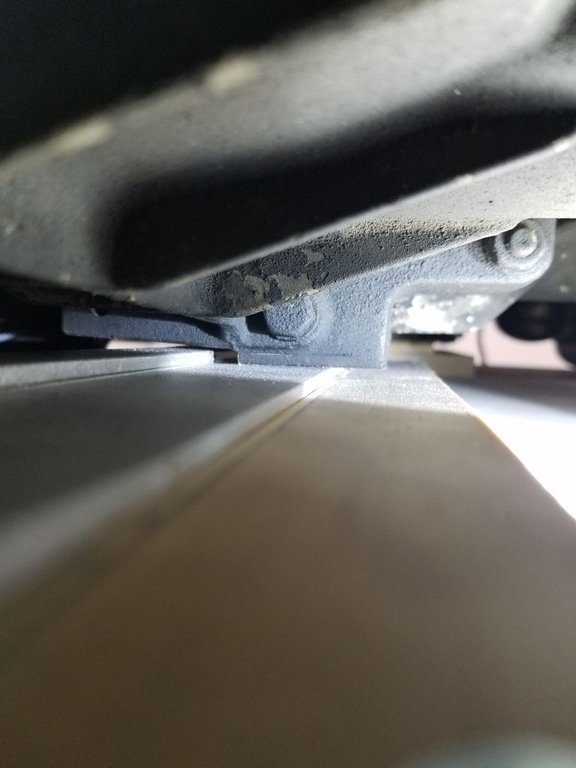
Touch-off point on trans, just forward of the drain plug:
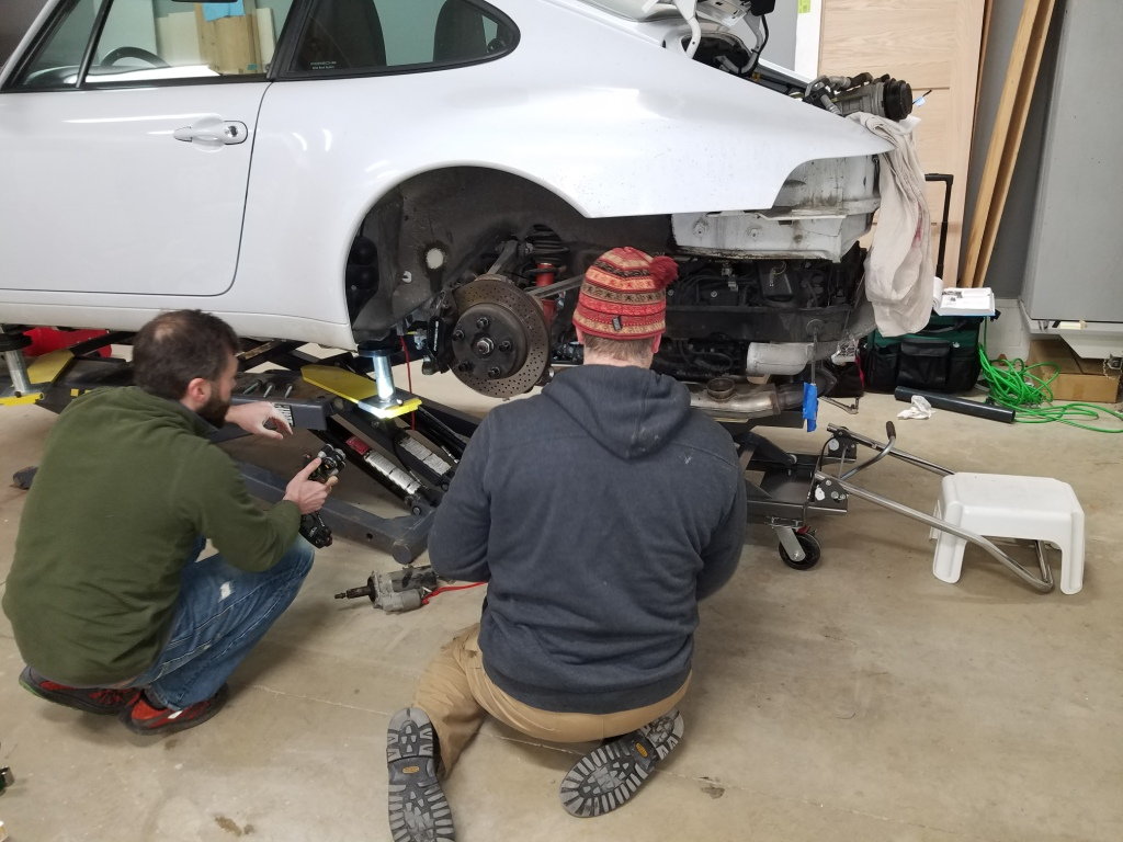
Couple of spotters helping out:
For the first part, I decided to lower the HF table rather than lift the Bendpak - the movement control was a lot smoother.
Once the engine + trans were low enough and everything had clearance all around, I raised the Bendpak.
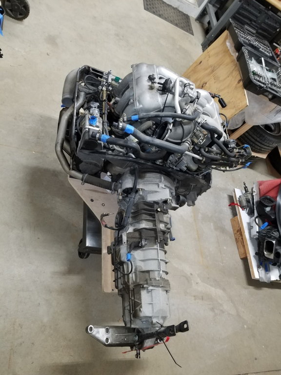
18:30 we had total separation!
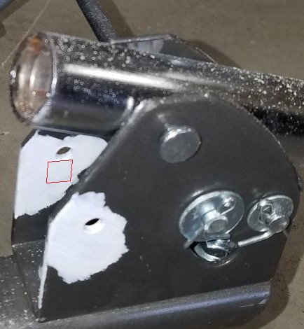
I also modified the table handle so it could fold away from the table to clear the heater tube running across the rear of the engine (as it comes, the handle only folds into the table, for storage). Just a couple of removable stainless pins in place of the welded handle stop-bars:
Having the lift made the whole stripdown process a lot more knee/back/sanity friendly. And with the clearance under the lift down the middle, I could easily get in to switch out the gear lever mechanism - got some goodies to replace and upgrade all that
I like this lift a lot.
Cheers
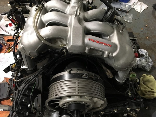
Very nicely made table. I dropped mine last winter using very similar system. Could you please publish table dimensions mine was a bit more miss than hit and misjudjed the balance point I also tore a grommet and cable tie. I originally used the cradle from Pelican with a trolly jack but it was very unstable. When I did the refit I used a transmission jack with table. Notice Vram was added.
Just a thought that validates making �the mod� to the Bendpak to allow easier trans clearance: when you turn the lift 180 deg and put the lift cylinders toward the rear of the car, they are exposed to damage should something happen bringing the assembly down, or even dropping a tool on to the polished metal. Maybe minimal risk, but risk nonetheless in my mind.
Could you please publish table dimensions. Notice Vram was added.
Thanks Endoman. I will post a dimensioned drawing up here.
I remember reading about your vram conversion - nice job indeed.
BTW, I am originally from Burnley
Originally Posted by Ed Hughes
Just a thought that validates making �the mod� to the Bendpak to allow easier trans clearance: when you turn the lift 180 deg and put the lift cylinders toward the rear of the car, they are exposed to damage should something happen bringing the assembly down, or even dropping a tool on to the polished metal. Maybe minimal risk, but risk nonetheless in my mind.
Yup, that was considered and it is a valid concern. I'm not getting into the debate on cutting, I just preferred not to.
Originally Posted by 95_993
^^^Awesome job dropping the motor. ^^^
I dig the platform u made
Thanks a lot! I got your PM, I will post table dims. Good luck yourself!
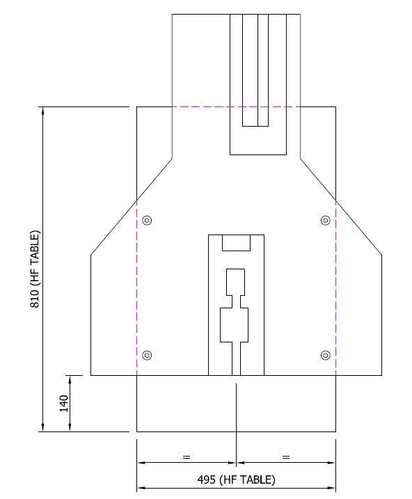
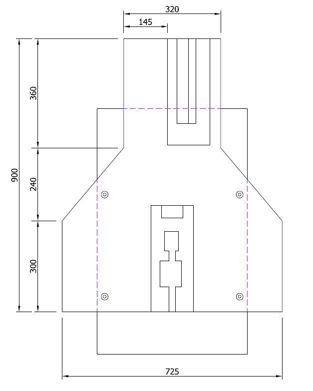
Here are some platform/cradle dims to suit the Harbor Freight 1000lb hydraulic lift table. Obviously, please make your own assessment on robustness and stability: The engine + trans weigh around 500lbs.
Apologies in advance, dimensions are in mm cos I'm rubbish at working in English/Imperial (irony....):
I needed the table to go fairly deep under the engine (towards the front of the car) - deep enough that the heater tube (think that is what is called - cast aluminum tube running across top rear of engine) would hit the HF table handle if the handle was locked in the upright position.
As delivered, the handle folds into the table for storage - not away from the table. I've seen some unbolt the handle (4 bolts) and lay on the floor during the drop.
Instead, I ground off the two welded square bars in front of the handle (red square below) that prevent it folding backwards, then drilled two holes to suit stainless M6 caphead bolts (pins would work).
So now it can lock vertically or fold rearwards (remove 2x M6 bolts) or fold forwards (release the HF mechanism):
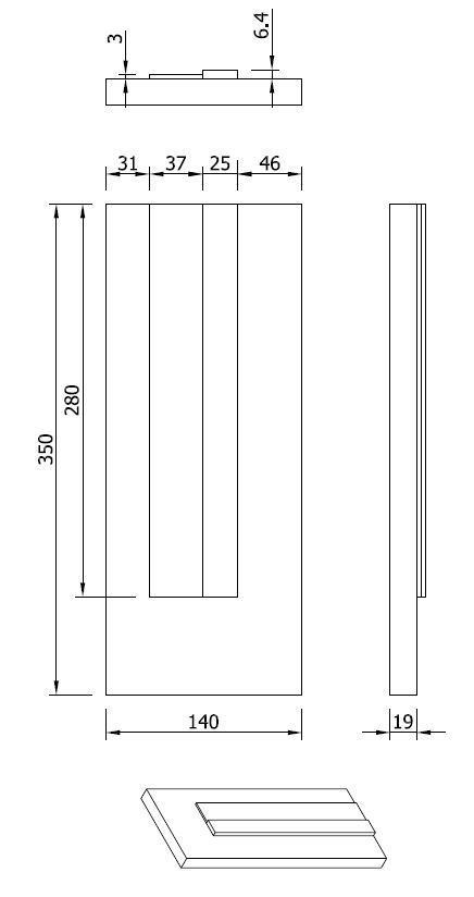
For the cradle I used 3/4" (19mm ) plywood.
Position on the HF Table is like this:
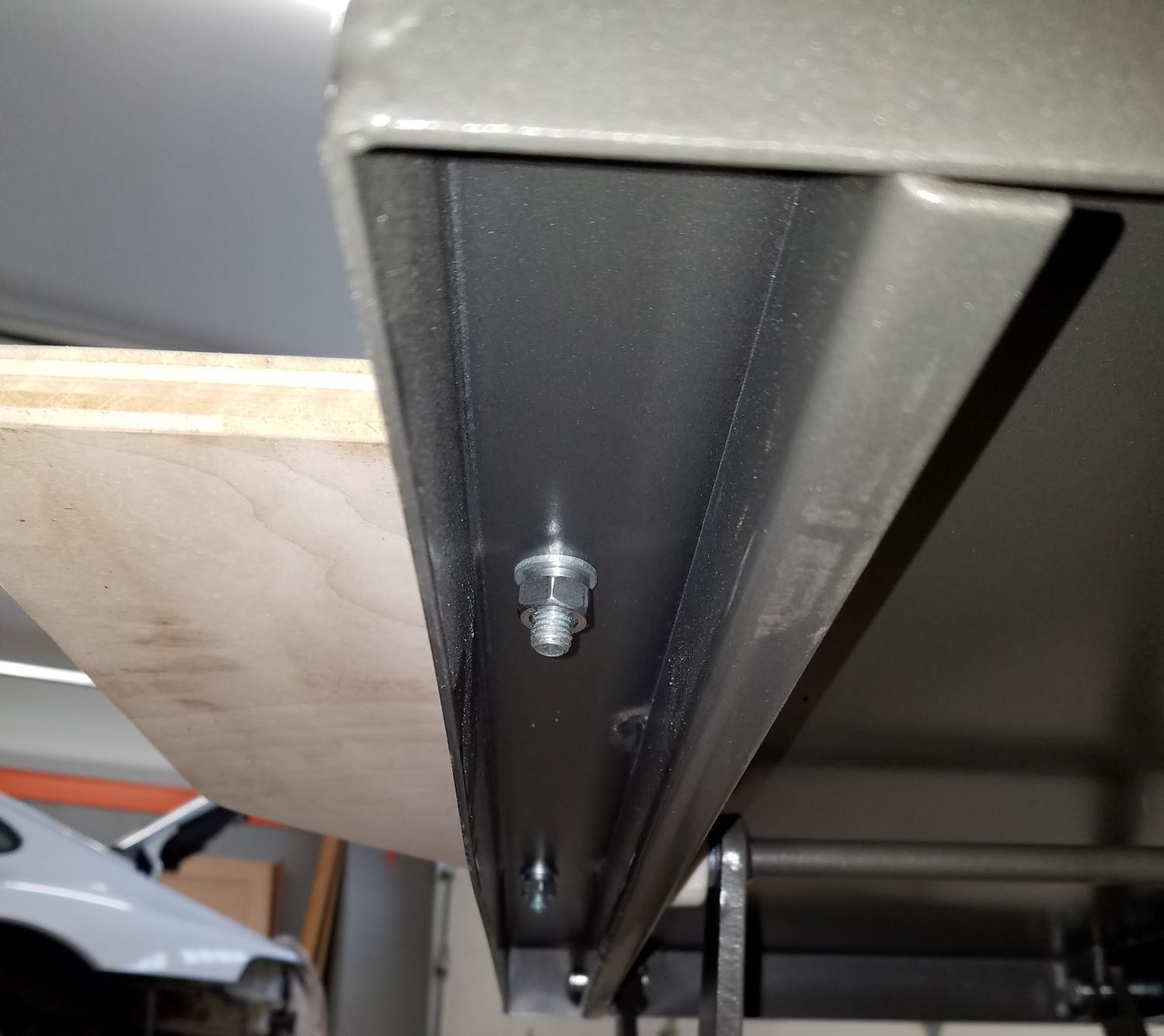
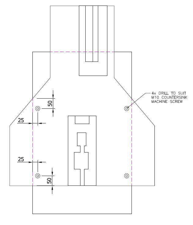
I used 4x stainless M10 countersink machine screws that were located to sit inside the rail areas under the HF table. Here they do not interfere with any table movement etc.
Used M10 washers, spring washers and nuts:
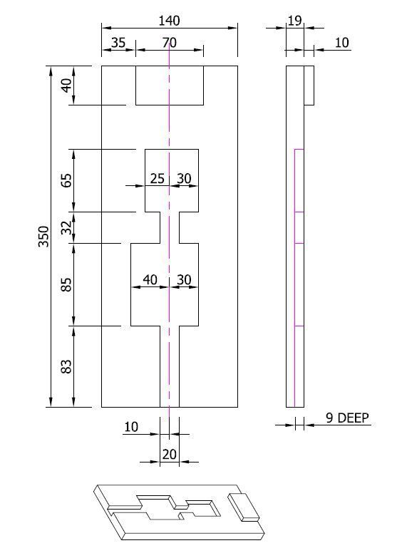
For the engine touch-off point I used 19mm thick wood with the profile routed out 9mm deep.
I wanted this touch point to take most of the weight of the assembly, rather than the two headers on either side that I left connected for the drop - but the headers also do take some weight and provide the balance - so they sit on some foam pads glued to the plywood:
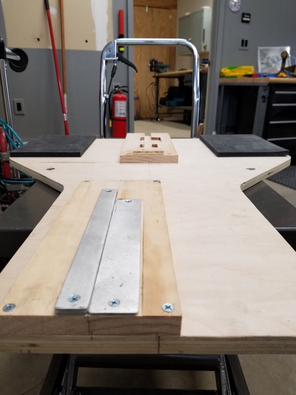
For the transmission touch-off point I used 19mm thick wood and some old aluminum stock I had. The idea (may not work) is to give a slicker surface for sliding when I split the trans from the engine.
For the 3mm thick aluminum section I actually used 1/8" (3.2mm) thick and then routed the wood to sink the aluminum down a little (0.2mm) to give only 3mm protrusion. For the 6.4mm thick section that was just 2x 1/8" thick stock. Probably doesn't need to be that specific...
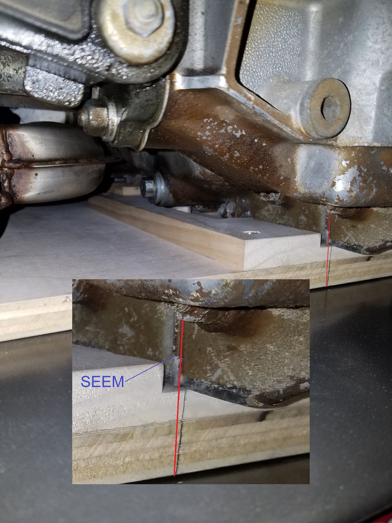
When the time comes, you align the rear face of the plywood with the vertical seam (not 'seem' ) on the bottom of the engine block. On my car, all other points on the cradle then lined up.


 01-27-2020 | 02:11 PM