hello folks I need some guidance on my left mix flap as it is not working. I luckily have a PST2 tester which can assist me in trying to fault find. The PST2 tester through the drive links checked every servo and fans etc all where fine except the passenger lower foot well flap which did not move or work.
I removed the lower mix flap and took it apart and cleaned it and bent the pins back on the potentiometer etc but still no good. I bench tested the servo by applying 12 volts positive to pin 5 and negative to pin 4 and the servo worked for like two seconds then I swapped the polarity on pins 4,5 and it moved again for like 2 seconds.
The problem is when hooked up to the car it does not work. I decided to pull the servo and look at what voltages I was getting at the pins and these where as follows:
pin 1 is ground all the time
pin 2 is 0 volts
Pin 3 is 0 volts
Pin 4 is live all the time showing 11.68 volts (ignition had been on for a while)
Pin 5 is ground but when I try to get the PST2 tester to activate this lower flap to see if it is getting a signal then this pin goes Live and shows 11.68 Volts. If I press the stop button on PST2 tester then the pin goes back to ground.
I did find a broken track in the servo when I stripped it down I feel I might have repaired it incorrectly pic will attached if I can do it from my phone.
any input would be helpful I am browsing previous posts to see if I can learn anything and see what I am doing wrong.
Can be the burn marks or the motor in the servo pulling too much current and the CCU being unhappy with this.
Luckily I stumbled onto a company that you can order a rebuild kit from or simply ship you failed servos to who will rebuild them with new internal parts as needed: http://www.partisan-autoteile.de.
You should be getting +5v on pin2. It is supplied by CCU pin G13, and is used for servo position feedback.
The track that you strapped supplies +12/GND to motor. I would speculate that it probably "burnt" due to excessive current. Since the motor works fine on the bench, did you check the flap is moving freely, e.g. does not jam ?
A common case of a worn-out and short-circuited servo motor, causing the PCB track to blow. The servo needs to be changed or refurbished, the motor could work right now, but will short again.
Sometimes such a fault also kills the CCU output, but this can also be repaired.
I guess I will need to pull the CCU and see what is going on with the output pins. I earlier today sourced a 964 servo and bench tested that by applying 12 v to pins 4-5. It worked fine on he bench. On connecting to the car it did not work.
The flap is not stuck I checked this. I think the outputs for left flap motor have blown from CCU. Not good news.
I forgot to mention but not sure how relevant it is. The functionality of the CCU WORKS on every other function when testing with PST2 tester. The only issue is the A/C on the car has been removed no A/C fan/rad pipes or a/c pump all this has been removed.
ok I am not sure but reading Tore's extensive write up on his website about CCU I think I might need to buy TCA 2465 servo driver chip and solder this into the PCB. I just need to find out do I need two of these TCA 2465 chips to replace IC11 and IC12 on the CCU PCB? hopefully this will repair my CCU I am hoping when I pull CCU it is just a broken wire that is causing the issue as it will be simpler then de-soldering and re soldering new chips on PCB.
or I could just be lazy and leave the actuator disconnected from the left side and cook up some sort of mechanical lever mechanism to move this flap manually when the need arises.
It is difficult to measure the CCU outputs, and you can easily be fooled into thinking it is defective.
An output will be disabled if the CCU does not get the correct position change response from a servo. After a reset, (CCU shutdown after 20 minutes with ignition off or quick battery disconnect) the CCU will try to move the servos if needed. If it does not move as it is supposed to do, it will be shut down within a second. The output will then be disabled until the next reset.
The invoked OBD Drive Link test does not rely on position feedback, so it may be used to check the servo outputs or for any adjustment of the mechanical position of the servo arm. If the servo moves when using the Drive link function, the CCU is OK.
Thank you for the input Tore much appreciated it helps to know that the CCU automatically locks out certain outputs if the CCU does not see the correct position change from the servo. I think I made a mistake in trying to use a 964 servo as the part numbers are different plus the rotation on a 964 servo is 130 degrees while the 993 is 60 degrees hence although they look similar the movement range is more on the 964 hence maybe CCU going to lockout on that servo due to incorrect movement detected. The annoying thing is with this 964 servo connected to the car, the PST2 tester in the drive links menu would not move the Left mix flap (964 servo) the bar stayed at 0% however when I try the right mix flap the bar can be seen moving from 0% to 100% and I can hear the flap moving as well in the cabin area.
I think the only sure way to rule out servo and maybe move on to thinking it is CCU would be to pull the drivers working servo and place it in passenger side and swap the passenger into the drivers and see if the fault is carried across.
Did you check why you don't get 5v on pin 2 of the servo?
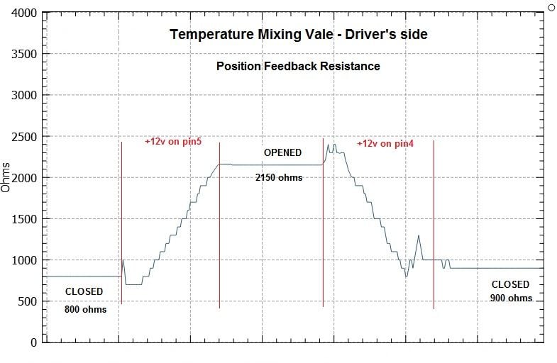
This is a typical ohm profile you should get from a servo.
Note: the resistance when closed should be lower than 800ohms as in graph, but that what i measured on mine.
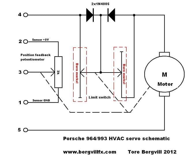
The feedback potentiometer is not the problem here, it is the PCB-based end-switch arrangement that fails due to excessive current. In this particular case, even a copper PCB track has blown.
By the way, this is a 2 kiloohm potentiometer, and the reading should be from 0 to 2 kiloohm, depending on the output arm position.
Thank you for the input Tore much appreciated it helps to know that the CCU automatically locks out certain outputs if the CCU does not see the correct position change from the servo. I think I made a mistake in trying to use a 964 servo as the part numbers are different plus the rotation on a 964 servo is 130 degrees while the 993 is 60 degrees hence although they look similar the movement range is more on the 964 hence maybe CCU going to lockout on that servo due to incorrect movement detected. The annoying thing is with this 964 servo connected to the car, the PST2 tester in the drive links menu would not move the Left mix flap (964 servo) the bar stayed at 0% however when I try the right mix flap the bar can be seen moving from 0% to 100% and I can hear the flap moving as well in the cabin area.
I think the only sure way to rule out servo and maybe move on to thinking it is CCU would be to pull the drivers working servo and place it in passenger side and swap the passenger into the drivers and see if the fault is carried across.
It's very simple to test the drivers once you open the CCU and use an oscilloscope, or a meter, to determine a bad driver.
The driver must be either pulled to ground or 12V with a load resistor (100 ohms) to fully test each of the driver's two outputs.
Slideshow: Long before engineering consulting became trendy, Porsche was quietly helping other automakers build everything from supercars to economy hatchbacks.
Slideshow: Some brands build cars. Porsche builds traditions, obsessions, and a few habits that stopped making sense decades ago but somehow became part of the charm.
Slideshow: A small Polish tuner has reimagined the Porsche 911 Slantnose for the modern era, blending 1980s nostalgia with widebody tuning culture and serious performance upgrades.
Slideshow: Porsche has created a Japan-only 911 GT3 Artisan Edition that blends track-ready hardware with design cues inspired by traditional Japanese craftsmanship.
Slideshow: Porsche's latest electric Cayenne Coupe blends dramatic styling with supercar acceleration, turning the brand's midsize SUV into a 1,139-horsepower flagship.