When you click on links to various merchants on this site and make a purchase, this can result in this site earning a commission. Affiliate programs and affiliations include, but are not limited to, the eBay Partner Network.
Thank you to everyone who contributed towards helping me solve this issue. I have sprained my left shoulder or am suffering from a trapped nerve very painful causing limited movement of my left arm so I cannot get to my garage and work on the car sadly.
I however was looking at the comments and will firstly try just switching motors across and see if fault jumps from one side to the other this will help me rule out wiring and CCU. Then I guess I will bite the bullet and buy another servo probably will go with the new improved version with the gold plated contacts from the Partisan link which was given earlier.
In the mean time I was wondering if some one had previously opened up the loom bunch connector plug going to the servo and messed about with wiring pins and their allocated locations. I have not got the wiring diagram for pin outs and zooming in on Tore's PDF it gets blurred so I tried using a porsche 964 diagram. (not sure if they are the same) maybe some one can help with that as well please.
I checked 993 according to Tore's diagram and they are as follows I think. (blurry might be wrong)
left motor
pin 1 green/white
2 brown/blue
3 green
4 brown/green maybe blue/green
5 yellow/green
however for the 965 it is different I would have assumed it would have been same ? the reason I am jumping to 965 diagram is because I had a workshop copy burnt on CD lying about and I decided to look to CCU for that hoping it was the same but the wiring is different.
965 ccu
965 CCU pin 1 is green/white for both servo's I know call me stupid for looking at a wiring diagram for a totally different car lol. I assumed they would be the same but I guess I am wrong.
okay still no where near fixing this issue. I went into the garage with my strained shoulder as it was bugging me and I needed to have a little fettle with the car. As agreed I swapped the Servo's over the non working one from passenger side to drivers side and vice versa.
I was hoping now the fault would have been carried across however this was not the case. The motor I strapped soldered a wire to on the PCB is working on the drivers side and the previously working servo on the drivers side is not working on the passenger side.
I now know both my servo's are fine the problem lies with the wiring loom or the CCU. I checked the voltage on Pin 2 and it was zero so I checked the voltage on PIN 1 and it was 5 volts so I opened up the plug and moved pin 1 to pin 2 slot and moved the original pin 2 to pin 1 does this make sense? ( my car is a RHD UK car) so now on the Left servo motor which is still not working I am now getting 5 volts on pin 2 is this correct ?
to recap my wiring colours are as follows on left servo motor
pin 1 is now Brown/Blue
pin 2 is now Green/White
pin 3 is Green
pin 4 is Blue/Green
pin 5 is Yellow/Green
I originally had pin 1 Green/White and pin 2 is Brown/Blue. The remaining pins I have not messed with.
actually now that I am sitting in front of lap top and looking at Tore's copy of wiring diagram I should revert the left side wiring back to how it was originally meaning Pin 1 should be Green/White and pin 2 should be Brown/Blue and look into why Pin 1 is showing 5 Volts. and why Pin 2 is zero volts. I hate wiring problems lol. I think I will have to check the pins on CCU and make sure these wires are going to the correct pin outs.
It's never a good idea to swap wires without understanding the root cause as to why they need to be swapped.
At this stage, i would disconnect the 5 servos and the CCU from the loom and test the loom for short/disconnection. That's 17 wires to test: 3 per servo (2 for motor, 1 for feedback) x 5 + 2 for all 5 servos for +5v and sensor ground.
OK I had a chance to do some more tinkering today and these are my findings as follows. Wiring all back to how it should be in the bunch plugs etc. I pulled the CCU and pushed a tester wire into certain pins on the K plug (the 25 pin one)
I tested K18 first yellow/green wire which goes to pin 5 on the left Servo mix flap, this showed +11 V when tested to switched on position with PST2 then when I clicked off with PST2 the voltage went to 0.7V so this is okay.
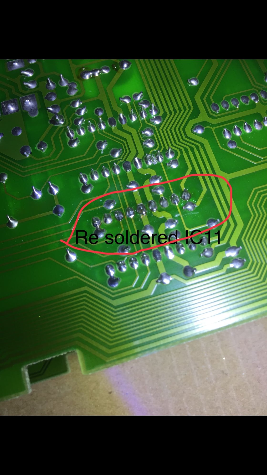
The second output from CCU I tested was K5 Blue/Green wire which goes to pin 4 on left hand side servo mix flap. This when switched on with PST2 it went to 12V not 11V secondly when I used the command to switch off the output to K5 it did not work it remained at +12V I believe this indicates I have a problem with TCA2465 and the one I need to replace is IC11 ?
to do some further checks I checked CCU output K17 (Right servo open flap command) This output when tested did go to +12V as well not 11V which was a bit strange and when I commanded it to switch off as close Servo it did however go to 0.7V
I finally decided to check K19 output and this delivered +11V when I closed footwell flaps.
I am inclined to lean towards IC11 output driver needs changing my question is this " when I open CCU the boards are sandwiched together which one is IC11 and the second question is how many solder joints do I need to disturb to open the sandwich so I can easily de solder the IC11 and resolder a replacement ?
I am hoping to this in house lol I have done some basic solder work before but then again I might use the car stereo shop not far from me who are always soldering PCB's on car audio head units.
Is it correct that my IC11 chip can go faulty and still K17 output works albeit at 12V and K5 just sits at 12V all the time ?
a lot of this diagnoses would not have been easily done with out Tore's excellent write up on his web page.
CBR786. Friends that know me here will likely laugh a little at this comment, BUT coming from someone who does 99% of all my own work on my 993, takes great satisfaction in 'fixing' something that is broke and not spending the $$ either not paying stealership rates or repairing the part; as you are attempting her, there is a time and a place to just go buy the part and be done with it lol! As much as I appreciate the fortitude you display here, why not just spend the either $250 for a rebuilt one, or $350-$400 for a new one and be done with it? A good used one maybe even half that? I am not judging you, but I've SO been down this rabbit hole you are in here and if I can offer any advice at this point is to just raise that white flag now brother! I'm sure you've seen this site that repairs these. Just in case: http://www.partisan-autoteile.de/epa...ellmotoren_993
Impressive electrical diagnosing skills BTW!
JIB I know where you are coming from and no offence taken lol. I just do not wish to buy a servo unit when it is something else that is faulty. I ruled out the servo units being faulty by doing a swap from offside to nearside and vice versa and the fault did not jump sides. So I know both servo's are good. The issue is with the CCU and these are �1000 used and new probably much more if available. The faulty part on the PCB is peanuts compared to the price of the CCU. I am not being cheap but the car is not being used and I have the use of the 964 to get my Porsche fix lol.
I do not mind tinkering in fact I find it enjoyable especially on the P cars. I know 9 solder joints will hold the TCA 2465 to the PCB and I am happy to desolder and replace the TCA and resolder these 9 legs lol. I have not stripped the CCU down yet it might be obvious once I do this and the IC11 might be labeled on the PCB. I know where the IC's are 4 in total I do not know which is IC11?
I only update on here so that once I fixed the issue it might help others who are in a similar boat. I do not wish to simply end the thread on did he fix it ? also if I type my findings hopefully it will go in some way helping another user with similar problems lol. I still am considering buying another servo unit any way as I feel the passenger (left One) had too much current draw and this in turn caused the output driver to malfunction.
feeling like a fool lol
I think I fixed my problem giving updates so any one else in similar predicament does not go round in circles or waste money ! Luckily I am doing stuff in house this is why costs are low or it is taking so long ha ha.
I opened up CCU cleaned the sensor that lives in the front panel easy enough was dusty so used a q tip to pull away dust and electrical cleaner. moving on I removed IC11 TCA and re-soldered another and tested the unit big let down no fix of issue.
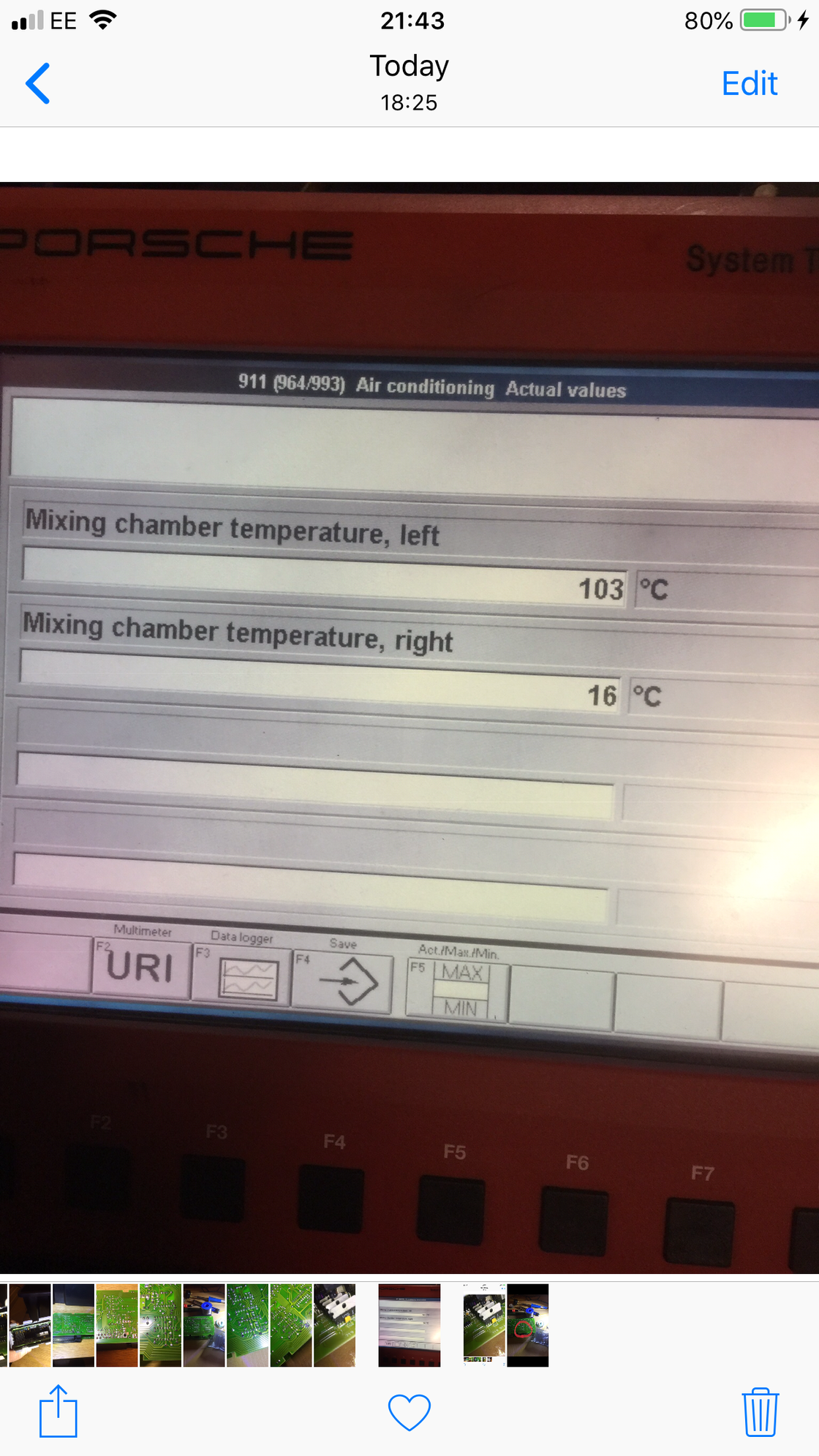
I decided to plug my PST2 tester again and look at the mixing chamber temperature sensors and I feel here is where my problem is. I am still not sure so putting it out here can the temperature sensor cause mixing servo not to open and stay closed all the time?
how hard to change temperature sensor looks awkward as A/C pipes go across the suitcase behind front screen in luggage area. might need to do some more research.
obligatory pics provided in case some one thinks I am trolling lol.
Your mixer chamber sensor reading of 103�C in a cold car will definitely cause problems with the mixer flap operation. It is not hard to change the sensor, it is a normal 10k NTC thermistor. This thread previously had some pics of the sensor, I am not sure why they are gone.
Cheers,
Tore
Fixed it I ordered another thermistor but as I was putting everything back to how it was I decided to pull the temperature sensor to get it ready for soldering in new thermistor. Once opened I heated it up with hot air gun and had my PST2 tester connected in real time to see if it registered temperature increase it shot up to 153 I think then I let it cool down the t quickly went to 12 degrees so then tested left mix flap it worked. I will test again tomorrow if all good will leave original thermistor connected. If it fails again I can pull it and solder replacement in 15 mins. Happy days total cost of all parts to date under �20 time spent 5 hours on and off.
 11-13-2018, 05:13 PM