When you click on links to various merchants on this site and make a purchase, this can result in this site earning a commission. Affiliate programs and affiliations include, but are not limited to, the eBay Partner Network.
Sorry to be annoying, but planning on installing this weekend and wanted to bump again.
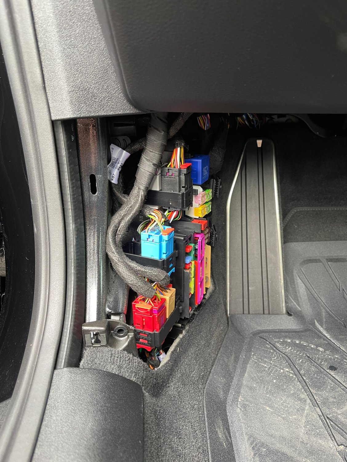
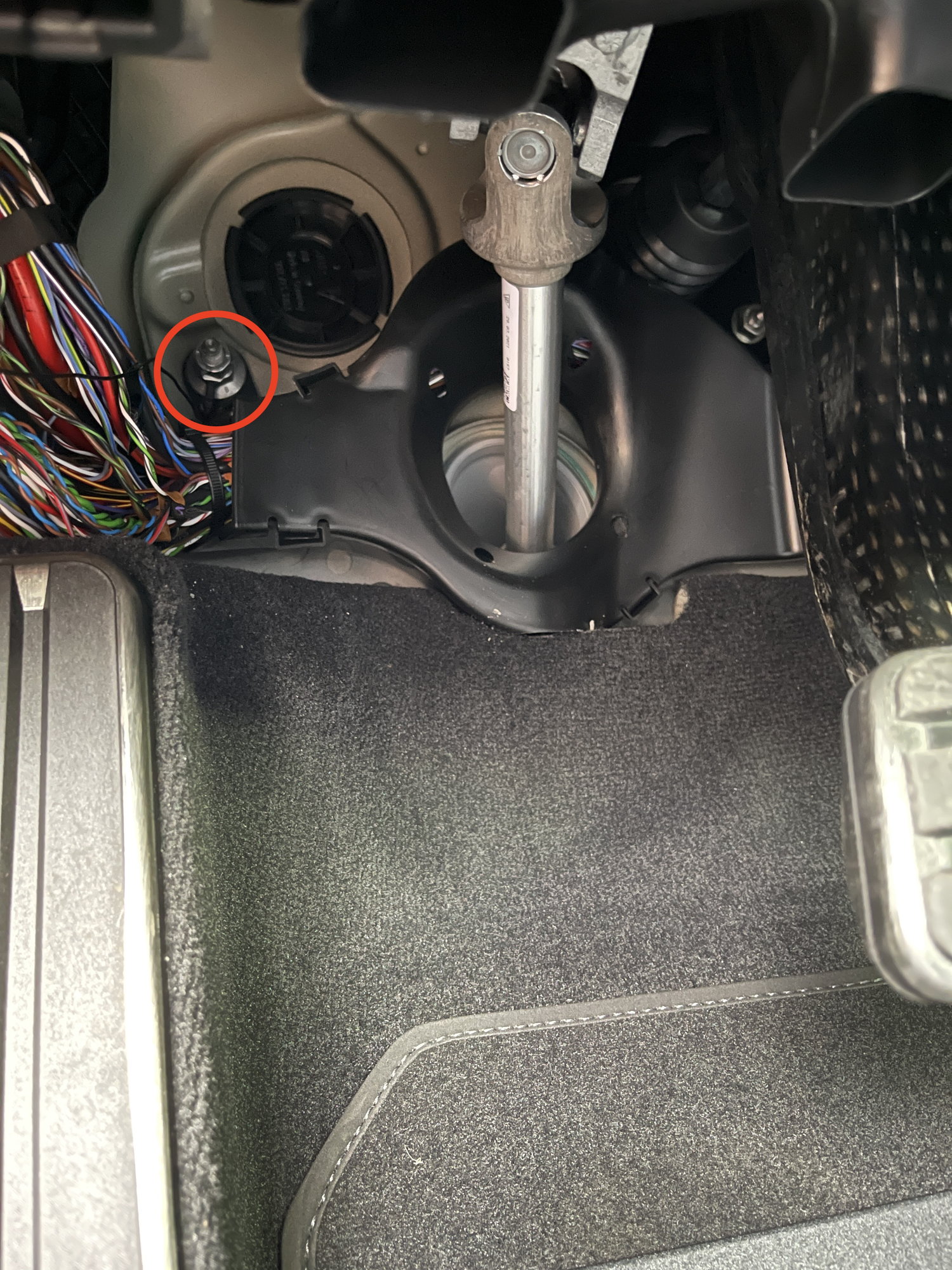
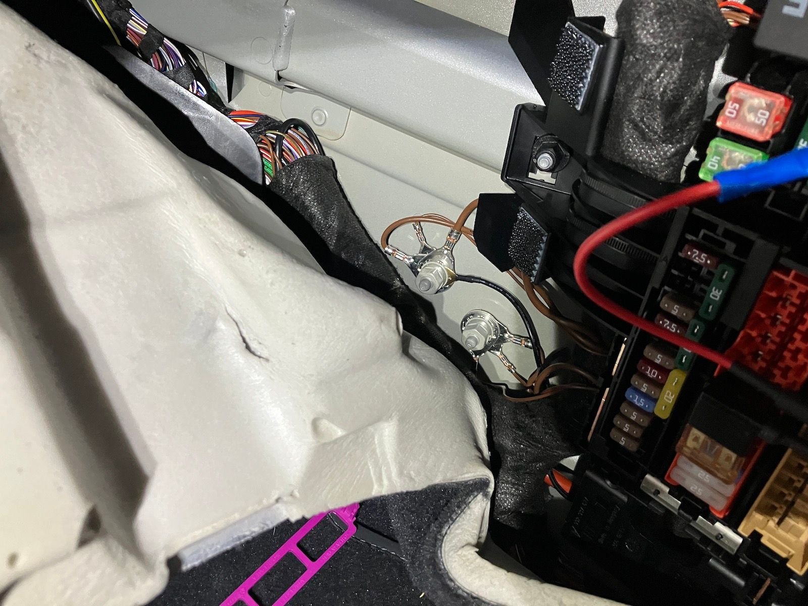
I'm planning on using the existing ground that achilleas101 posted (on the right side of this image), unless that's a terrible idea for some reason.
No reason not to use it, I did on my C2S, no problems/ I guess its good to try to avoid breaking contact on the existing grounds whilst you have the nut off, just to avoid the potential for generating an error code on some ECU
Hey guys, I hardwired the car yesterday and wanted to share my experience.
One major caveat that this is my first time doing anything of the sort, so for anybody reading this in the future, I would NOT rely on my post below as something to go by .
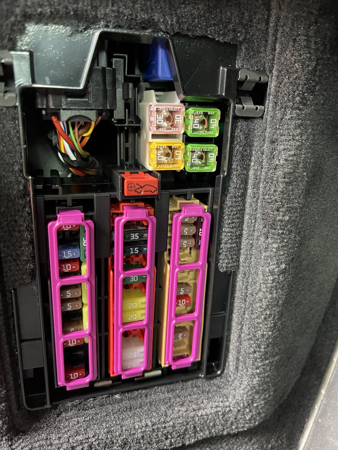
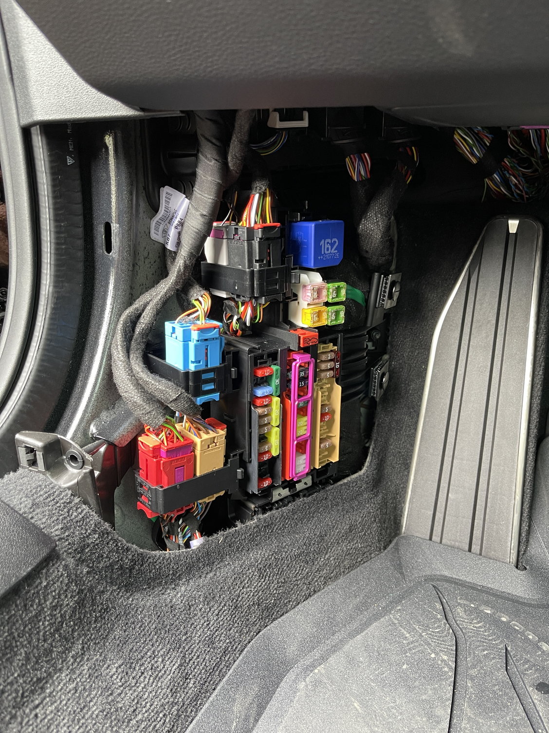
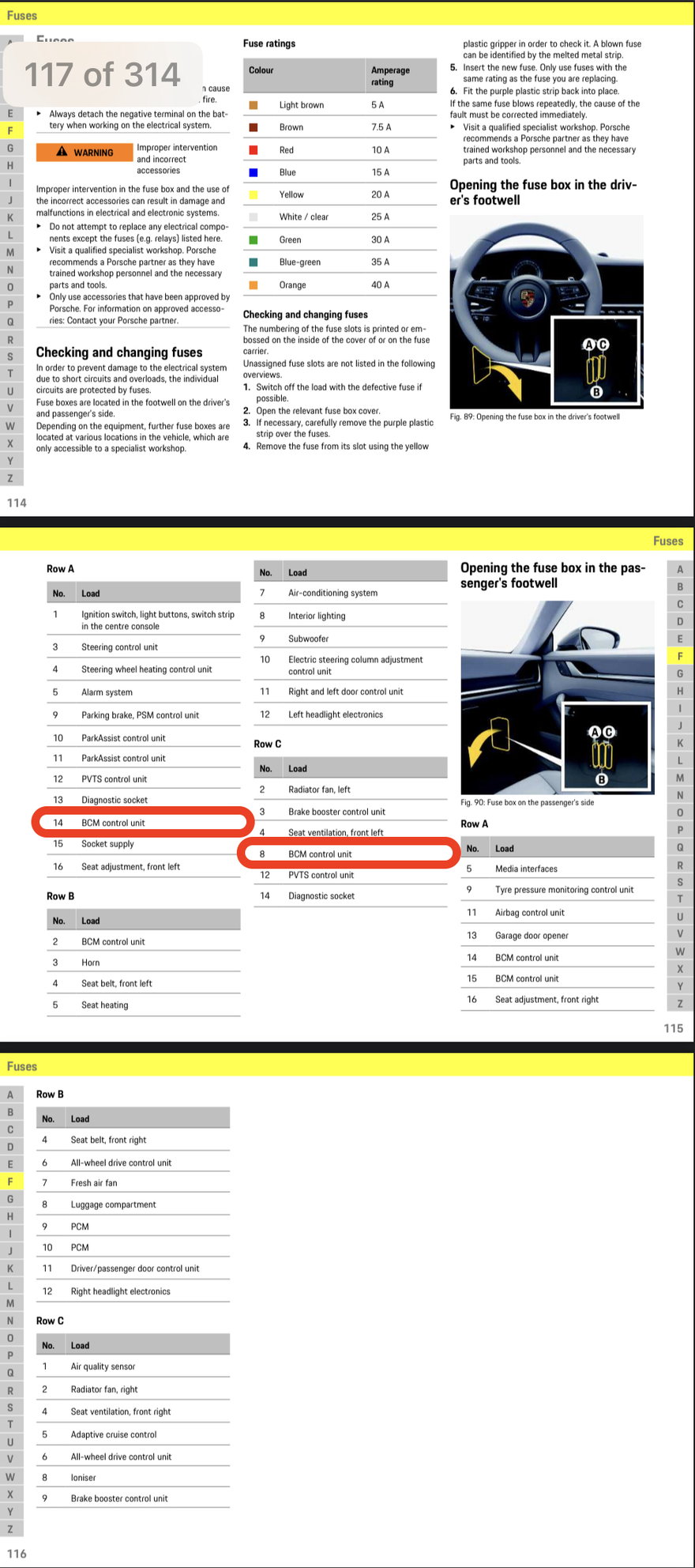
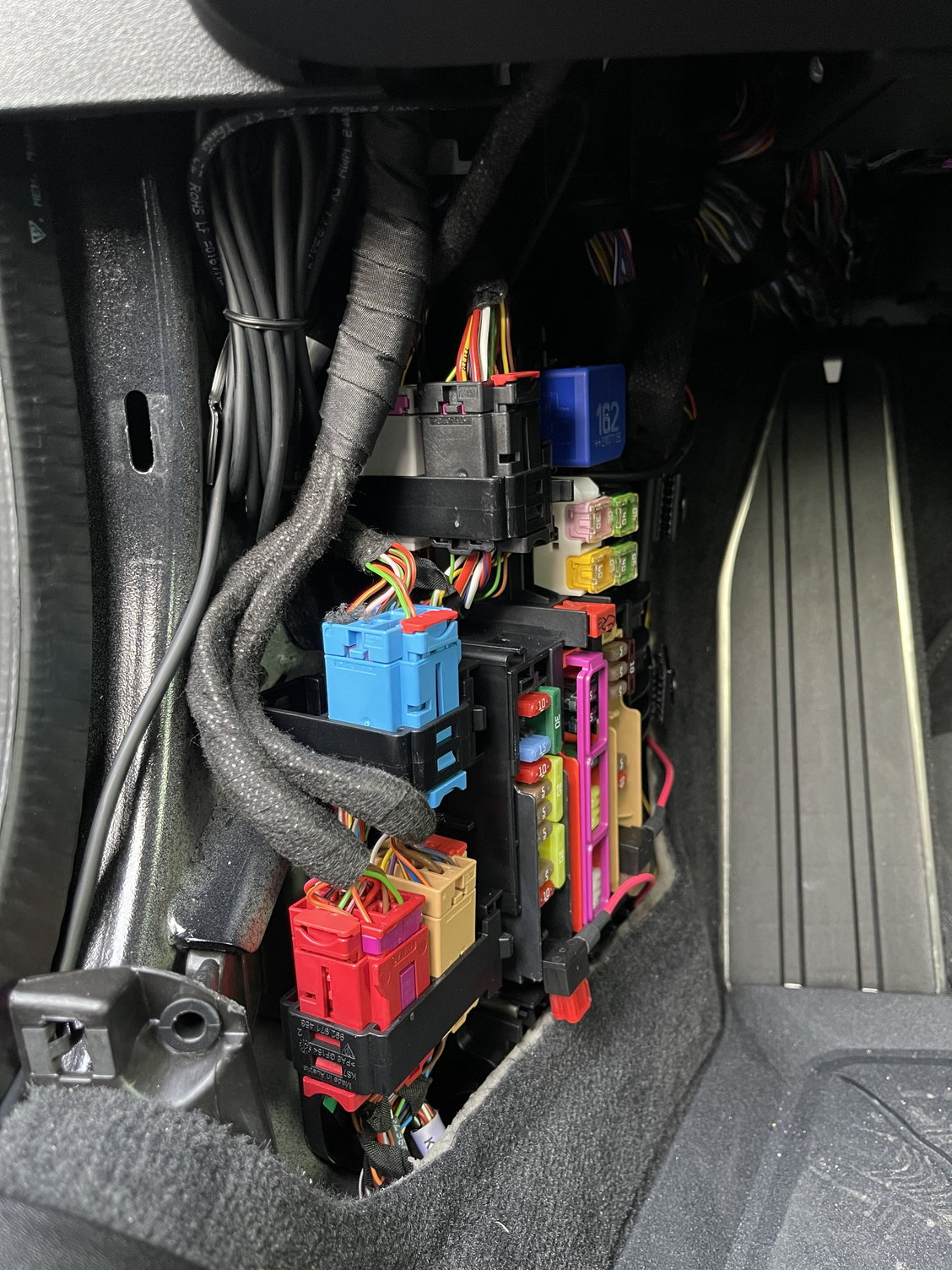
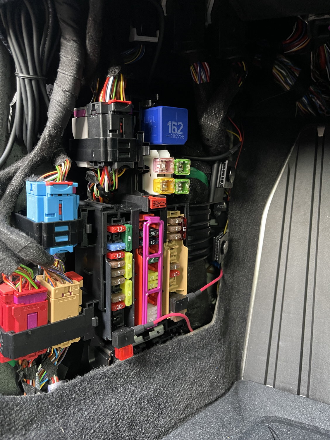
With that said, I thought the process was relatively straightforward. I decided to use the passenger side fuse box since it had more empty slots. As many folks already noted, the fuse box diagram in the manual is completely wrong. As a result, I used a multlimeter to find constant and switched power and found two empty fuses in this fuse box that seemed to provide constant (A bank) and switched power (C bank). Both of these banks take mini fuses. For the ground, I used the existing ground bolt shown in my previous post.
I tested it last night and it all seems to work, including Parking Mode.
A few oddities that I'm still trying to figure out (refer to pictures for more info):
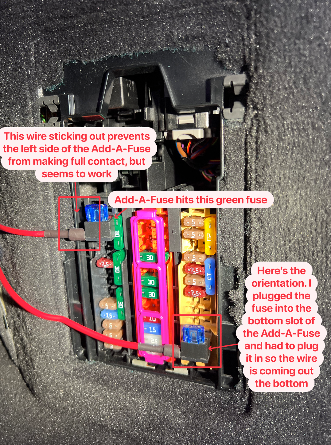
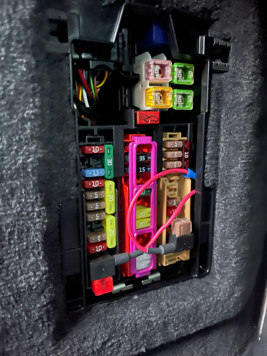
After sticking in the Add-A-Fuse, I can't put the pink fuse box cover back on due to the height of the Add-A-Fuse. I'm guessing that's pretty normal?
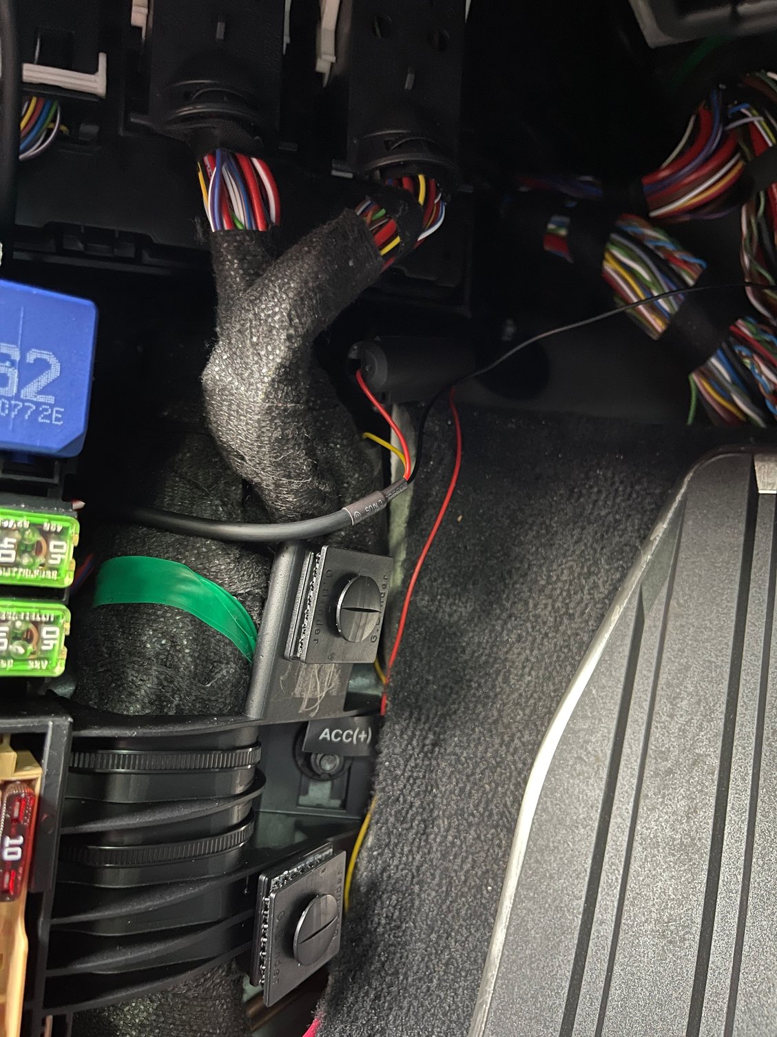
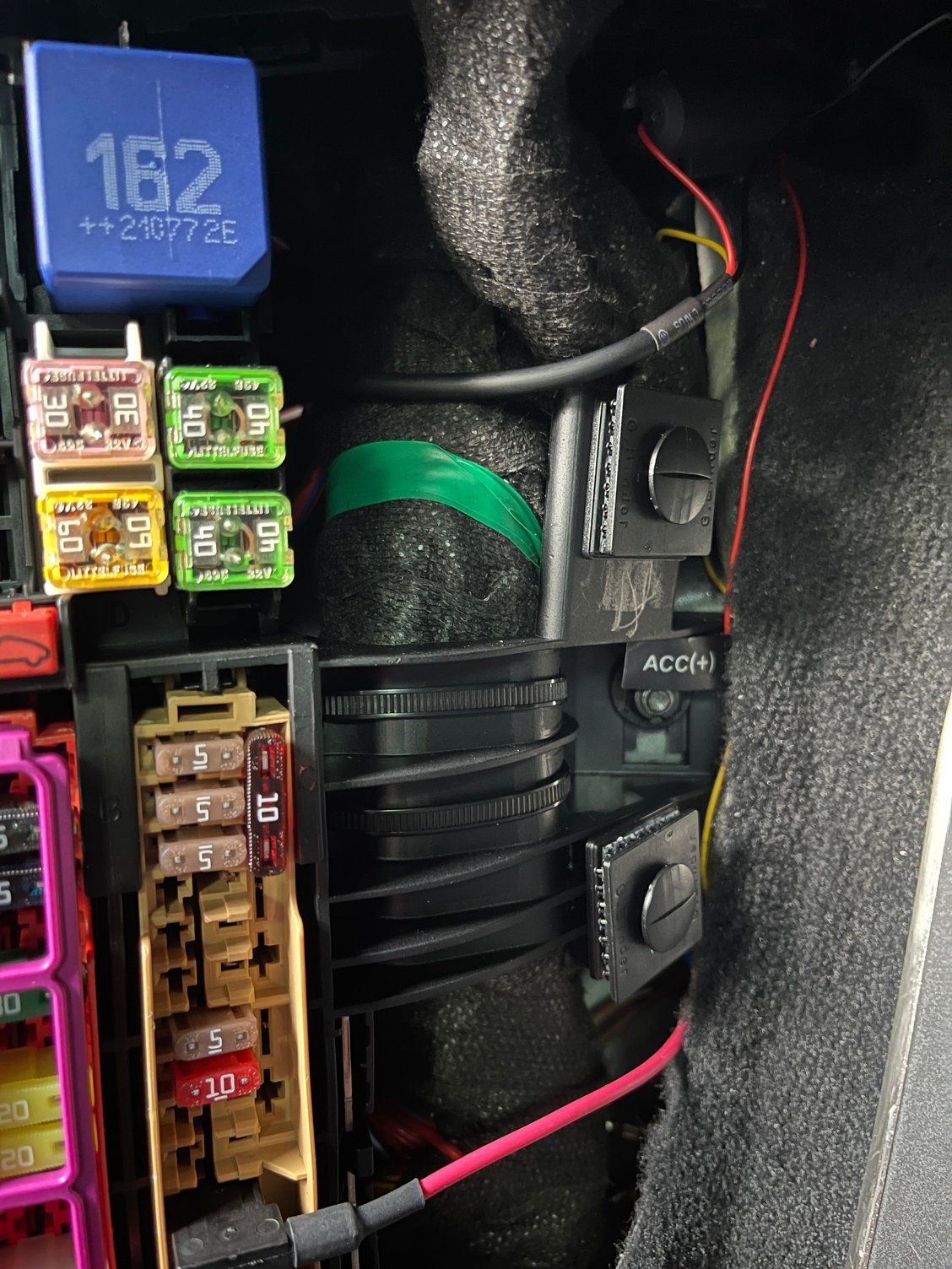
Additionally, the constant power Add-A-Fuse doesn't make perfect contact in the Fuse Box, since the wire leading out of it hits the side of the fuse box.
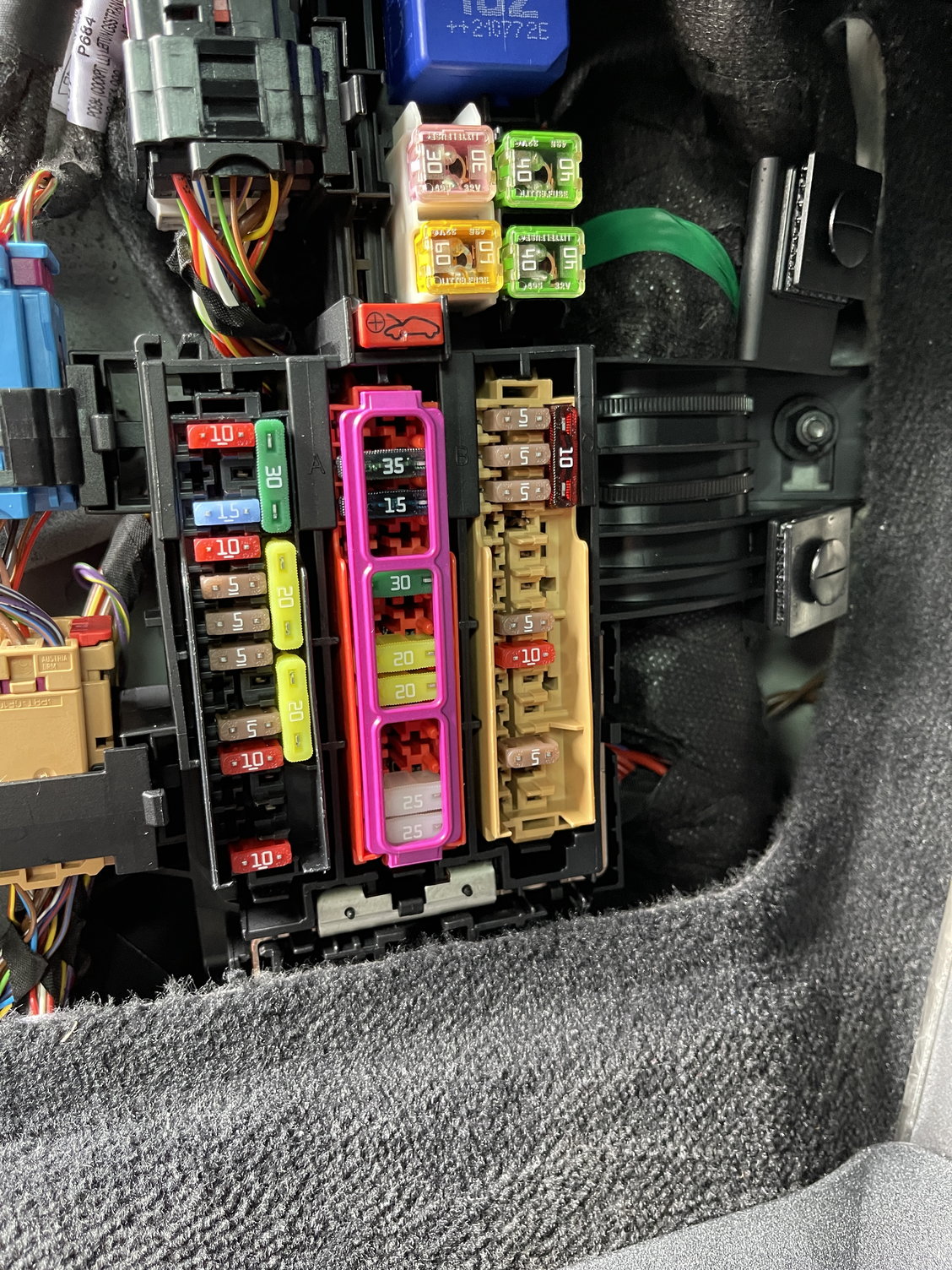
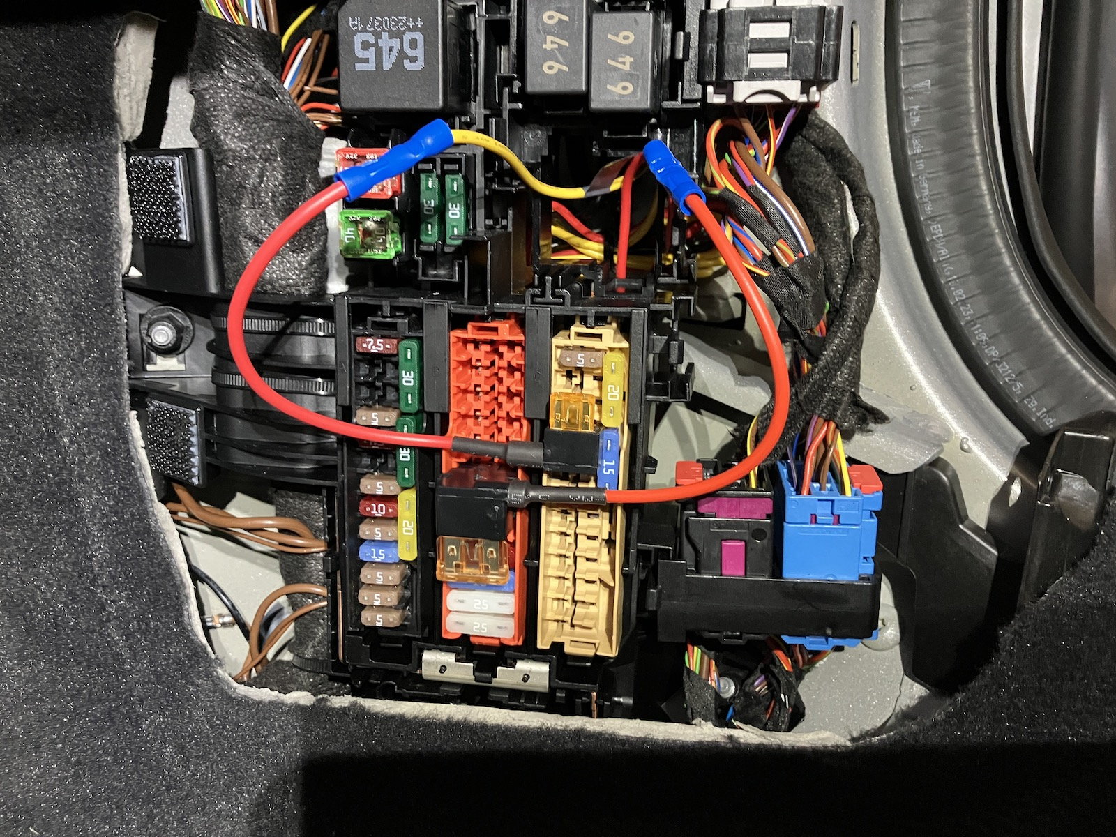
I got a little confused about the orientation the Add-A-Fuse should go in. I followed some instructions online and plugged everything in as I thought it should go... but it didn't work. I flipped the orientation (to what I thought was incorrect) and now it's working. Seems odd since the fuse box literally shows the positive and negative sides but for some reason, when I test using a multimeter, it seems like the terminals that are marked as negative have power and the terminals marked as positive don't. The final orientation I'm using can be shown in the picture above. You will note that these are the OPPOSITE orientation of OP's photos, although he routed his down to the drivers side fuse box. While I don't feel super confident about the three bullets above, everything seems to power on...
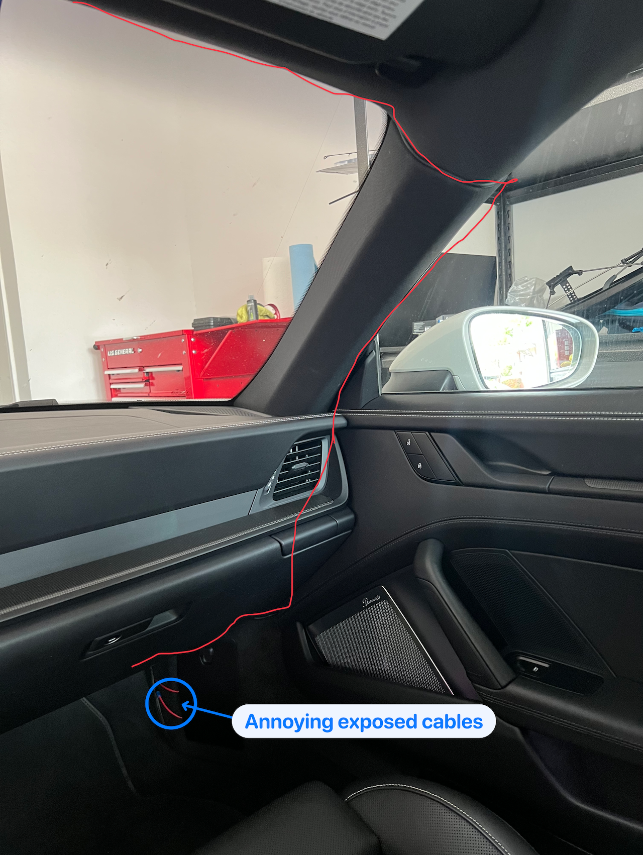
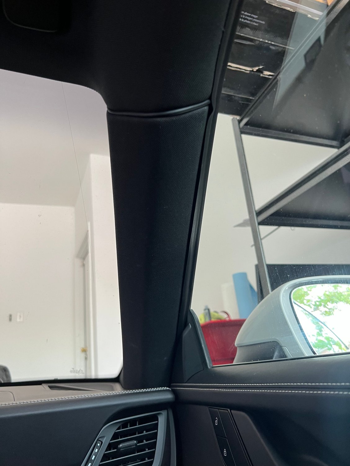
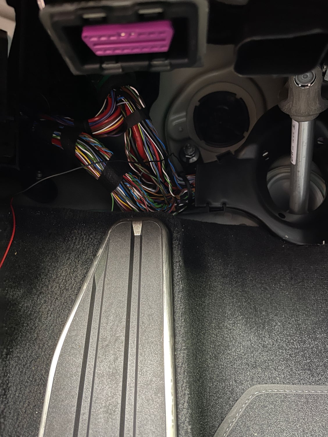
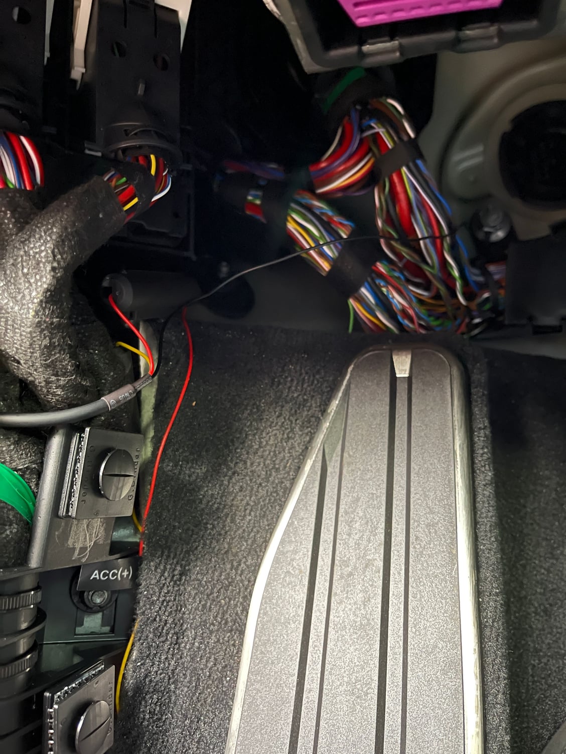
Here's how I routed the cable. Still need to tidy it up a little bit. Can someone confirm this routing won't interfere with the airbags? Also, is there any way to clean up the red cables exiting the fuse box below?
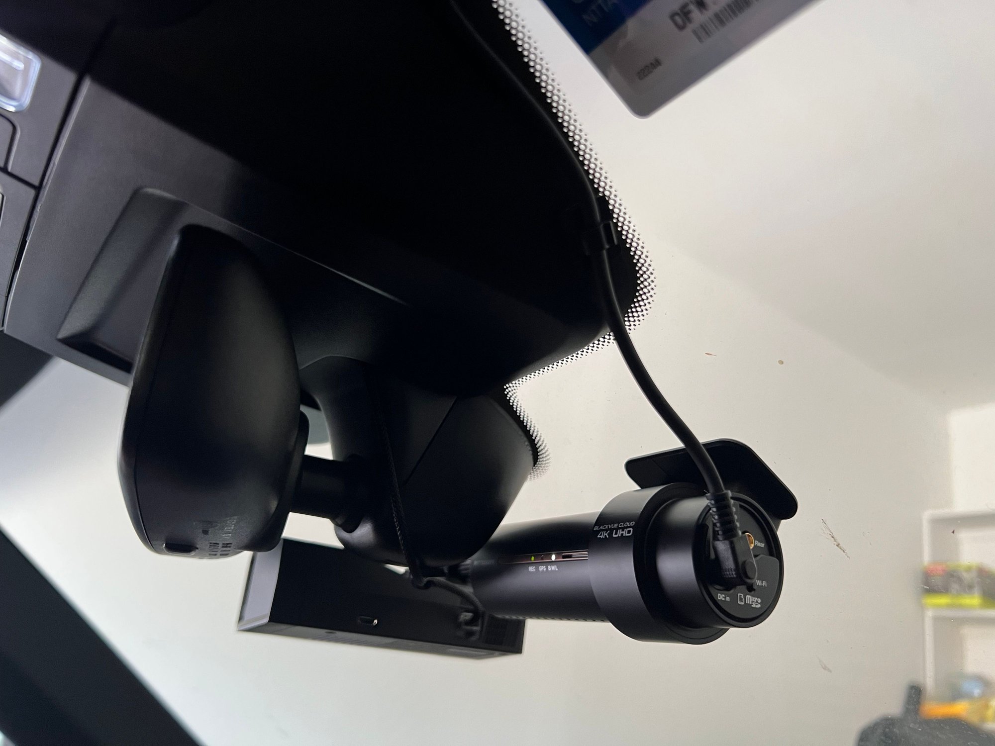
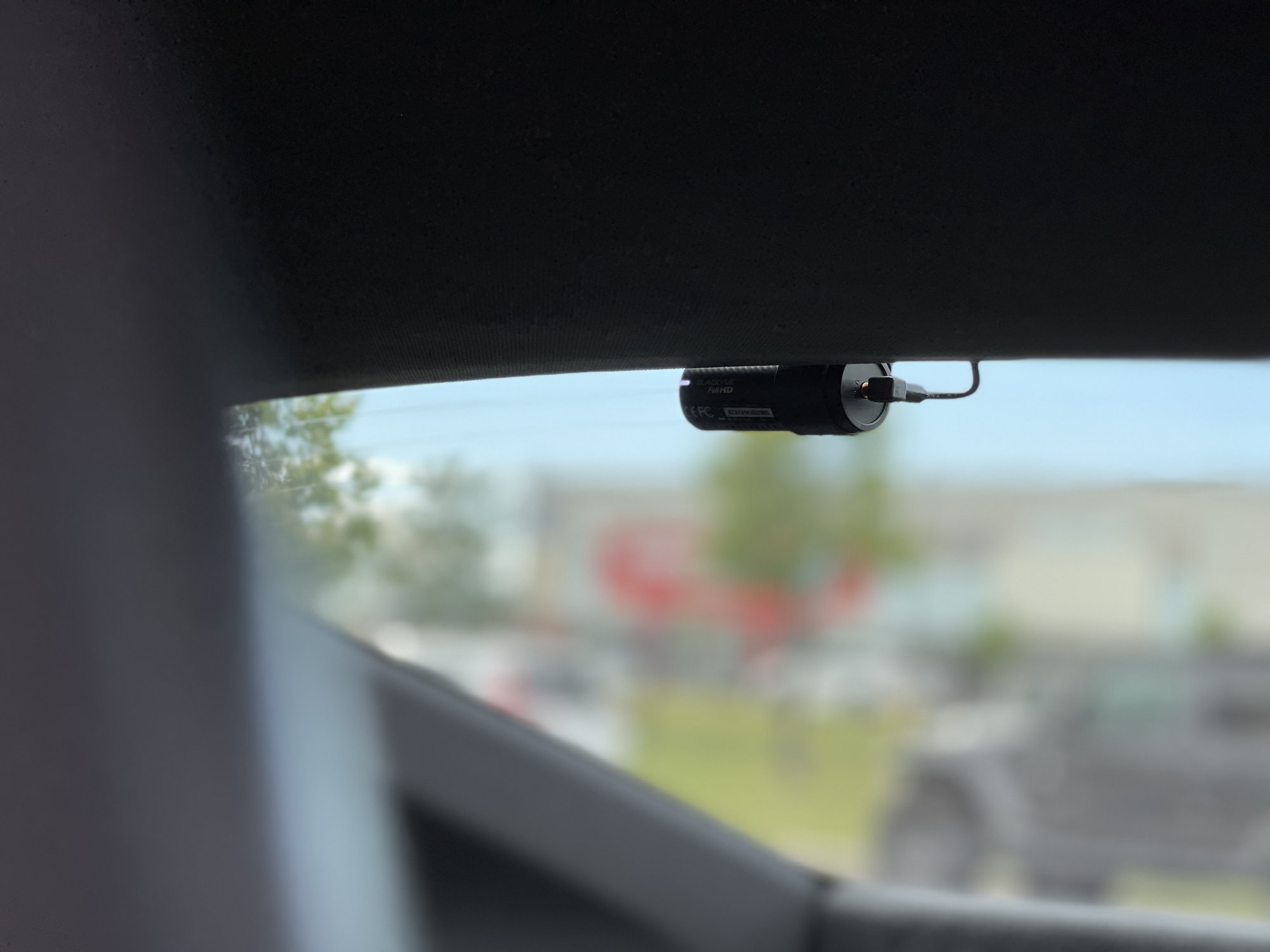
BlackVue annoyances: The rear camera cable included in the box of the BlackVue is too short to reach the rear camera (lol). Looks like I'll have to order a longer cable from them. Also, I can't get any other MicroSD cards to work in the BlackVue, even after formatting them. Seems like a ploy to make you buy their dedicated SD cards...
Feed The Wire From The Windshield Roof Liner To The Passenger Side A Pillar Up To The Passenger Side Door Weather Stripping Then B Pillar To The Side Glass Roof Liner To Finally The Rear Glass Roof Liner
@GTS2022 - were you able to figure out the final fuse layout? I'm about to install on my 992 Turbo S. Also, did you run the wire down the driver's side and use that bolt for ground between the dead pedal and brake?
@GTS2022 - were you able to figure out the final fuse layout? I'm about to install on my 992 Turbo S. Also, did you run the wire down the driver's side and use that bolt for ground between the dead pedal and brake?
Thanks in advance!
No I didn�t yet since I wasn�t able to find out exactly what fuse I�m going to tap into. Manual seems little off in fuse lay out. I�ll work on it the coming weekend.
No I didn�t yet since I wasn�t able to find out exactly what fuse I�m going to tap into. Manual seems little off in fuse lay out. I�ll work on it the coming weekend.
I believe you don't count fuses, because the manual goes 1,3,4 etc. The list for Col A isn't 1-14 as it doesn't use all the numbers. Maybe because of the 2 vertical fuses?
Actually finally got around to installing mine tonight. Everything went well. Took longer than expected. Except since I routed Power to the Driver�s fuse box I couldn�t get it working until I realized I used a screw post that wasn�t grounded.
I can�t seem to located a grounded screw to attach the ground to on the driver�s side. Manual so there�s a clutch up there too. I did confirm that was my issue. When I touch the ground to some exposed body, the Dashcam turns on (with the ignition on) of course.
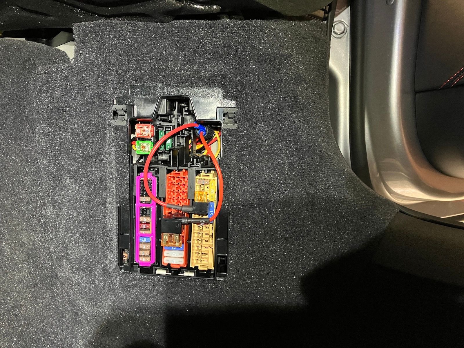
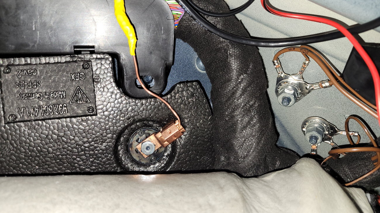
I just installed the parking mode kit for my Viofo A139 Pro dashcam, hardwiring it to the passenger side fuse box. The car is a 992 GT3 RS. I'll post pics here in case it helps anyone else. I grounded to the ground screw behind the carpet.. I had to bend the wire terminal from the parking mode kit a bit to fit around the car's grounding stud. For fuse taps, I needed a source of constant/battery power, and a source of ignition power. Using a multimeter, it seems the left two columns of fuses are battery power (always on), and the right column has power when the key is on (ignition). The middle column required a larger, classic size fuse tap, while the right column took a smaller type, I think it's a "Normal Mini" type. I used a 5A fuse in each. I crimped the fuse taps onto the wires from the parking mode kit, and ran them back through the square hole in the fuse area, and up the side trim and A pillar trim.
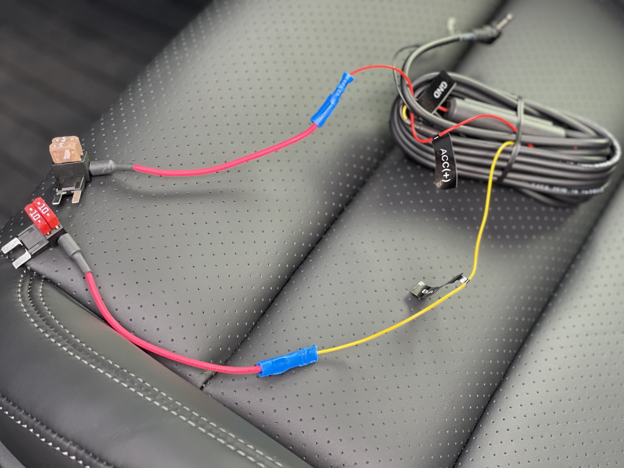
Ground wire from the dashcam is black.
Two fuse taps, left is constant power, right is ignition power.
Final result before putting fuse box cover back on.
Question for @KH0 or anyone else who installed a rear camera: where did you tuck the excess wire for the rear camera? I ended up with maybe 4-5 feet of extra wire. I was thinking of coiling it up and tucking it in the rear side small window (just behind the seatbelt area) under the headliner, but it seems too tight and I can't get all that wire up there.
Question for @KH0 or anyone else who installed a rear camera: where did you tuck the excess wire for the rear camera? I ended up with maybe 4-5 feet of extra wire. I was thinking of coiling it up and tucking it in the rear side small window (just behind the seatbelt area) under the headliner, but it seems too tight and I can't get all that wire up there.
In the read head liner, just pull it down gently so as not to bend it
I went with a more traditional install (former 12v installer) - The fuse taps look shoddy IMO.
At the top of the drivers fuse box there is 2 large plugs and a smaller one to the left. The middle one has a thin black wire which is 12v accessory, the far right one has a thick red/blue wire (35A) which is your 12v, ground is behind the dead pedal.

 04-01-2023, 12:41 PM


 .
.