When you click on links to various merchants on this site and make a purchase, this can result in this site earning a commission. Affiliate programs and affiliations include, but are not limited to, the eBay Partner Network.
Hmm that's interesting. Would you mind sketching the diagram for your 981? My impression is the 981 is the same wiring as the 997 (switched V- / GND). It's not obvious how it could be different than both the 991 (switched V+) and 997 (switched V-) unless the solenoid itself is different.
I'll try to sketch it. Not sure if 981 solenoid is exactly the same. It looks a bit different. It (solenoid) has "+" and "-" signs on the body but ECM V+ is connected to solenoid's "-" and ECM V- is connected to the solenoid's side marked with "+". Yes, I checked a few times. Harness is reversed this way. It's weird but that's how it is. Although I'm not sure if polarity has a big meaning for something like a solenoid unless it has a permanent magnet inside. Or maybe it's just my car? Anyway 4-wire solution makes me not care much.
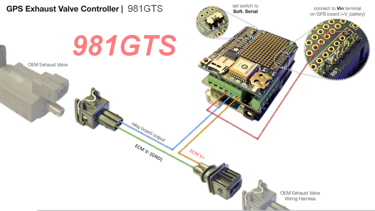
OK, I tried to combine and modify your drawings and here is what I've got. That's pretty much how it's is in my 981GTS (if I had to use a passthru configuration instead of 4-wires). Polarity in ECM side connector is just flipped compared to both 991GT3 and 997GT3.
OK, I tried to combine and modify your drawings and here is what I've got. That's pretty much how it's is in my 981GTS (if I had to use a passthru configuration instead of 4-wires). Polarity in ECM side connector is just flipped compared to both 991GT3 and 997GT3.
Nice modification work! That's really odd, though... that says that the solenoid must be a different type where the polarity is reversed. Can you easily access the solenoid and take a picture of the connector area (with the connector disconnected) to show the (+) or (-) marking on the side?
The side of the connector that is closest to the rear bumper is connected to ECM V+ (output) and it shows "-" at the same time (stamped on the solenoid).
ECM V+ goes from ~+0.6V to +14.5V (Loud/quiet modes, triggered by exhaust button). Car's battery voltage is ~0.2V higher (approx. +14.7V). 0.2V is most likely a voltage drop out on ECM's switching FET.
Voltages were measured between ECM V+ and ECM V- of the connector and also between ECM V+ and chassis ground and results were the same. ECM V- seems to be hardwired to chassis ground according to Ohmmeter. Also there is zero voltage between ECM V- and chassis GND in all exhaust modes. I assume I'd see some voltage variation if ECM V- was a switched line.
Originally Posted by Mech33
Nice modification work! That's really odd, though... that says that the solenoid must be a different type where the polarity is reversed. Can you easily access the solenoid and take a picture of the connector area (with the connector disconnected) to show the (+) or (-) marking on the side?
That is really odd... why would the solenoid stamping be incorrect? To confirm, are you taking all of these measurements while the valve is actually connected to the wiring (doing so with an in-line harness that lets you probe while the system is functioning)?
Here is what another Cayman GTS owner measured with such a harness:
PSE state, Black wire (-) voltage, Brown wire (+) voltage
PSE on, 0V, 13V
PSE off, 14V, 13V
If his measurements are correct, then his GTS valve signaling is similar to the 997, except that energizing the valve makes the exhaust loud rather than quiet.
But that is still different than you measure... the only difference being that he sees battery voltage on the (+) side rather than ground, which matches the solenoid labeling.
Unfortunately I haven't confirmed any of this first hand on a 981, but I'd be happy to do some time with my debug harness. I'm not far from your location.
Originally Posted by sbel
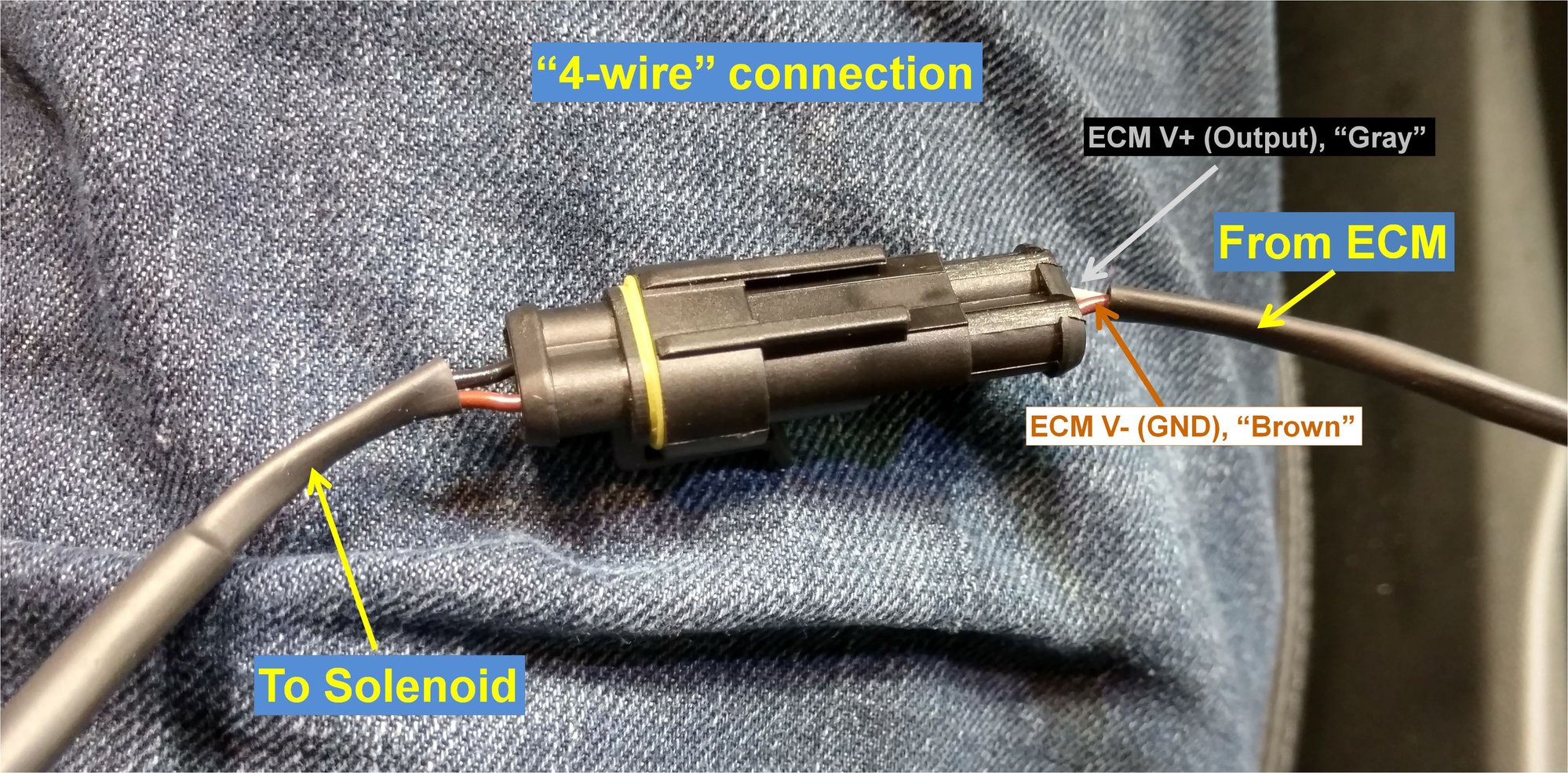
Yep, it's odd and I checked few times hoping that I was really missing something... Few pictures I took during the 4-wire installation:
The side of the connector that is closest to the rear bumper is connected to ECM V+ (output) and it shows "-" at the same time (stamped on the solenoid).
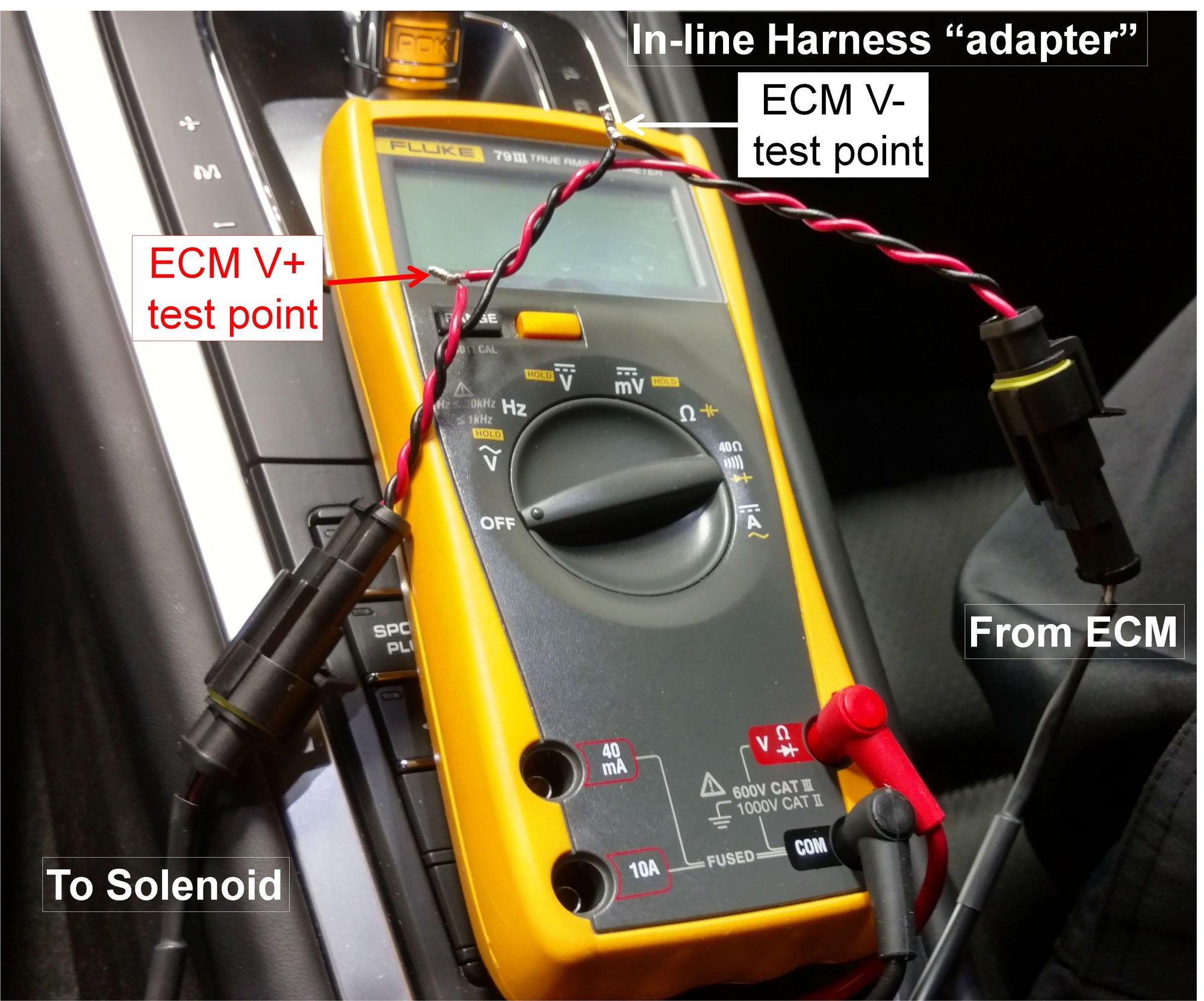
ECM V+ goes from ~+0.6V to +14.5V (Loud/quiet modes, triggered by exhaust button). Car's battery voltage is ~0.2V higher (approx. +14.7V). 0.2V is most likely a voltage drop out on ECM's switching FET.
Voltages were measured between ECM V+ and ECM V- of the connector and also between ECM V+ and chassis ground and results were the same. ECM V- seems to be hardwired to chassis ground according to Ohmmeter. Also there is zero voltage between ECM V- and chassis GND in all exhaust modes. I assume I'd see some voltage variation if ECM V- was a switched line.
I can only guess that maybe factory harness connection was flipped on ECM module side in my car (if there is a connector that allows something like that. But it won't change the fact that ECM V- is hardwired to the GND in my car.
Yes, initially I measured both ways - with and without the load (solenoid) and saw no difference. My first harness had a 3-wire passthrough configuration, so I could do it. I was really puzzled with what I saw and tried to test it extensively. I can check it one more time. Just need to make a small adapter with open contacts (in-line harness) that will allow that or plug in 25 Ohm (that's the DC resistance of the solenoid) directly to the ECM V+/V- connector and measure it this way.
There is another odd thing that I see. I usually do these checks while my car is warming up (idling). If I disconnect a solenoid (easy with 4-wire connection) I can hear exhaust getting louder immediately (that's with PSE switched to QUIET mode) on IDLE. But then I plug it back in and try to use PSE button and hear no difference on IDLE. I can hear the difference when I rev it up though! I assumed that it's also due to engine mapping being changed when PSE button is used. But that's the only thing I can think about.
I'd be happy to meet with you if you have time and desire to do so! A sanity check of what I'm doing definitely won't hurt.
Originally Posted by Mech33
That is really odd... why would the solenoid stamping be incorrect? To confirm, are you taking all of these measurements while the valve is actually connected to the wiring (doing so with an in-line harness that lets you probe while the system is functioning)?
Here is what another Cayman GTS owner measured with such a harness:
PSE state, Black wire (-) voltage, Brown wire (+) voltage
PSE on, 0V, 13V
PSE off, 14V, 13V
If his measurements are correct, then his GTS valve signaling is similar to the 997, except that energizing the valve makes the exhaust loud rather than quiet.
But that is still different than you measure... the only difference being that he sees battery voltage on the (+) side rather than ground, which matches the solenoid labeling.
Unfortunately I haven't confirmed any of this first hand on a 981, but I'd be happy to do some time with my debug harness. I'm not far from your location.
I can only guess that maybe factory harness connection was flipped on ECM module side in my car (if there is a connector that allows something like that. But it won't change the fact that ECM V- is hardwired to the GND in my car.
Yes, initially I measured both ways - with and without the load (solenoid) and saw no difference. My first harness had a 3-wire passthrough configuration, so I could do it. I was really puzzled with what I saw and tried to test it extensively. I can check it one more time. Just need to make a small adapter with open contacts (in-line harness) that will allow that or plug in 25 Ohm (that's the DC resistance of the solenoid) directly to the ECM V+/V- connector and measure it this way.
There is another odd thing that I see. I usually do these checks while my car is warming up (idling). If I disconnect a solenoid (easy with 4-wire connection) I can hear exhaust getting louder immediately (that's with PSE switched to QUIET mode) on IDLE. But then I plug it back in and try to use PSE button and hear no difference on IDLE. I can hear the difference when I rev it up though! I assumed that it's also due to engine mapping being changed when PSE button is used. But that's the only thing I can think about.
I'd be happy to meet with you if you have time and desire to do so! A sanity check of what I'm doing definitely won't hurt.
That all sounds very odd to me... I need to check out a Cayman GTS.
The side of the connector that is closest to the rear bumper is connected to ECM V+ (output) and it shows "-" at the same time (stamped on the solenoid).
ECM V+ goes from ~+0.6V to +14.5V (Loud/quiet modes, triggered by exhaust button). Car's battery voltage is ~0.2V higher (approx. +14.7V). 0.2V is most likely a voltage drop out on ECM's switching FET.
Voltages were measured between ECM V+ and ECM V- of the connector and also between ECM V+ and chassis ground and results were the same. ECM V- seems to be hardwired to chassis ground according to Ohmmeter. Also there is zero voltage between ECM V- and chassis GND in all exhaust modes. I assume I'd see some voltage variation if ECM V- was a switched line.
Just l looked at those pics. Is that valve only a 2-port? It looks like there is a cap over the 3rd port. Have you traced out where those vacuum lines go exactly?
On the 991, the 3-port valve switches the common connection (the exhaust valves) between a vacuum source, or an atmosphere source, depending on solenoid state (energized vs. not).
If the 3rd port is plugged on the Cayman, then the system must operate differently and all bets are off until I understand more about the vacuum plumbing of the system...
Actually I need to retract what I said about sound not changing at IDLE when using PSE button. It does. Looks like this button just doesn't work when car is cold started. It's locked in "quiet" mode for a few moments. After that it works normally and I hear sound changing same way as when I just unplug the solenoid.
Originally Posted by Mech33
That all sounds very odd to me... I need to check out a Cayman GTS.
Just l looked at those pics. Is that valve only a 2-port? It looks like there is a cap over the 3rd port. Have you traced out where those vacuum lines go exactly?
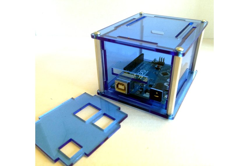
Update: I worked with a custom acrylic case designer to have a case fabricated that better fits this taller board stack at a reasonable cost. You can order it in a variety of translucent colors here for $10 shipped: https://www.tindie.com/products/mjri...losure-duo-ii/
Update: I worked with a custom acrylic case designer to have a case fabricated that better fits this taller board stack at a reasonable cost. You can order it in a variety of translucent colors here for $10 shipped: https://www.tindie.com/products/mjri...losure-duo-ii/
Update: I worked with a custom acrylic case designer to have a case fabricated that better fits this taller board stack at a reasonable cost. You can order it in a variety of translucent colors here for $10 shipped: https://www.tindie.com/products/mjri...losure-duo-ii/
 03-09-2016, 01:52 AM

 Harness is reversed this way. It's weird but that's how it is. Although I'm not sure if polarity has a big meaning for something like a solenoid unless it has a permanent magnet inside. Or maybe it's just my car? Anyway 4-wire solution makes me not care much.