When you click on links to various merchants on this site and make a purchase, this can result in this site earning a commission. Affiliate programs and affiliations include, but are not limited to, the eBay Partner Network.
Many of you probably already seen the 991 GT3 PSE GPS valve controller DIY. I had posted a 981 Cayman PSE GPS valve controller DIY based on the 991 GT3, however there is an error in my DIY direction and I decided to write up a new set of instruction for 981 Cayman GTS and I will do the same as soon as I get my hands on 981 cayman GT4 in a few short weeks. To clarify Do not use 991 GT3 directions for Cayman or any other vehicle as I have not personally confirmed whether they work or not. Proceed at your own risk! If you blow up your ECU, which is extremely unlikley, please do not blame me. Ok... now on to the good stuff!
Because the Cayman GTS PSE valves works differently than 991 GT3 the Harness is different
+ wire will be the Pass through as voltage does not change. Thus, the red wire in the wiring harness is the V+ and it does not change so the red wire will be connected to both plug on the positive lead
Red wire will be connect on the same side on both end of the port When facing the female side of the plug with metal spring wire on top, please note the Right side plug is V+
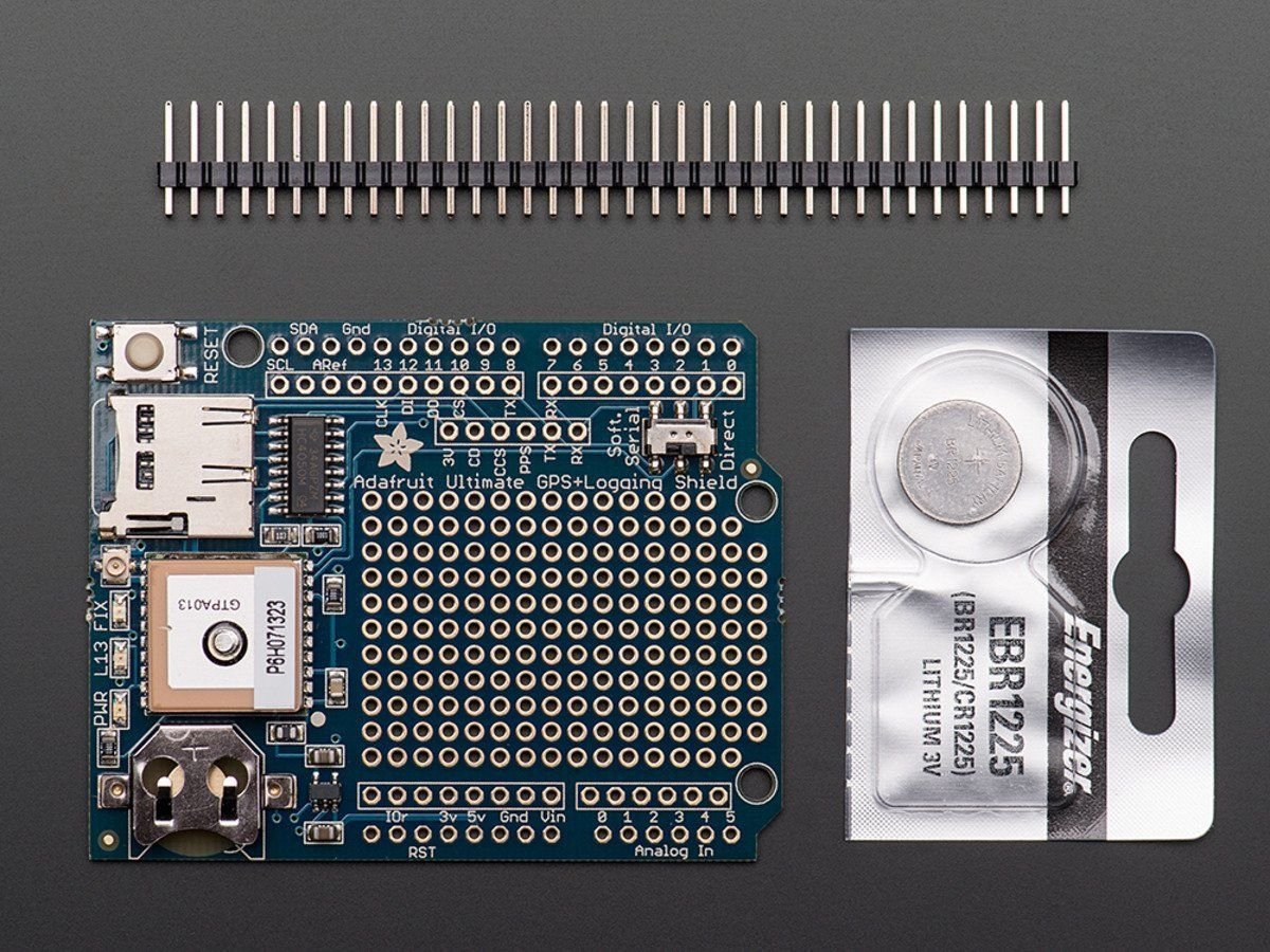
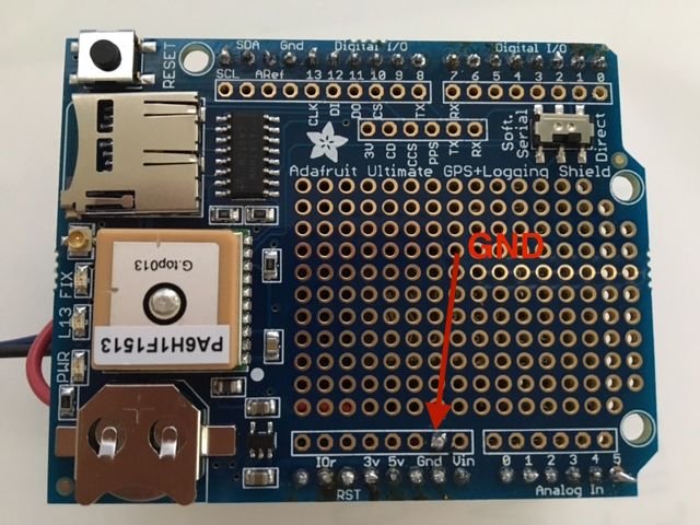
The processor board, relay board, and GPS board all simply plug into each other. But before you can plug them all in, you have to solder the pin headers onto the GPS board, and solder one extra jumper wire onto the board for the GND to drive the solenoid on demand.
Carefully snap the pin headers into the appropriate number in each group to match the holes around the perimeter of the GPS module, assemble them from underneath, and solder them from above. When done it should look like the picture below (note that this picture is the final assembled stack):
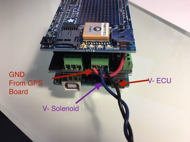
Now extend your blue and black wiring from the solenoid harness either directly or through some intermediate connectors and jumper harnesses and route them into these specific terminal connections on the relay board shown below (terminal block 2). It�s important to get these exactly right:
- the �NO2� (Normally Open 2) should connect to the GND wire connection you soldered to the GPS board. This is the GND source.
- the �COM2� (Common 2) should connect to the -V_solenoid-side blue wire connection from your solenoid wiring harness
- the �NC2� (Normally Closed 2) should connect to the -V_ECU-side BLACK wire connection from your solenoid wiring harness
It�s important to use this specific terminal block since the software that will run on the processor board is only designed to flip this specific relay. Goofing up this wiring might damage your ECM if you accidentally short the battery voltage to the ECM-side connection, so triple check everything and of course proceed at your own risk!! Here is what the connections should look like when done:
This is the main difference between 991 GT3 and 981 Cayman GTS. Big thanks to @Mech33 who walked me though this entire procedure. I also borrowed many photos from his DIY. I hope this helps the community. I will update or put up a new thread when I get to the 981 GT4!.
Please read the rest of the 991 DIY for how to program and such!
Do you know a good way of just turning off the exhaust solenoid for tracks like Laguna Seca? I'd rather shut it off in general, then after the track day, switch it back to OEM
Do you know a good way of just turning off the exhaust solenoid for tracks like Laguna Seca? I'd rather shut it off in general, then after the track day, switch it back to OEM
Not sure about the Cayman variants, but with a GT3, if you wire the exhaust flaps closed, the exhaust gets hot and a few folks have melted part of the bumper.
Not sure about the Cayman variants, but with a GT3, if you wire the exhaust flaps closed, the exhaust gets hot and a few folks have melted part of the bumper.
Yikes! It looks like I'm going to sit this one out. Thanks for the help
Not sure about the Cayman variants, but with a GT3, if you wire the exhaust flaps closed, the exhaust gets hot and a few folks have melted part of the bumper.
FWIW I wired my 981's valves shut for a Nurburgring trackday with reasonable ambient temps (up to 25C) and had no issues at all with the exhaust getting too hot.
Afterwards in a dyno environment the car was having ignition timing issues/pinging with the valves forced closed but this was with an aggressive ECU tune and a very hot dyno environment. Out on the track it seemed to work fine.
 02-28-2016, 06:05 PM