When you click on links to various merchants on this site and make a purchase, this can result in this site earning a commission. Affiliate programs and affiliations include, but are not limited to, the eBay Partner Network.
If you're handy with a soldering iron this is the best way to go.....
With standard bright LEDs from the local electronic supply shop (you'll need 7) these numbers worked out (no specs were provided but these should be close for most LEDs).
They never had a 1 watt resistor so I ran 4 470 ohm 1/4 watt resistors in parallel instead. It worked out great.
Way better than changing or sorting out corroded bulbs.
If you're handy with a soldering iron this is the best way to go..... With standard bright LEDs from the local electronic supply shop (you'll need 7) these numbers worked out (no specs were provided but these should be close for most LEDs). They never had a 1 watt resistor so I ran 4 470 ohm 1/4 watt resistors in parallel instead. It worked out great. Way better than changing or sorting out corroded bulbs.
I had some time in the office this a.m. so I did the conversion on my latest 968 and thought I'd post a simple procedure.
Materials:
-5mm white LEDs (qty 7). I used 7000MCD but anything above 5k should be good (MCD is simply the intensity of the light).
-470 ohm 1/4 watt resistors (qty 4). I could not find a 120 ohm 1 watt resistor and I'm not sure if they even make these so use the 1/4 watt.
-Soldering iron w/ solder and experience on how to use it.
-Thin gauge wire
-X-acto or a sharp hobby knife
-Sidecutters
-Multimeter (would be good to have but not necessary)
Procedure:
1. Remove the light from your hatch simply by undoing the two screws.
2. If the clips aren't broken, separate the circuit board from the lens assembly carefully by gently prying up the retaining clips and pulling the two units apart.
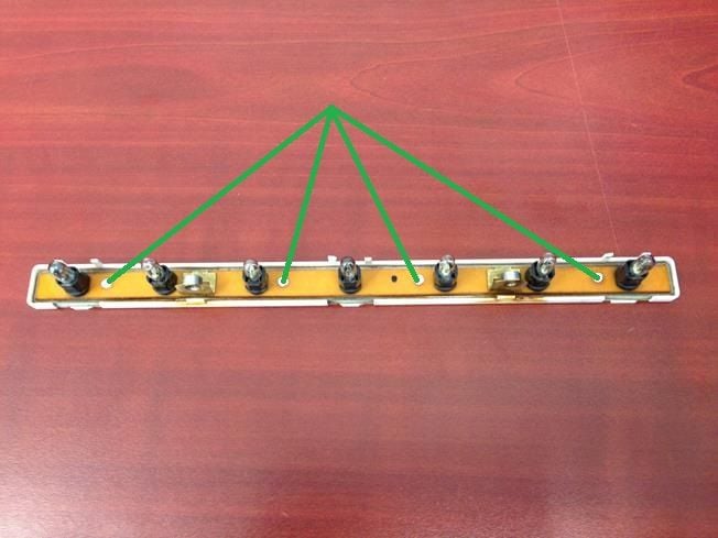
3. Heat the 4 plastic studs with your soldering iron to separate the circuit board from the housing and pull apart the 2 units:
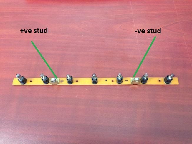
4. Mark the positive stud (left side) and negative stud (right side):
5. Use your soldering iron to remove all seven bulb units from the circuit board. Be careful not to apply too much heat so you don't separate the board traces from the actual board. Also be careful not to crack the board.
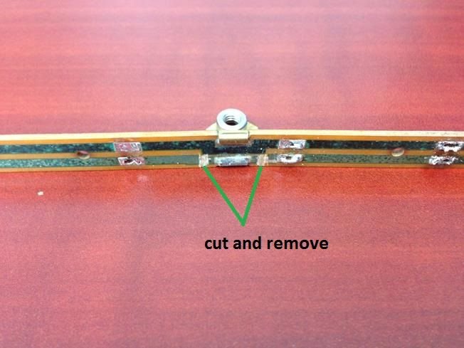
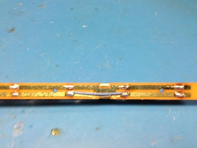
6. Using a knife, cut and remove the traces on both sides of the positive stud to separate the stud from the circuit. Use a multimeter to confirm there is no bridging:
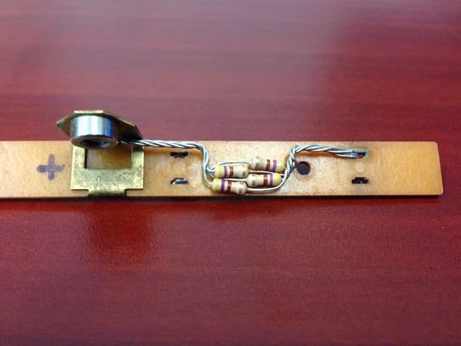
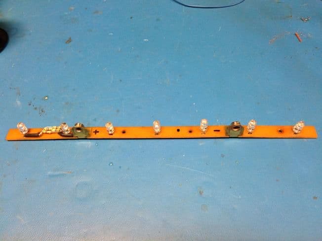
7. Assemble the 470ohm (x4) resistors in parallel as shown in the photo below. One side will be soldered to the positive stud and the other side will be soldered in with the positive side of the last LED as shown. Use some shrink wrap or electrical tape to insulate the conductors:
8. Solder in the 7 LEDs. Be sure to put the cathode side of the LED on the negative terminal strip (trace). The cathode can be identified by having a flat spot on the LED or by the shorter lead coming out of the bulb. I mounted mine about 4mm off the board:
9. Using the thin gauge wire, run a jumper to bridge the two traces that were originally separated from the positive stud:
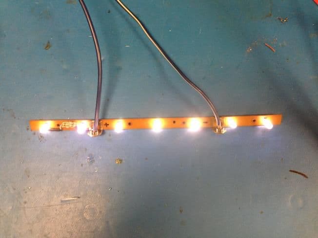
10. If you have a power supply, set it at 13.5V and test it. If not, no worries:
11. Mount the board on the plastic housing and reheat the 4 studs to reconnect the 2 pieces.
12. Hopefully, you'll never have to do this again so seal it up with some clear silicone and you're good to go. This is especially good if the white plastic tabs are broken.
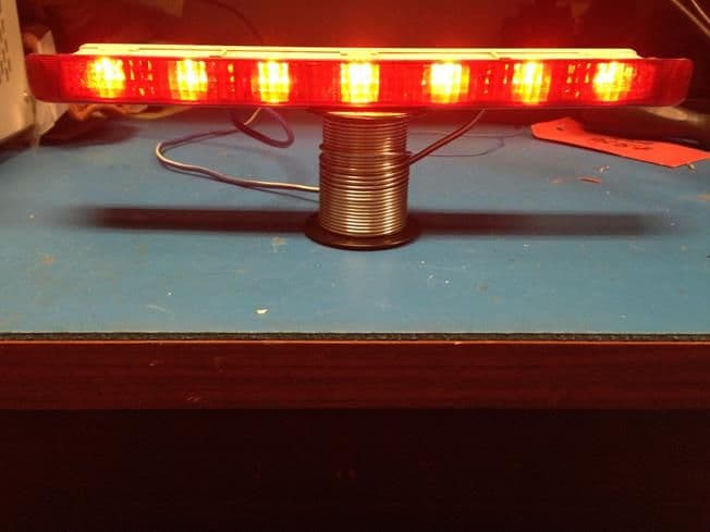
Voila!:
Note: I mounted the base of the LEDs 4mm off the board. If I had to do this again I would probably go with something closer to 15mm so that the LEDs penetrate more into the lens and the light is more dispersed. But for now I'm happy with what I have.
I had some time in the office this a.m. so I did the conversion on my latest 968 and thought I'd post a simple procedure.
Materials:
-5mm white LEDs (qty 7). I used 7000MCD but anything above 5k should be good (MCD is simply the intensity of the light).
-470 ohm 1/4 watt resistors (qty 4). I could not find a 120 ohm 1 watt resistor and I'm not sure if they even make these so use the 1/4 watt.
-Soldering iron w/ solder and experience on how to use it.
-Thin gauge wire
-X-acto or a sharp hobby knife
-Sidecutters
-Multimeter (would be good to have but not necessary)
Procedure:
1. Remove the light from your hatch simply by undoing the two screws.
2. If the clips aren't broken, separate the circuit board from the lens assembly carefully by gently prying up the retaining clips and pulling the two units apart.
3. Heat the 4 plastic studs with your soldering iron to separate the circuit board from the housing and pull apart the 2 units:
4. Mark the positive stud (left side) and negative stud (right side):
5. Use your soldering iron to remove all seven bulb units from the circuit board. Be careful not to apply too much heat so you don't separate the board traces from the actual board. Also be careful not to crack the board.
6. Using a knife, cut and remove the traces on both sides of the positive stud to separate the stud from the circuit. Use a multimeter to confirm there is no bridging:
7. Assemble the 470ohm (x4) resistors in parallel as shown in the photo below. One side will be soldered to the positive stud and the other side will be soldered in with the positive side of the last LED as shown. Use some shrink wrap or electrical tape to insulate the conductors:
8. Solder in the 7 LEDs. Be sure to put the cathode side of the LED on the negative terminal strip (trace). The cathode can be identified by having a flat spot on the LED or by the shorter lead coming out of the bulb. I mounted mine about 4mm off the board:
9. Using the thin gauge wire, run a jumper to bridge the two traces that were originally separated from the positive stud:
10. If you have a power supply, set it at 13.5V and test it. If not, no worries:
11. Mount the board on the plastic housing and reheat the 4 studs to reconnect the 2 pieces.
12. Hopefully, you'll never have to do this again so seal it up with some clear silicone and you're good to go. This is especially good if the white plastic tabs are broken.
Voila!:
Note: I mounted the base of the LEDs 4mm off the board. If I had to do this again I would probably go with something closer to 15mm so that the LEDs penetrate more into the lens and the light is more dispersed. But for now I'm happy with what I have.
Have fun!
Excellent, thanks for sharing. A must have for cab owners.
 10-28-2014, 01:40 PM