When you click on links to various merchants on this site and make a purchase, this can result in this site earning a commission. Affiliate programs and affiliations include, but are not limited to, the eBay Partner Network.
1 No connect
2 No connect
3 Spoiler moter terminal 2
4 Spoiler moter terminal 1
5 Earth/Ground
6 +12 through 15 amp fuse, always on
7 +12 from J25, switched (7.5 amp fuse)
8 F57 on central informer
9 Terminal 3 "extend" on manual switch, "spoiler up" limit switch
10 Terminal 5 "retract" on manual switch, "spoiler down" limit switch
11 Common on manual switch
12 G56 - speed signal
13 No connect
14 No connect
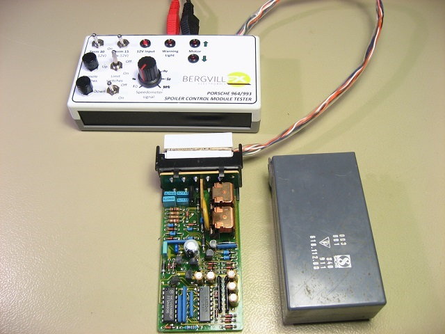
To check the motor, wires, and limit switches from the controller plug:
Limit switches and wiring:
Spoiler down, 9 - 11 open, 10 - 11 closed
Spoiler up, 9 - 11 closed, 10 - 11 open
Spoiler mid position - 9 - 11 and 10 - 11 open
Motor and wiring:
CAUTION: you will damage the motor or the mechanism if you drive past "full up" or "full down"
Put +12 and neg on 3 - 4. Polarity determines motor direction.
To check controller operation on work bench:
Put fused 12 volt power on 6 and 7, neg/ground on pin 5
If either relay operates, replace the driver transistor
Jumper pin 3 to pin 11, the "extend" relay should operate. Jumper pin 9 to pin 11, and the relay should drop out.
Jumper pin 10 to pin 11, the "retract" relay should operate. Jumper pin 10 to pin 11, and the relay should drop out.
If you have a function generator, you can put a pulse signal on pin 12 and simulate the auto-extend and auto-retract.
Love this thread. Question for the forum. The spoiler alert light is on until the car reaches 7km/hr and extinguishes if all is well. If it doesn’t go out, what is that signalling, or what condition drives that alert?
I have sourced supplies of the BC337 transistors (dirt cheap), two integrated circuits (cheap) and the relays (not so cheap). The ICs and relay are out of production so it seemed worthwhile stockpiling.
Next step is to build a test rig so I can replicate the in-car situation, complete with a speed signal. Then I can fix the three known ones with issues in New Zealand and maybe help out a few international owners.
That�s what I�m hoping, but pays to be ready just in case. A relay went on my Turbo Control Unit when I owned a Turbo so the correct relays were my biggest purchase. They weren�t cheap. I don�t want to offer to fix local ones and have a long delay finding parts. All in all it�s just an interest and reliving my youth as an avionics technician.
I made a simple test rig for this control unit years ago, and have repaired about 150-200 of them. There are many things that can go wrong in these, depending on the unit version. The most common faults are failing relays and transistor drivers, but this is almost always combined with other component failures. There are at least three versions of these units, the earlier are analogue with opamps, and the latest has a microcontroller.
The warning light extinguish at 7km/h to indicate that the unit receives a valid VSS speed pulse signal. When exceeding 80km/h, the unit will try to raise the spoiler, and activate the warning light if the spoiler does not reach the upper limit switch within a certain number of seconds, and same at spoiler retract.
Cheers,
Tore
I made a simple test rig for this control unit years ago, and have repaired about 150-200 of them. There are many things that can go wrong in these, depending on the unit version.
Not really, unless the units were misdiagnosed as the problem and were then tested incorrectly. The relatively small number of postings on Rennlist is indicative of a very low failure rate,
e.g. most postings are with regard to changing the up/down speeds. The later module is even more reliable, as it uses a microcontroller.
I made a simple test rig for this control unit years ago, and have repaired about 150-200 of them. There are many things that can go wrong in these, depending on the unit version. The most common faults are failing relays and transistor drivers, but this is almost always combined with other component failures. There are at least three versions of these units, the earlier are analogue with opamps, and the latest has a microcontroller.
The warning light extinguish at 7km/h to indicate that the unit receives a valid VSS speed pulse signal. When exceeding 80km/h, the unit will try to raise the spoiler, and activate the warning light if the spoiler does not reach the upper limit switch within a certain number of seconds, and same at spoiler retract.
Cheers,
Tore
Thanks Tore. I see you didn�t use the Porsche plug. Is there a more reasonably priced easily sourced option?
I made the connector out of Plasticard, veroboard and some pins I had lying around. Much faster (done in 30 minutes) and easier than trying to source the original connector.
Cheers,
Tore
I made the connector out of Plasticard, veroboard and some pins I had lying around. Much faster (done in 30 minutes) and easier than trying to source the original connector.
Cheers,
Tore
Surprisingly, the pins are the outrageously priced item. I've had no luck tracking down the full OE connector.
Doing more research on the speed signal I get the following. Does it sound right?
Each wheel revolution produces 8 counts on the speed sensor.
The OE tire was a 225/50/16 which had a circumference of 1.984m
If the car is travelling at 80km/hr, then the wheel is travelling 22.22 metres per second or completing 11.2 revolutions. With eight counts per revolution the frequency is 89.6 Hz.
Therefore, when the spoiler controller detects an approx 90 Hz signal it extends the spoiler.


 12-26-2014, 12:57 PM