Notices
964 Forum 1989-1994
Sponsored by:
Sponsored by:

Oil Circulation Diagram?

Thread Tools
 
Search this Thread
 
Old 04-11-2013, 02:14 AM
  #16  
Vandit
Nordschleife Master
 
Vandit's Avatar
 
Join Date: Jul 2007
Location: DFW, TX
Posts: 5,614
Likes: 0
Received 48 Likes on 36 Posts
Default

That whole 993 oil filter console retrofit is pretty interesting. Definitely something to consider if/when the engine is out and being rebuilt.

I wonder what kind of reconfigurations were required with regard to the oil lines.

Also, that "tank > engine > floor" diagram had me LOL at lunch. The group of people I was with thought I was going crazy.
Old 04-11-2013, 09:44 AM
  #17  
Babalouie
Burning Brakes
 
Babalouie's Avatar
 
Join Date: Jun 2011
Location: Sydney Australia
Posts: 977
Likes: 0
Received 1 Like on 1 Post
Default

Wait...I think my understanding of the circulation has been the wrong way around


But, but but...the oil gets filtered *after* the motor? Shouldn't it be before?

Because Porsche, I guess..
Old 04-11-2013, 02:49 PM
  #18  
Vandit
Nordschleife Master
 
Vandit's Avatar
 
Join Date: Jul 2007
Location: DFW, TX
Posts: 5,614
Likes: 0
Received 48 Likes on 36 Posts
Default

I guess the idea is that short of user error or outside of "standard operation" oiling system fcukery, the engine would be the only source of foreign matter in the oil.
Old 04-11-2013, 03:16 PM
  #19  
FeralComprehension
Rennlist Member
 
FeralComprehension's Avatar
 
Join Date: Jun 2010
Location: Detroit (Rock City); 1990 C4
Posts: 1,710
Likes: 0
Received 4 Likes on 4 Posts
Default

Originally Posted by alexjc4
Aside from the theoretical oil flow of course there is the actual oil flow which is more like this
Brilliant! (Shouldn't there be a really smoky heat exchanger in there?)
Old 05-17-2020, 02:10 PM
  #20  
jpoint
Burning Brakes
 
jpoint's Avatar
 
Join Date: Mar 2010
Location: Chicago suburbs
Posts: 1,241
Received 356 Likes on 218 Posts
Default

Originally Posted by alexjc4
Your instinct is sound, the 993 added a filter between the tank and pump. It is not unheard of for a dirty tank to ruin a newly built engine as grot is suck in and pumped round the engine.
I'm reviving this thread to ask this question. To avoid the problem noted in the quoted post - could you pour oil in where it is normally added and have that oil drain out of the pipe going into the bottom of the engine (assuming the pipe is disconnected because the engine is out of the car)?
Old 05-17-2020, 02:19 PM
  #21  
jpoint
Burning Brakes
 
jpoint's Avatar
 
Join Date: Mar 2010
Location: Chicago suburbs
Posts: 1,241
Received 356 Likes on 218 Posts
Default

Originally Posted by BigMikeATL
Doh! I have the book 20 feet from me. Thanks.

Here is what I have and really need to know what is the INLET and OUTLET at the oil filter.

Green - after filtration
Red - before filtration
Yellow - oil cooler (bypass)

Attachment 719426
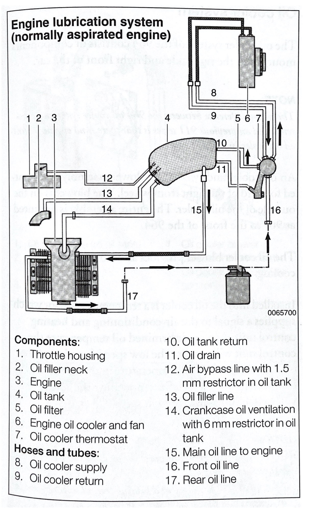
So you would pour oil in at 13 (top of the black line) and drain it out at the end of 24 (the pipe running along the bottom of the wheel well on the passenger side of the car that attaches via hose #26 to the oil tank). I'm asking because I changed the hoses on the oil tank while the engine is being rebuilt. I cleaned around the area before installing the new hoses but I also had to cut the old hoses out. I'm worried I might have knocked some debris into the tank outlet hole in the process. I don't think I did but this would be cheap insurance for the costs of a couple quarts of oil - yes?
Old 05-17-2020, 02:52 PM
  #22  
RicardoD
Rennlist Member
 
RicardoD's Avatar
 
Join Date: Oct 2003
Location: Bay Area, CA
Posts: 1,854
Received 212 Likes on 118 Posts
Default

For additional reference from Adrian's book (go buy his book):


Old 05-17-2020, 03:08 PM
  #23  
jpoint
Burning Brakes
 
jpoint's Avatar
 
Join Date: Mar 2010
Location: Chicago suburbs
Posts: 1,241
Received 356 Likes on 218 Posts
Default

Thanks Ricardo. I'm going to seem a bit dim here (maybe "am" rather than "seem") but I'm having a hard time corresponding the location on line in this diagram to the actual parts I'm looking at in the car. As I look at the car - line #13 in this diagram would be right above line #15 on the oil tank. Line #'s 12 and 14 are closer to the top of the oil tank. Am I reading this wrong. I'll order the book. Thanks again.
Old 05-17-2020, 03:19 PM
  #24  
RicardoD
Rennlist Member
 
RicardoD's Avatar
 
Join Date: Oct 2003
Location: Bay Area, CA
Posts: 1,854
Received 212 Likes on 118 Posts
Default

Jpoint, I have not really worked in this area yet, it is on my list in my C4 project but I am not there yet. So I have to defer to others to help you out as I don't have a mental map yet of the various bits and where they physically are in the car.
Old 05-20-2020, 01:28 AM
  #25  
jpoint
Burning Brakes
 
jpoint's Avatar
 
Join Date: Mar 2010
Location: Chicago suburbs
Posts: 1,241
Received 356 Likes on 218 Posts
Default

Thanks Ricardo - just to be safe I pulled the hose and pipe going to the engine and check the line for debris. Everything is clean.


Quick Reply: Oil Circulation Diagram?


All times are GMT -3. The time now is 01:03 PM.