When you click on links to various merchants on this site and make a purchase, this can result in this site earning a commission. Affiliate programs and affiliations include, but are not limited to, the eBay Partner Network.
I am installing an electrical power steering pump and to control the speed of the pump I need to link the pump to a VSS or speed pulse signal ( car speed not engine speed ) I have looked at the pins on the ECU and found that pins 47 and 48 both relate to speed. One is speed/reference mark positivenand the other is speed/reference mark negative shield. I don't think either of these pins are what I am looking for.
Does any one have a suggestion for were i can pull a MPH speed impulse signal that will work for the power steering pump speed pulse signal?
Of course I can also just wire it up without - but that means the pump will run all the time - max vs reduced speed
Just looking for HELP
If you trace the speedometer line back to the ABS control unit you will see that it is an output of the ABS controller. From personal experience, it will generate a 0-12v pwm signal...so the faster you go the shorter the pulsewidth. I think this is what you want. It is calibrated to the ABS ring (on all but 89c4) and it will output 1 pulse for each tooth. There are 45 teeth on the ABS ring. You'll have to determine if that will work for you power steering pump. An alternative would be some type of DAQ unit like MoTeC that can output a PWM based on wheel speed.
The speed pulse comes from the instrument cluster, and is distributed to the Climate Control Unit and the rear spoiler control module, maybe more units as well. It is also routed to the Motronic engine control module, at least in the 993. I don't have the 964 schematics available here, but would guess it's the same in the 964. It's a White/Red wire both in the 964 and 993. The speed signal is a pulse-width coded signal with about +12V PP.
Cheers,
Tore
ToreB, I don't think your information is correct. In the Porsche wiring diagrams, a Red/White wire is ignition power (term 15). Typically the ABS outputs are a violet wire with a colored stripe.
For a 91-94 C2 you could use either Pin 17 front left(violet/red) or Pin 23 front right(violet/green)
For a 91-94 C4 you only have Pin 16 front left (violet/red)
Geoffrey & ToreB -Thank you both for the input - I have found out that the input to the Power steering pump on the MR2 Toyota was from the ABS system - still trying to find out more - The pump has a built in computer that keys to a power relay as well as internal sensors for demand. While the speed pulse link is not absolutely necessary it does help to reduce load on the electrical pump motor at speed sooner.
Geoffey, in your last post are you indicating that if I found the violet/green wire which is pin 23 (on the ECU???) that that could be used as a source for the speed signal? Or would it be best to go to the ABS controller for the signal ?
I have the wiring diagrams - but those are so small and hard to read - and what a treat to figure out.
Thanks for the feed back -
Do yourself a favor and forget about the MR2 pump. Check the Racing section, someone is selling a 997 Cup pump which is much nicer and integrates better.
The pin numbers I referenced are from the ABS controller, not the ECU. Porsche wiring diagrames are among the best in the business, I really appreciate them when trying to look at BMW ones for instance.
Geoffrey -
I looked up the wire diagram for the ABS - but the numbers don't work -
I found the speed sensor outlet - at 10 and 27 - but the 17 and 23 wire are green and white
See attached wire diagram - ( is this the wrong page ?) says ABS CONTROL UNIT -
Also can you please provide a little more info on the location of information of the 997 pump - can't find in racing classified or racing classified or racing vehicle classified -
You are right on the wire diagram - the C$ is a page above the C2 - must have scrolled up by accident when I grabbed to page -
This is the correct wire diagram and i see the 17/23 pins and colors as you stated - Where do you go to figure out what the L57 and L 121 boxes are that the wires run to -
Thanks for the 997 pump info - guess I will try the MR2 and see what happens.
It will be interesting to see anyway -
Geoffrey, I am correct. The speed pulse is generated by a separate pulse sender, not the ABS, and it is formatted (or cleaned if you want) by the speedometer. The output wire for other units in the car is White/Red. See the cutout from Sheet 6 in the 964 electric manual below.
You may be right about a Red/White wire, I haven't checked this. But beware, I would expect both these wires to exist in our cars, it is certainly the case for the 993. There is a difference between White/Red and Red/White, but it may be difficult to spot for a untrained eye. The first, or "base" colour is slightly wider on the wire, the second colour is a thin band.
I have not been able to find the speedo wire in the 964 engine control schematic sheet, so I would guess it's not connected to this unit. However, the easiest access to this in on the spoiler control module, placed either under the dash in the passenger side, or under the passenger seat.
Cheers,
Tore
L57 is an input to the R52 relay in the central electrics on Sheet 6 which then goes to the speedometer as a green wire and also another control unit which if I trace further will probably be the Spoiler controller and possibly the curise control.
L121 is an input to the Automatic Transmission control unit on Sheet 16
My factory wiring diagram books do not show any pulse sender on any wiring diagrams except for the 1989 model where the pulse sender is a speedometer ring in the gearbox with 6 or 8 teeth on it. 1990 and later models did away with the speedometer ring in the gearbox and went to an output from the ABS system.
Been running MR2 power steering pump since 2013, no speed sensor, NO issues. MR2 pump works great on and off track. Highly recommend if you want to remove mechanical pump.
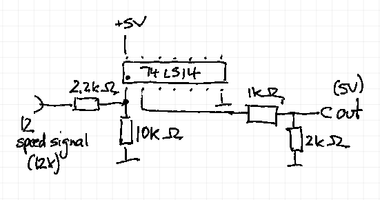
just for reference - if anyone ever needs it. I created my own spoiler controller a while ago and needed the speed signal for 5V logic.
I used one gate of a 74LS14 Schmitt-Trigger circuit and the circuit below transformed the signal from 12V to 5V and created a very clear/clean signal.
Last edited by Hatzenbach; 04-28-2023 at 01:02 AM.


 02-18-2013, 05:38 PM