When you click on links to various merchants on this site and make a purchase, this can result in this site earning a commission. Affiliate programs and affiliations include, but are not limited to, the eBay Partner Network.
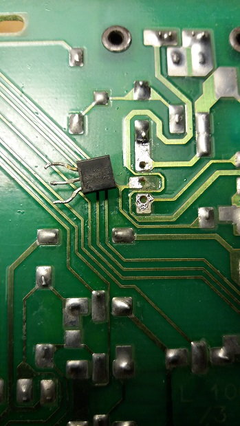
Hi, Just trying to mend a CCU with a fan which wont shut down and have been following advice by ToreB and Jason Andreas. All good so far, however I noticed that part of the pcb was damaged around a hole where the old transistor was soldered. Anyone got any ideas about if its okay to continue and solder the new transistor in place, or should something be done to the pcb first?
I'm not sure anything needs to be done to the board, make sure the surfaces are clean so you get a good solder adhesion.
I have followed the thread instructions and will clean thoroughly with denatured alcohol before carrying on. I was hoping the solder would be able to adhere okay, even with a bit broken. just got to work out how to get the transistor in there!
Last edited by 5hrine; 02-02-2018 at 05:07 AM.
Reason: spelling
Is there circuitry on both sides of board? If so, there's a core that goes through board to connect the two sides. If you pulled the core out, you'll have to jump the connection with a small wire. Otherwise you can bend the transistor lead down onto existing cladding to make a good contact.
The partially damaged pad is the base connection of the BC337 and what's left of the pad is sufficient for the small current flow. The board is single sided so no problem with making a good connection on the other side of the board.
This'll be fine, bend the transistor leg over the remaining solder pad to get a good connection.
Cheers,
Tore
Just soldered the new transistor onto the pcb, two of the legs are okay , but the leg on the damaged pad is not so good, it looks as if the remaining bit of the pad has lifted away from the board. is there a fix or is the board scrap?
Last edited by 5hrine; 02-05-2018 at 06:52 AM.
Reason: add photo
You have probably pushed the pad up from the board when inserting the transistor, and possibly used a too hot soldering iron.
There is no need for scrapping the PCB. The broken pcb track can be fixed and reconnected, but this require good soldering skills and experience.
Cheers,
Tore
You have probably pushed the pad up from the board when inserting the transistor, and possibly used a too hot soldering iron.
There is no need for scrapping the PCB. The broken pcb track can be fixed and reconnected, but this require good soldering skills and experience.
Cheers,
Tore
And then the transistor may not have even been bad to begin with. Was the transistor initially tested?
In my opinion there's no need for testing the transistor other than to observe the CCU behaviour. If the unit does not turn off within 20 minutes after ignition off, the transistor is shot.
A quicker test is to first ensure that the CCU is off by briefly disconneting the battery, then turn the ignition briefly on. (1-2 sec) The CCU shall turn on, but go off within 5-10 seconds.
Cheers,
Tore
Going back to a question in my original post HERE, is there an easy way to test a transistor without removing it from the PCB?
Yes, as is the case for testing any transistor, whether in a PCB or external, the use a VOM set to ohms can determine a bad transistor.
The base collector junction of any bipolar transistor is basically a simple PN junction like any diode, as is the case for the base emitter
junction. Since the suspect switching transistor just switches the coil of the CCU's power relay, it's basically an open circuit when reverse
biased using an ohmmeter. So measuring from the collector to the emitter or to the base should indicate very high resistance (megohms)
if good. Yes, other PCB components connected to the collector of the suspect transistor can affect the measurement, but because of
the unique design used in the CCU, it is not affected and basically somewhat isolated from the other components of the relay coil
and suspect transistor.
In my opinion there's no need for testing the transistor other than to observe the CCU behaviour. If the unit does not turn off within 20 minutes after ignition off, the transistor is shot.
A quicker test is to first ensure that the CCU is off by briefly disconneting the battery, then turn the ignition briefly on. (1-2 sec) The CCU shall turn on, but go off within 5-10 seconds.
Cheers,
Tore
Over the last 10 years rebuilding 964/993 CCU's, a simple transistor replacement doesn't always solve the shut-down problem, even when the suspect transistor
was indeed bad and replaced. The circuit design of that section of the CCU is marginal. Also as an example, the CCU's microcontroller may think the engine is
still too warm keeping the CCU alive, i.e. that function of the CCU is not that simple.
Remember, once the CCU is removed, it can be easily tested for shut-down by just attaching three wires; K2(#30), K1(grd), G35(#15) - only momentarily to turn-on.
The CCU should turn-on and then turn-off in about 10 seconds. This will verify whether the suspect transistor is O.K.


 02-01-2018, 01:32 PM