When you click on links to various merchants on this site and make a purchase, this can result in this site earning a commission. Affiliate programs and affiliations include, but are not limited to, the eBay Partner Network.
I'm now hoping to get the temperature and fuel gauges working. The temperature would show the temperature of either my motor or controller, not sure which yet. The fuel gauge would show my battery state of charge. Does anyone know where I can tap into these gauges, and what type of signal they are looking for to make them function properly?
I'm also hoping to make the check engine light work...my controller has an output for an error light that I think would work for this. Is there a generic "check engine" light on the dash, and do you know where I could tap into the wire feeding it?
Not sure what to do with the oil pressure gauge...suggestions are welcome!
Maybe someone can point me in the direction of where I can find the electrical diagrams for an 86' 951? I tried searching on here with no luck...but might have been user error.
I missed this post. I can help with the other gauges. Temp and fuel are driven by sensors that vary resistance to ground. Will post up info tomorrow. Factory service manuals (available for download in darker corners of the internet) have very detailed schematics, though they don't show how the gauge work per se. Check clarks garage for diagnostics on the gauges, which pretty much explain how they work and the ohms needed....
Clarks Garage had a lot of good info on the gauges, but it looks like I would have to find a way to convert my analog voltages to a variable resistor?!?! Did some googling and found something called Voltage Controlled Resistors (VCRs), but not sure exactly how they work. Another option would be to use a micro controller like the Arduino to convert the analog voltages from my controller to digital signals to control "digi-pots". Both of those options sound scary...
However, these sensors that vary a resistance just change the voltage across the gauges, so I think I should just be able to use my analog voltages if I hook them up to the right place, and provide the proper voltage range (like 0-1V for the boost gauge)..right?
I've got a 0-13.5V signal ready for the temperature gauge but not sure yet where I will get a signal from for the fuel gauge. I'm using a JDL 404 meter to count Amp Hours via voltage drop across a shunt, however there is no output from the JLD 404 I use to feed the fuel gauge. But lets just assume its 0V for empty and 13.5V for full.
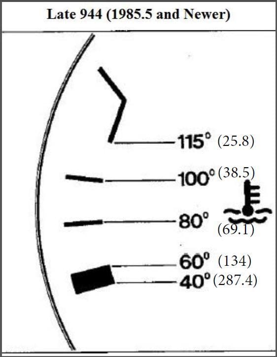
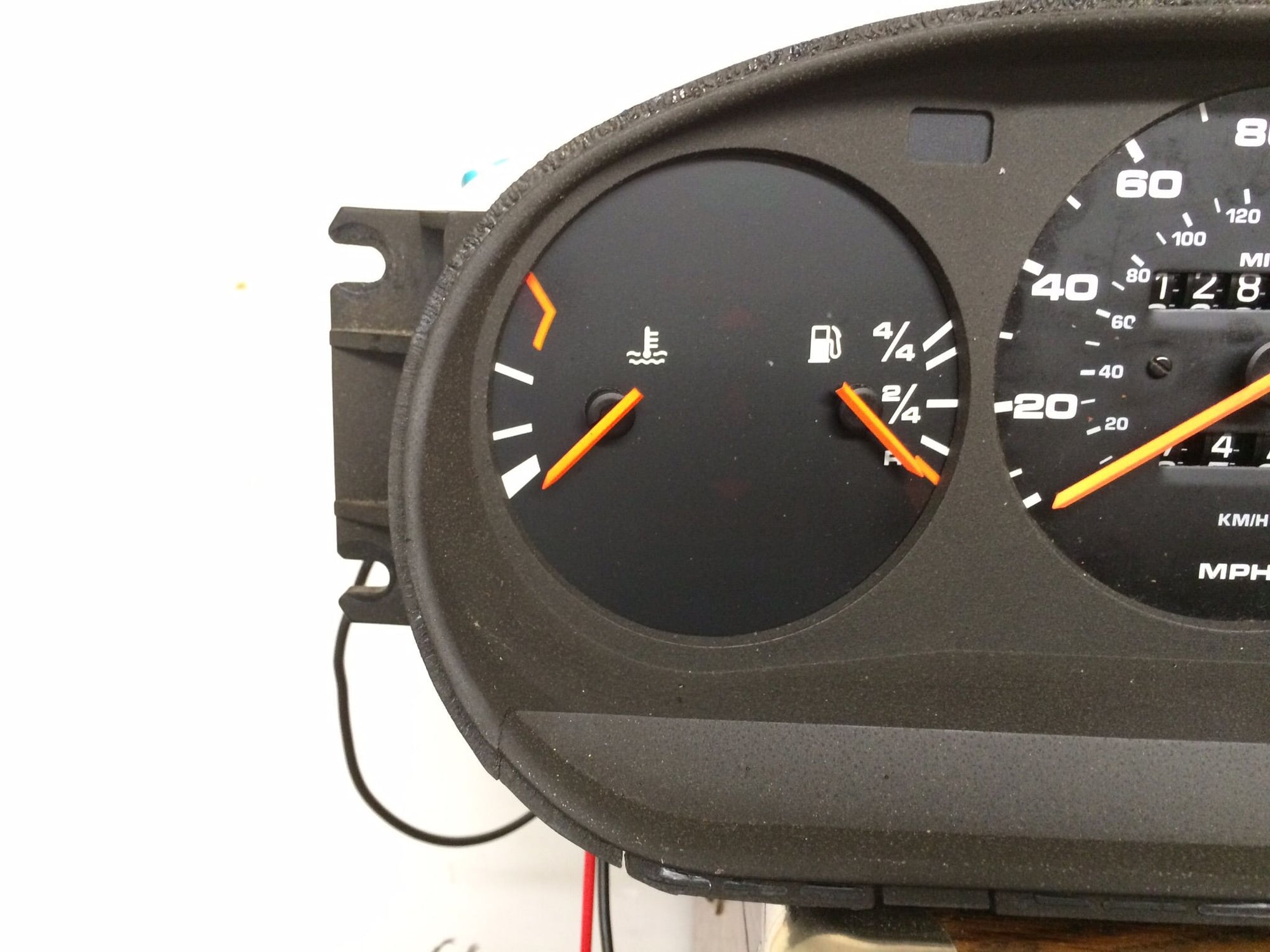
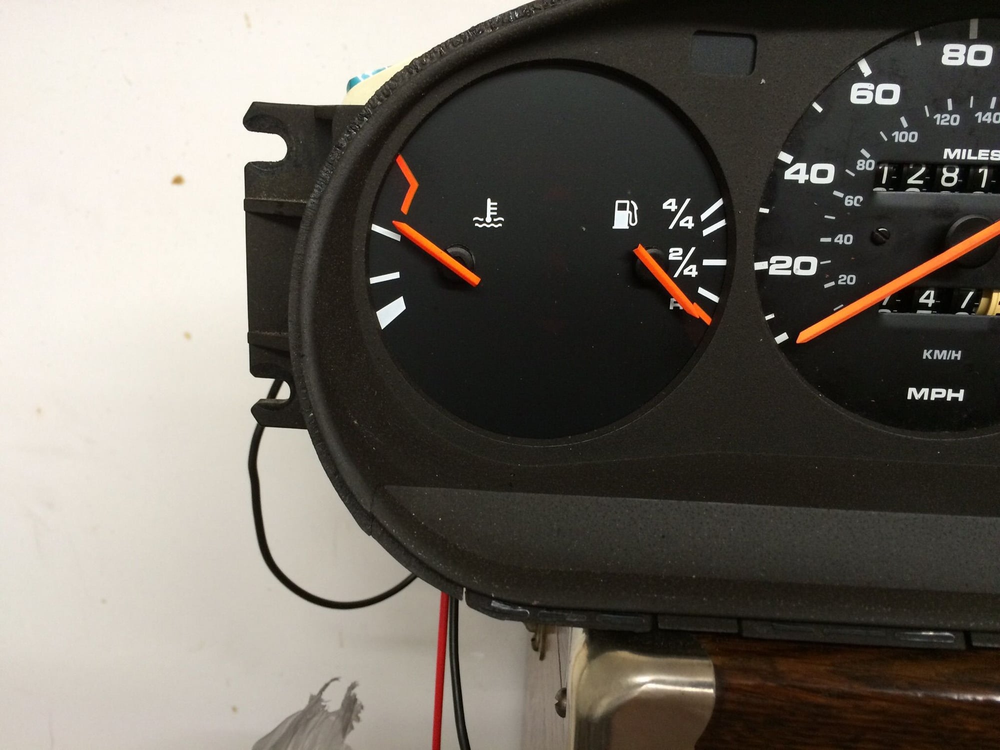
So, for the temp gauge, according to Clarks Garage, below is a picture of the temperatures and corresponding resistances needed at the sensor.
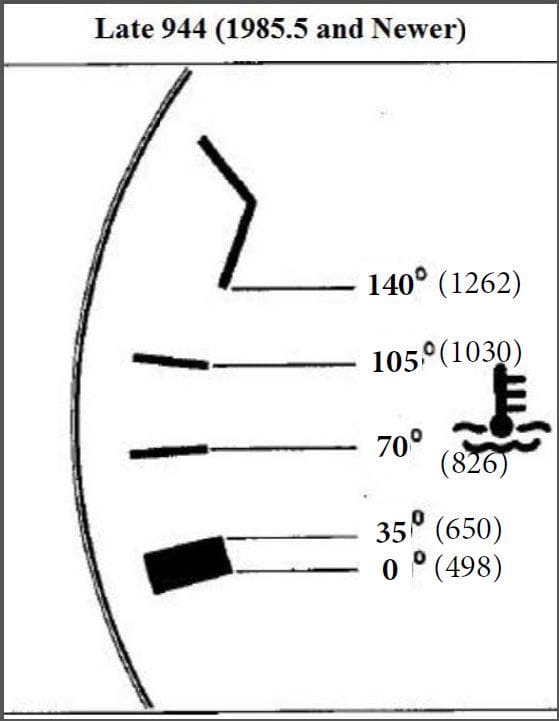
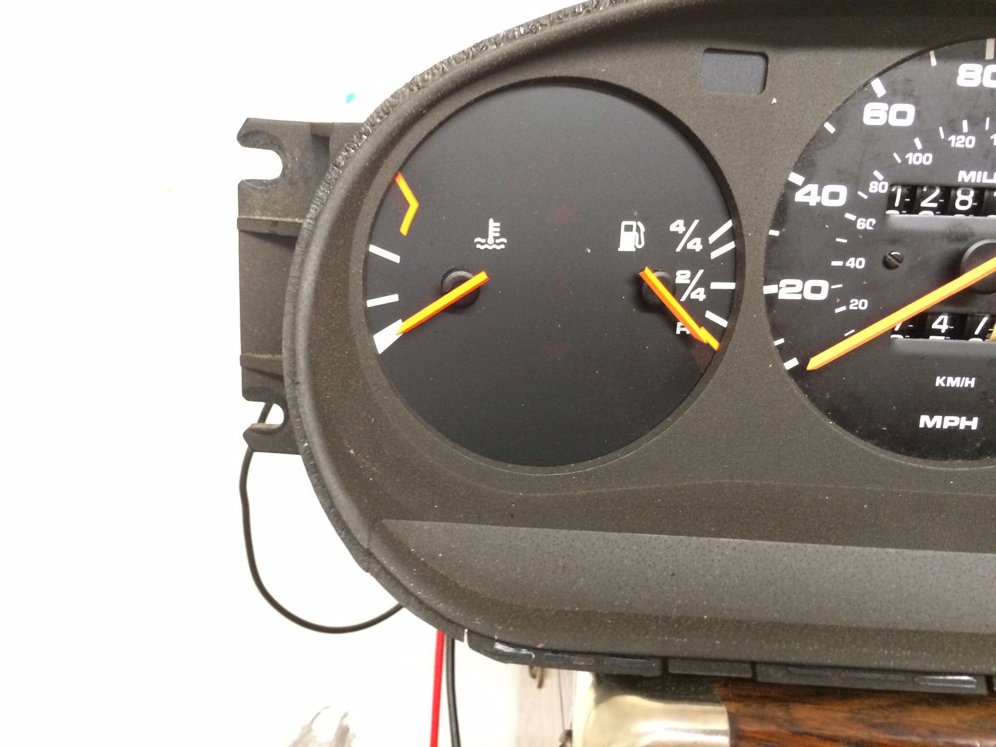
I discovered my electric motor actually has a thermistor in it (KTY84/130). Below is a modified picture of the temp gauge showing the resistances the thermistor would provide at the desired temperatures. Somehow I would have to develop a circuit that changed these resistances to match the factory picture above.
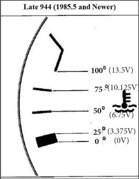
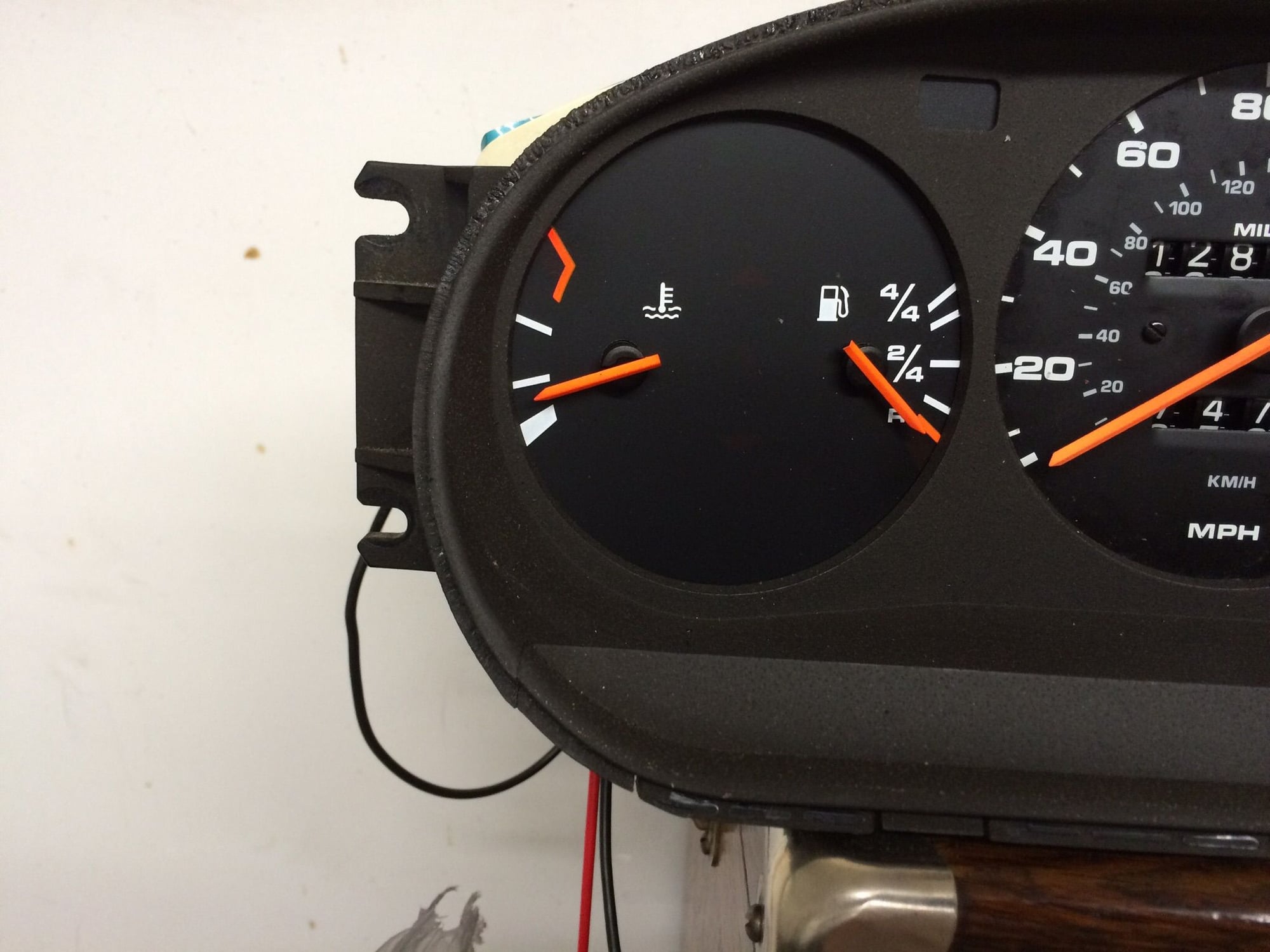
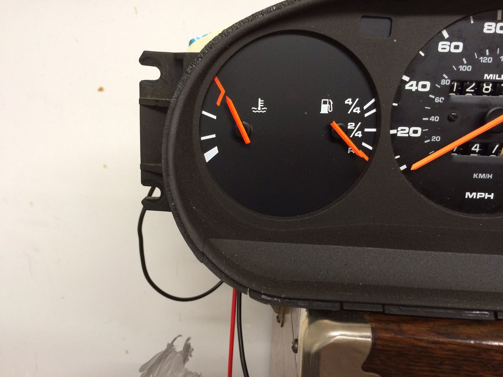
If I want to instead use the temperature of my controller (not sure yet which is more important, the controller or the motor temp), below is a modified picture of the temp gauge showing the voltages the controller would provide at the desired temperatures. Somehow I would have to develop a circuit that changed these voltages to match the resistances in the factory picture above.
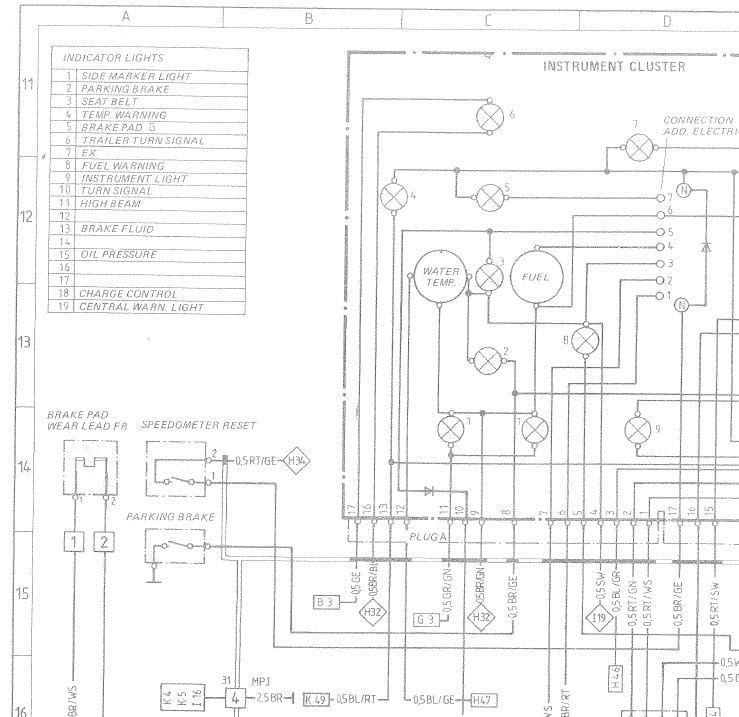
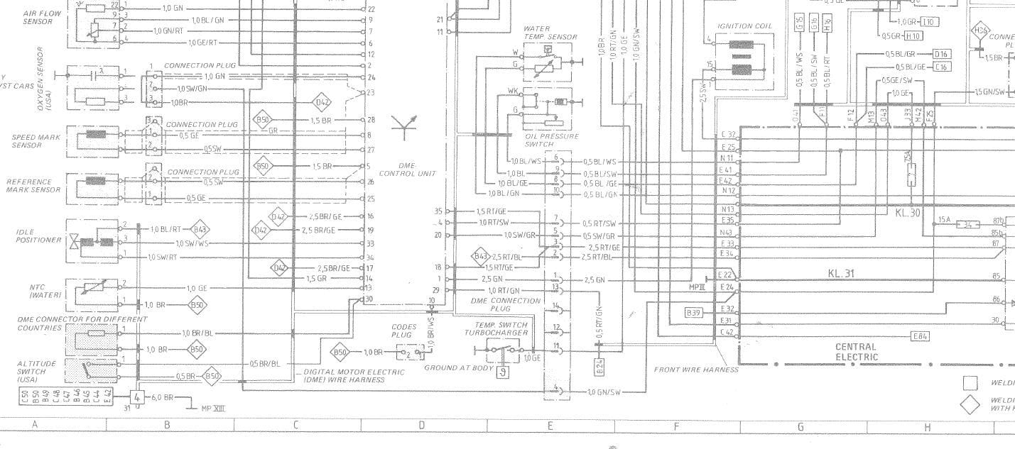
So all of the above is assuming the only way to control the temperature guage is to provide the necessary resistance at the connector specified in the Clarks Garage guides. I'm thinking there is a better way to take control of the gauge. From the below circuit diagrams, it looks like the temp gauge has 3 connections. The right connection is 12V from fuse 19 and the bottom connection is ground (MPII). The left connection confuses me a little...following the diagram, it looks like it goes to DME pin 8, then to the sensor, then to DME pin 10, then to the temperature indicator light, then to ground (the connection that goes to the light also goes to the AC Relay and Oil Pressure gauge??). However, I don't think it's actually DME pins 8/10, it looks like a 14 pin connector before the DME?? Also, pin 13 of the DME shows it is for a Temp Sensor. Can anyone shed some light on how this actually works?
That 8 is pin 8 on the 14 pin connector on the driver side firewall -- the one with the little black cover. From there is goes to the sensor -- follow the BL/GE wire all the way to the sensor in the diagram above.
The DME has it's own temp sensor in the head, the signal from which goes to DME pin 13. It's a different sensor and circuit from the temp gauge on the dash.
Have you used an Arduino before? They are remarkably easy to use, and with a few supporting components and a little ingenuity, it could translate your inputs and run both the fuel and temp gauge with one Arduino.
Never used an Arduino, but did do some programming on another micro controller (don't remember the brand) about 10 years ago.
I'd like to try to get the gauges working without one, but if I do end up using an Arduino, which one do you recommend?
For learning and starting out, you can't really beat the original Uno. It has headers for connecting wires and all the pins are marked nicely and line up with the "shields" (special purpose circuits) sold for the Arduino. Once you are comfy with that, you can go to a Nano or the teensy or just the processor by itself...
So I bought an Arduino, but haven't started playing with it yet, I wanted to first confirm how the gauges work. First up is the temp gauge since I've already started researching that one.
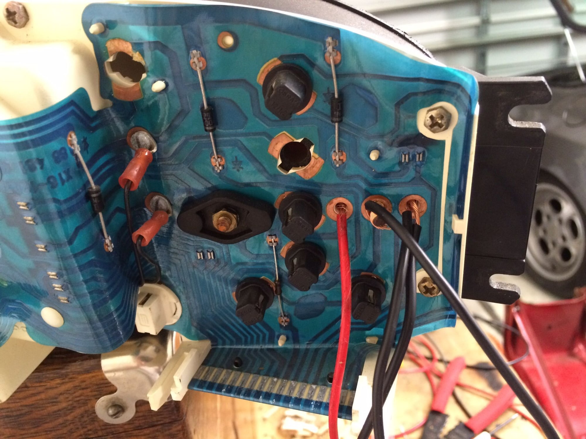
I took my gauge cluster out so I could interface directly with the gauge connections. In the car, the below pictured connections are 12V on the left pin, ground on the center pin, and variable resistance to ground on the right pin. Using this setup I was able to use a 1k potentiometer and control the gauge, and the resistance to reach each notch almost exactly match what was in Clarks Garage gauge troubleshooting (first picture in above post).
However, I don't know how I could recreate this variable resistance. Using the Arduino, I could control a digital potentiometer, but the only ones I can find are 5k and above. On top of that, the "resolution" is 8-bit, meaning there are 257 steps of different resistances from 0-5k, which means each step is about 19.5 ohms. This wouldn't work for me since the resistances needed are so low, so the steps are just too large.
This brings me back to how exactly does this gauge work...is it voltage driven or current driven? I connected the center and right pins to ground, and tried different voltages at the far left pin. I don't have a variable voltage supply, so I first started with different resistors between my 12.5V battery and the left pin, and eventually just used the 1k potentiometer so I could watch the gauge move. This worked, but it didn't seem very smooth. With the highest resistor, it would take a couple seconds for the gauge to move after connecting it. Also, using the pot I almost couldn't get the gauge to stop near the middle, it would just "jump" a rather large distance.
Any thoughts on how to correctly connect/control this gauge? How can I tell if it's voltage or current driven? If it helps, I measured the resistance of the gauge itself and it was 150 ohms from left pin to right pin...
I bet you can use a normal 10k digital pot by running a second fixed resistor in parallel. I've used the 41010 with the arduino (on other things) and it works well. The total resistance of two resistors in parallel is equal to (R1*R2)/(R1+R2). So if you have a 300 ohm resistor and a 10k resistor connected in parallel to ground, then the total resistance to ground is (300*10000)/(10300) or about 291 ohms. So�if you run a 300 ohm resistor to ground in parallel to a 10k digital pot, the total resistance will follow that formula as the digital pot is adjusted across its range (where R1 is always 300ohms, and R2 is whatever the pot is set to). If you work out the math, you�ll see that the total resistance will never exceed the fixed resistor, so you want to pick a fixed resistor a little higher than the highest resistance you need � in this case say 300. The total resistance increases logarithmically and approaches 300 as its mathematical limit. Your Arduino code just needs to incorporate that formula so that you can set the digital pot to the resistance needed to produce the desired total resistance. The fixed resistor will also reduce the current through the digital pot, which might increase your chance of not over-loading it (since they don�t like much current). No guarantees on this -- just my off the cuff reaction -- if you can't get it working let me know and I'll give it a try...
I bet you can use a normal 10k digital pot by running a second fixed resistor in parallel. I've used the 41010 with the arduino (on other things) and it works well. The total resistance of two resistors in parallel is equal to (R1*R2)/(R1+R2). So if you have a 300 ohm resistor and a 10k resistor connected in parallel to ground, then the total resistance to ground is (300*10000)/(10300) or about 291 ohms. So�if you run a 300 ohm resistor to ground in parallel to a 10k digital pot, the total resistance will follow that formula as the digital pot is adjusted across its range (where R1 is always 300ohms, and R2 is whatever the pot is set to). If you work out the math, you�ll see that the total resistance will never exceed the fixed resistor, so you want to pick a fixed resistor a little higher than the highest resistance you need � in this case say 300. The total resistance increases logarithmically and approaches 300 as its mathematical limit. Your Arduino code just needs to incorporate that formula so that you can set the digital pot to the resistance needed to produce the desired total resistance. The fixed resistor will also reduce the current through the digital pot, which might increase your chance of not over-loading it (since they don�t like much current). No guarantees on this -- just my off the cuff reaction -- if you can't get it working let me know and I'll give it a try...
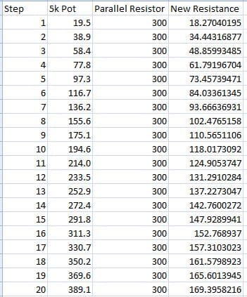
I actually had this exact same idea this morning, but then I put the numbers into an Excel spreadsheet and realized it's the exact opposite of what I need. Using the same 5k digital pot I mentioned above, and putting a 300 ohm resistor in parallel with it gives you almost the same large steps at the lower resistance range, and extremely small steps the closer you get to 300 ohms (see below).
.
.
.
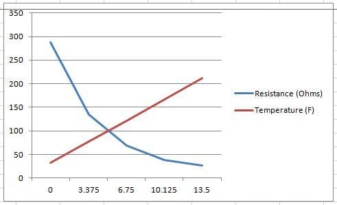
I need the opposite, with extremely small steps at lower resistances. Below is a graph showing what resistances I need to recreate as the temperature rises. X is the voltage the Soliton puts out for temperature...


 03-08-2015 | 11:37 PM