
Q for Electronics Techs --Boost Gauge Control!
 06-04-2008, 02:33 AM
#1
Rennlist Member
Thread Starter
In my on-going quest to hi-jack the factory boost guage, I confirmed the following tonight: the signal to the boost gauge comes from pin 5 of the KLR. At the KLR, with the gauge not connected, pin 5 varies from 0 to 5 volts. When the gauge is connected, pin 5 shows 0 to 1 volt. I take from this that the resistance in the gauge is 4 times the resistance behind pin 5 of the KLR, if that makes sense (based on my fuzzy understanding of voltage dividers). So... can I just feed a 0-5v signal to the gauge, or do I need to add a resistance behind the supply voltage. Assuming I need to add resistance, how can I determine how much is needed?
Last edited by Tom M'Guinn; 10-01-2018 at 01:07 PM.
 06-04-2008, 06:18 PM
#3
Burning Brakes
Join Date: Mar 2006
Location: Orlando,FL (formerly UK)
Posts: 1,215
Likes: 0
Received 0 Likes
on
0 Posts
...Are you quoting FSD or half-scale?
mind you I have to say that some meter circuits are CURRENT output and not voltage output. -Unless you know what the driver circuit is, you can't say for sure, because the voltage will climb in any current-drive circuit, as the load impedance rises, in order to 'force' the prescribed current through the load. -If you remove the load entirely and present something like a DVM as a load, the voltage will rise by a large amount in an effort to push the current through the high-resistance load.
So it depends. -The only way to test for a current drive is to measure the resistance of the dash meter (assuming that it's direct coupled to the DME output pin and that the other end goes to ground) and ADD the same resistance in series. -If it continues to operate normally, you have a current drive circuit, but if it reads 50% of the expected deflection at all times, then you have a simple voltage drive circuit.
If it's a voltage drive circuit, then your math is correct, and Kirchoff's law indicates that the source resistance is 4 times the load resistance.
Keith
06-05-2008, 12:04 AM
#5
Addict
Rennlist Member
Rennlist Member

Join Date: Feb 2002
Posts: 5,384
Likes: 0
Received 0 Likes
on
0 Posts
Try this.
From your boost driver(0-5V), add a 1.9K resistor in series to a 2K resistor. The output of the 2K goes to the gauge. Add a 0.47uF cap to the junction of the two resistors and the other end of the cap to ground. With a 2.5V input from your boost driver, you should see 1 bar on the gauge. Were did this come from? This is what is inside the KLR.
From your boost driver(0-5V), add a 1.9K resistor in series to a 2K resistor. The output of the 2K goes to the gauge. Add a 0.47uF cap to the junction of the two resistors and the other end of the cap to ground. With a 2.5V input from your boost driver, you should see 1 bar on the gauge. Were did this come from? This is what is inside the KLR.
06-05-2008, 12:24 AM
#6
Rennlist Member
Thread Starter
Kevin: I am working to disconnect the factory boost gauge from the DME, and supply my own signal to it, so that I can have the gauge read from 0psi on the left to 30psi on the right. I will either print a sticker showing 0 to 30psi for the gauge, or have someone print a new faceplate for it. My plan is to put a little trim pot in the circuit so that it can be calibrated for accuracy.
VWa: Thanks for those thoughts. I did more testing tonight, and did gain control over the gauge. It appears the gauge is driven by voltages. The gauge itself has about 1K resistance, meaning a 0-5 volt boost signal needs about a 4k resistor in order for the 0-5vdc signal to sweep the gauge from left to right. If I run 5vdc through a 4k resistor, the gauge reads 2 bar. If I run 5vdc through a 9k resistor, the gauge reads 1 bar, which all seems to be consistent with the 1k resistance of the gauge itself. Tomorrow, I'll put a 4k resistor on a variable 0-5 signal and confirm it works properly across the full 0 to 5 volt range. See any flawed logic by this non-electronics tech?
VWa: Thanks for those thoughts. I did more testing tonight, and did gain control over the gauge. It appears the gauge is driven by voltages. The gauge itself has about 1K resistance, meaning a 0-5 volt boost signal needs about a 4k resistor in order for the 0-5vdc signal to sweep the gauge from left to right. If I run 5vdc through a 4k resistor, the gauge reads 2 bar. If I run 5vdc through a 9k resistor, the gauge reads 1 bar, which all seems to be consistent with the 1k resistance of the gauge itself. Tomorrow, I'll put a 4k resistor on a variable 0-5 signal and confirm it works properly across the full 0 to 5 volt range. See any flawed logic by this non-electronics tech?
06-05-2008, 12:29 AM
#7
Rennlist Member
Thread Starter
Try this.
From your boost driver(0-5V), add a 1.9K resistor in series to a 2K resistor. The output of the 2K goes to the gauge. Add a 0.47uF cap to the junction of the two resistors and the other end of the cap to ground. With a 2.5V input from your boost driver, you should see 1 bar on the gauge. Were did this come from? This is what is inside the KLR.
From your boost driver(0-5V), add a 1.9K resistor in series to a 2K resistor. The output of the 2K goes to the gauge. Add a 0.47uF cap to the junction of the two resistors and the other end of the cap to ground. With a 2.5V input from your boost driver, you should see 1 bar on the gauge. Were did this come from? This is what is inside the KLR.
Trending Topics
06-05-2008, 12:42 AM
#8
Addict
Rennlist Member
Rennlist Member
Join Date: Feb 2002
Posts: 5,384
Likes: 0
Received 0 Likes
on
0 Posts
I am just datalogging the boost data. I use it to look for spikes and to see if it is rising. So far, it has been really solid. I was going over my boost data that I sent to Kevin and saw that the scales on the log file were incorrect. I had it setup for a range of 0-2.5 volts and selected the 5 volt input scale. It logged the 0-2.5 volt signal but the right scale was 0-5 volts so all the values were 2x. Bug in the software.
Your post got me going and I traced out a spare KLR I have laying around. I came to the exact result you did, 1V is one bar boost. I am going to pull a spare gauge this weekend and really spend some time calibrating it. I am a little confused why my voltage with ignition on (one bar on the meter) is a little under 0.5V. Could be the difference above sea level.
BTW: The cap in the circuit is a low pass filter and gives the meter a smother response.
06-05-2008, 01:01 AM
#9
Rennlist Member
Thread Starter

If you are asking why it is not exactly .5v, I would chalk it up to all the reasons the factory gauge is not spot accurate in the first place.
06-05-2008, 01:14 AM
#10
Addict
Rennlist Member
Rennlist Member
Join Date: Feb 2002
Posts: 5,384
Likes: 0
Received 0 Likes
on
0 Posts
Yup, I get around 0.45 volts and I expected 0.5 volts. It looks like the preasure sensor in the KLR is a good unit, at least it looks like it was expensive to make in its day. I was expecting the voltage to be accurate, not sure about that little factory gauge.
06-05-2008, 01:28 AM
#11
Three Wheelin'
Kevin: I am working to disconnect the factory boost gauge from the DME, and supply my own signal to it, so that I can have the gauge read from 0psi on the left to 30psi on the right. I will either print a sticker showing 0 to 30psi for the gauge, or have someone print a new faceplate for it. My plan is to put a little trim pot in the circuit so that it can be calibrated for accuracy.
That's a very cool project, I'm sure that you can make it accurate enough. When I looked into custom gauge faces a while back it was less than $20 for someone to print a sheet of multiples. If you do that and make some kind of little border it could look stock if that's what you're after. Good luck and post some pics
 06-05-2008, 01:38 AM
#12
Rennlist Member
Thread Starter
[QUOTE=kevincnc;5480352]
Right, my thought was to make it look stock, so you'd think they built it that way unless you knew better. We'll see how I do -- it's been a back-burner idea for a long time.
Kevin: I am working to disconnect the factory boost gauge from the DME, and supply my own signal to it, so that I can have the gauge read from 0psi on the left to 30psi on the right. I will either print a sticker showing 0 to 30psi for the gauge, or have someone print a new faceplate for it. My plan is to put a little trim pot in the circuit so that it can be calibrated for accuracy.
That's a very cool project, I'm sure that you can make it accurate enough. When I looked into custom gauge faces a while back it was less than $20 for someone to print a sheet of multiples. If you do that and make some kind of little border it could look stock it that's that you're after. Good luck and post some pics
That's a very cool project, I'm sure that you can make it accurate enough. When I looked into custom gauge faces a while back it was less than $20 for someone to print a sheet of multiples. If you do that and make some kind of little border it could look stock it that's that you're after. Good luck and post some pics
06-05-2008, 10:19 AM
#13
Burning Brakes
Join Date: Mar 2006
Location: Orlando,FL (formerly UK)
Posts: 1,215
Likes: 0
Received 0 Likes
on
0 Posts
When you say Zero psi on the left and 30psi on the right, do you mean zero psi above atmostpheric, or zero psi absolute vacuum? -Just curious...
That capacitor in between the 2k and the 1.9k resistances is acting as a ripple filter, to damp out any ripple fluctuations and save the meter from trying to respond to insignificant flutter. -Since ripple or 'flutter' isn't something that we're interested in, and it places a disporoportionate mehanical and electrical load on the meter (because the meter has a strong inductive component above and beyond the resistive component) there's some significant long-term wear benefit from including the capacitance.
Keith
06-05-2008, 10:26 AM
#14
Burning Brakes
Join Date: Mar 2006
Location: Orlando,FL (formerly UK)
Posts: 1,215
Likes: 0
Received 0 Likes
on
0 Posts
By the way I've printed my own meter scales onto metal before.
Here's a picture of a recent prototype item which I built, where I printed the front panel markings and the meter scale...
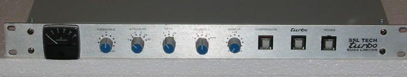


....And of course I named the project "turbo!"

It's pretty easy to do... you just need some 3M super 77 adhesive, some adhesive-release backing paper (like the stuff that you peel off from "laser labels" and usually throw away... -basically think of it as being almost free!) and a laser printer. -In this case, I shot some clearcoat over the finished panel, to make it scratch and abuse-resistant, but you don't HAVE to, and the finished thing can look very stock indeed.
Keith
Here's a picture of a recent prototype item which I built, where I printed the front panel markings and the meter scale...
....And of course I named the project "turbo!"
It's pretty easy to do... you just need some 3M super 77 adhesive, some adhesive-release backing paper (like the stuff that you peel off from "laser labels" and usually throw away... -basically think of it as being almost free!) and a laser printer. -In this case, I shot some clearcoat over the finished panel, to make it scratch and abuse-resistant, but you don't HAVE to, and the finished thing can look very stock indeed.
Keith
06-05-2008, 11:33 AM
#15
Rennlist Member
Thread Starter
When you say Zero psi on the left and 30psi on the right, do you mean zero psi above atmostpheric, or zero psi absolute vacuum? -Just curious...
That capacitor in between the 2k and the 1.9k resistances is acting as a ripple filter, to damp out any ripple fluctuations and save the meter from trying to respond to insignificant flutter. -Since ripple or 'flutter' isn't something that we're interested in, and it places a disporoportionate mehanical and electrical load on the meter (because the meter has a strong inductive component above and beyond the resistive component) there's some significant long-term wear benefit from including the capacitance.
Keith
That capacitor in between the 2k and the 1.9k resistances is acting as a ripple filter, to damp out any ripple fluctuations and save the meter from trying to respond to insignificant flutter. -Since ripple or 'flutter' isn't something that we're interested in, and it places a disporoportionate mehanical and electrical load on the meter (because the meter has a strong inductive component above and beyond the resistive component) there's some significant long-term wear benefit from including the capacitance.
Keith