When you click on links to various merchants on this site and make a purchase, this can result in this site earning a commission. Affiliate programs and affiliations include, but are not limited to, the eBay Partner Network.
I was digging through my pile of VW - Audi parts and came across this set of coils that fit pretty flush with the valve cover . They are not the pretty red versions , but I ran a straight edge across it and compared the height difference , almost 15mm shorter than the 07k ones . All I did was shorten the rubber boot on these as well .
I was digging through my pile of VW - Audi parts and came across this set of coils that fit pretty flush with the valve cover . They are not the pretty red versions , but I ran a straight edge across it and compared the height difference , almost 15mm shorter than the 07k ones . All I did was shorten the rubber boot on these as well .
Oh sweet, I'm going to have to look into those. Looks like part number 06A 905 115 D is from a B5 or B6 A4 1.8T (among others).
I bolted it back on lastnight to show just what all I cut back .
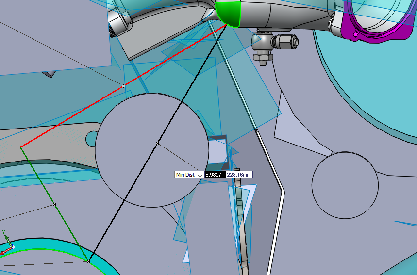
I think you nailed it! My measurements in CAD show that the bottom of the intake manifold is about 9 inches from the crank pulley (measured radially out from the tips of the ribs). I think that round boss that you shaved the accessory bracket down to is about 8-1/2 inches.
Quick unit conversion... 10 MPa = 10 N/mm^2 = 1450 lb/in^2 (psi), should be more than enough to turn some wheels. After all, these are the same things they use for dump trailers... The only problem now is finding an ESC for the motor to control it so that it's not too sensitive at high speeds and powerful enough for parking at low speeds. Another tap into the rear transmission speed signal paired with a microcontroller with a linear progression "for loop" would probably do the trick.
i was thinking it could be tied to some kind of speed sensor to only work at <25mph or so.
a depowered 944 rack is very light once you're moving so you could get away just by shutting the pump off until you're going slow.
maybe this should be its own thread rather than continuing here though?
i was thinking it could be tied to some kind of speed sensor to only work at <25mph or so.
a depowered 944 rack is very light once you're moving so you could get away just by shutting the pump off until you're going slow.
maybe this should be its own thread rather than continuing here though?
Good point. I'll probably make a thread this summer outlining my attempt at it.
I just added another note to the installation pointers:
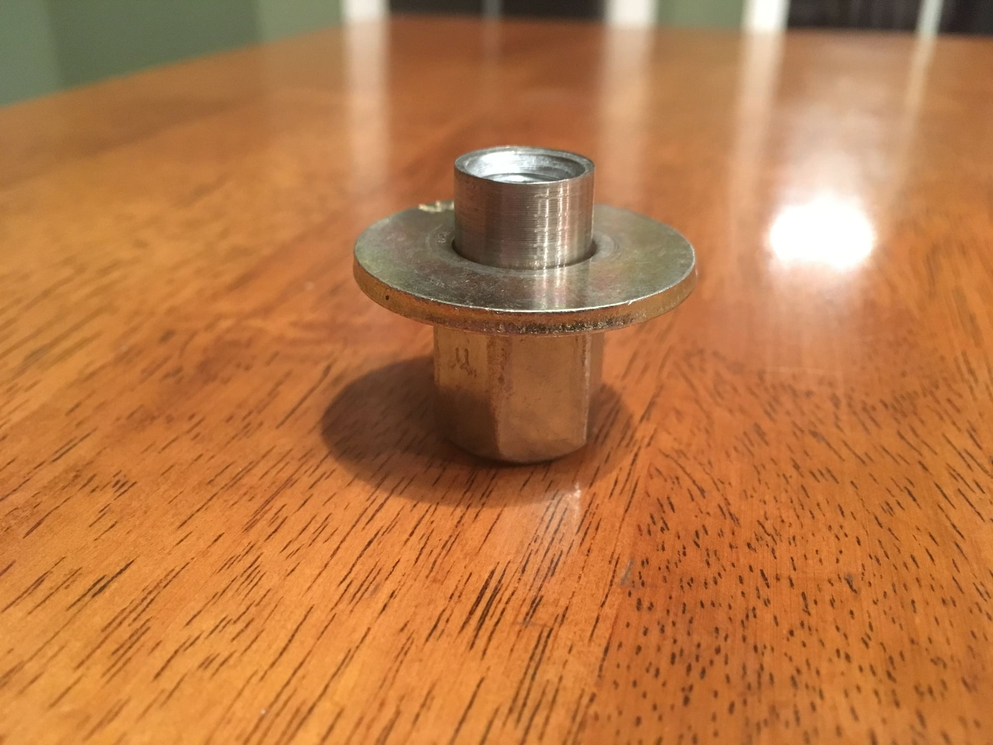
8. You will notice some "unique" nuts on the bottom of engine mount isolators. These are custom made from high strength (grade 10.9) coupling nuts. They were necessary due to the funky shaped underside of the stock cross member casting. I recommend torquing them in the range of 45-50 ft-lb, which is the recommended torque spec for a M10 grade 10 fastener. If you torque them way over that it is possible to break them off at the base of the turned down feature (I found them to yield around 80-90 ft-lb, which is way over-torqued for an M10). I plan to use Loctite blue threadlocker as well.
Bellhousing drawings are finally released! Getting parts for one made asap to test fit.
While that's being made, I'll work on buttoning up the intake manifold design next, so I can get the tooling and prototype on order. I need to add a few features to hold the throttle cable for a VR6 TB. And I'm going to angle the injectors slightly different so that they match the OE manifold angle.
Slow progress... but progress nonetheless. :-) Thanks again everyone for your patience.
Progress is progress. Love seeing the solutions you guys are coming up with. Hard not to want to ask a bunch of questions, but I know with due time, the answers will come regardless.
Really thinking about just listing the head and cam package I have here for my stock motor up for sale at this point. Excited to see what ends up being the answer for the coolant port issues. I mean. If I gotta cut a bit of a firewall and fab in a bit of new sheet metal, Im sure I can figure it out, but if its avoidable, I'd prefer it haha
With the amount of time and energy Alan put into making the stock hood fit without dropping the crossmember, I�m sure we can find a solution that doesn�t require cutting the firewall! Then again, I�m not the engineer haha.
I had a simple idea until I found all the different steps in the back of the factory flange . I don’t have direct access to a milling machine so I can’t machine out all the necessary steps . This is a basic concept I had , machine out the flange and add a stem on it like the CP-S version , overall length from flange face to the top of the stem 1.25” . Notch the stem ( like notching a roll cage tube ) and weld an 1.25” section of tubing parallel to the head like in my first pic , bore from the inside of the flange . Add a bung to the short end for the heater hose . Add whatever bungs to the long side for sensors . Add a mounting tab to the long end to relieve stress .
I had a simple idea until I found all the different steps in the back of the factory flange . I don�t have direct access to a milling machine so I can�t machine out all the necessary steps . This is a basic concept I had , machine out the flange and add a stem on it like the CP-S version , overall length from flange face to the top of the stem 1.25� . Notch the stem ( like notching a roll cage tube ) and weld an 1.25� section of tubing parallel to the head like in my first pic , bore from the inside of the flange . Add a bung to the short end for the heater hose . Add whatever bungs to the long side for sensors . Add a mounting tab to the long end to relieve stress .
For someone with the right equipment, this looks doable, I think I get what you're saying.
Wish I was a metal fabricator so badly, somedays. I'd buy the kit just to help out with figuring stuff out.


 02-03-2019, 08:39 PM