

Need help - Vitesse MAF Fitment
 05-09-2009, 06:29 PM
#1
Odd Posts
Rennlist Member
Rennlist Member
Thread Starter
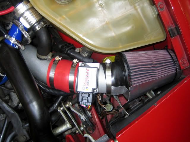
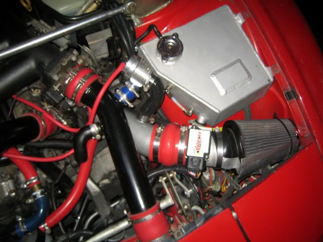
Doing the DIY install of my new Vitesse MAF. I think I am almost there, but as seen in the picture below the fitment is still not quite correct. I would greatly appreciate tips and thoughts on achieving the type of fitment that I see in the various pictures in the forum.
I think the problem is two-fold (1) I am running a K26/6 turbo and the reducer coupling makes the overall assembly a little longer and (2) I may not have the angles quite right.
Finally, I seem to have an extra vacuum line (from the cycling valve?) circled in green. Not sure what to do with this one as there are not enough connection points on the MAF J-Pipe. Any ideas?
Thanks
 05-09-2009, 08:38 PM
#2
Nordschleife Master
Fergus, where exactly are you having trouble with the fitment of the MAF? Looks like you have it on most of the way, just make sure you can shut the hood without the headlight propping up and the headlight cycles properly.
In my personal experience so far there is no way to avoid the air filter sitting cocked on the MAF housing, like the way you have it in the pictures. Mine is the same way. If you find the housing is still too long, cut down the reducer on the K26/6 end to reduce the length. I had to do this on mine when i used a reducer with the K26.
One thing that helped alot was using a 3'' hump coupler inbetween the j-pipe and MAF housing. This gives some much needed flex to help align the filter more evenly on the MAF meter.
Dont have anything to tell you about the lack of fitting for the CV, my guess is most people run manual boost controllers at this point.
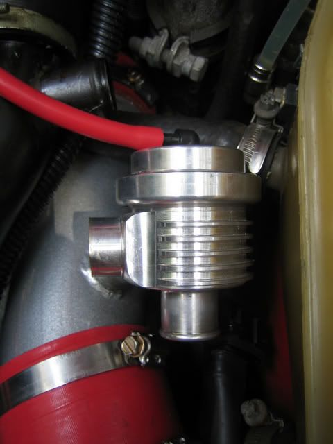
The most challenging part for me was fitting the bypass valve. I bought some 19mm 90* silicone elbows (pretty sure it was 19..double check that) and had to cut off the barbed end of the bypass valve.
Here are a bunch of pictures from the many different 'stages / configurations' i used when fitting the MAF and bypass valve. Hopefully they are helpful for you.
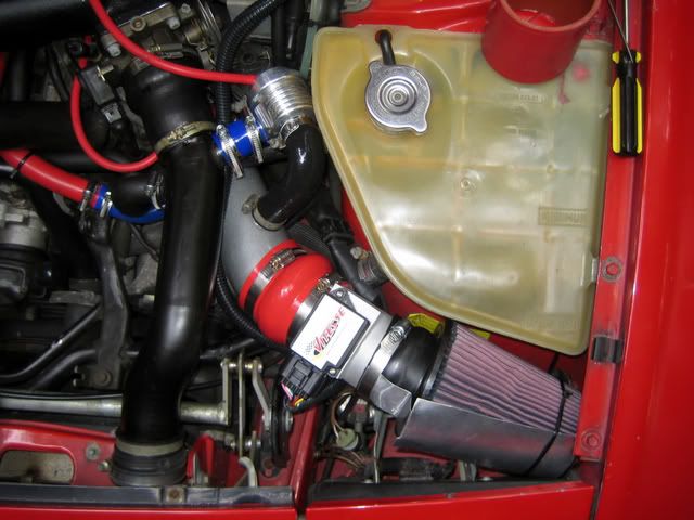
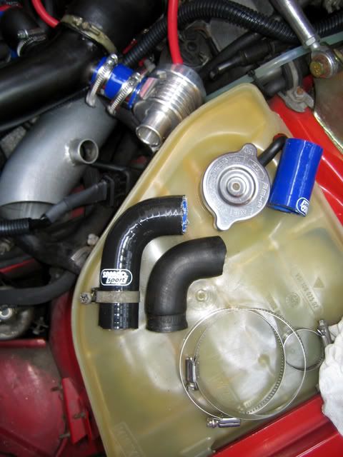
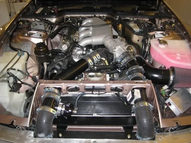
With supplied 3'' coupler, note air filter being crooked on meter and bypass valve fitment (line kinked).
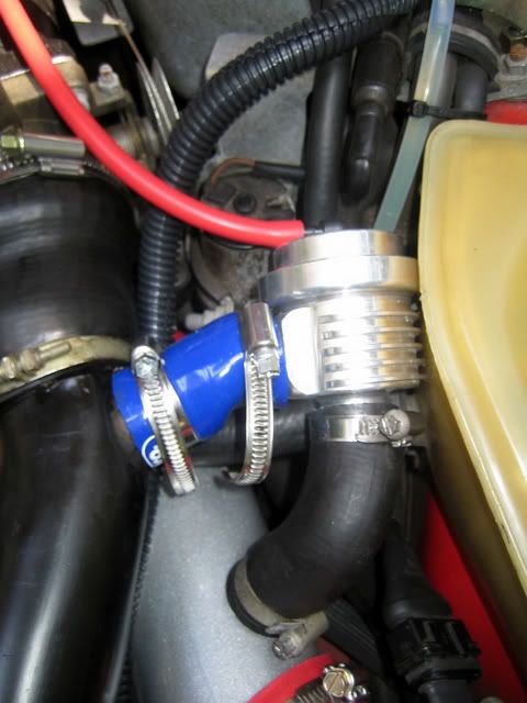
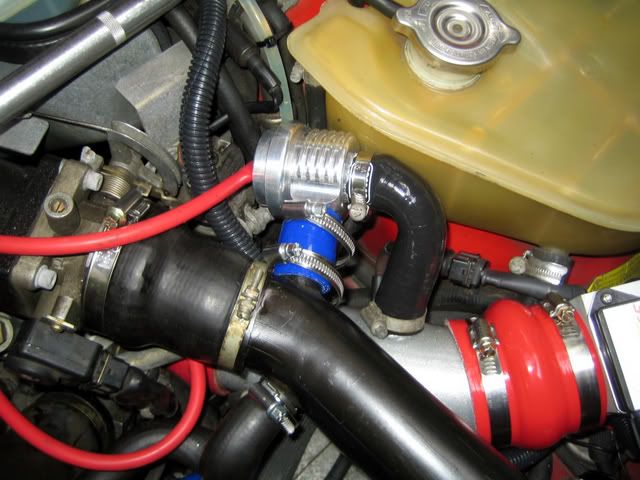
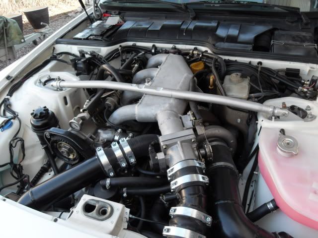
With 3'' hump coupler and better bypass valve fitment (more on that below). Note this is with the stock intercooler pipes. When i put the LR pipes on, i had to do further fitment (mostly trimming) to get the bypass valve to sit right because the barbs are in slightly different places.
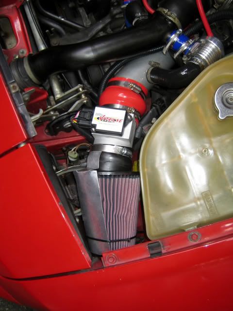
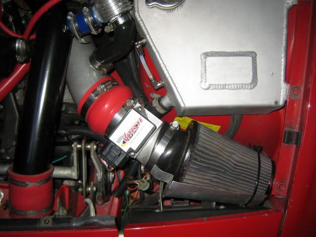
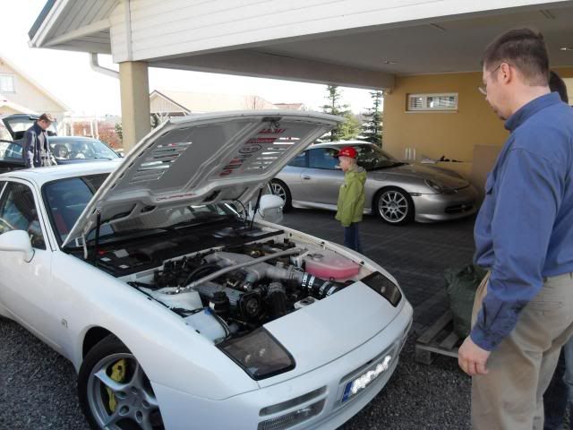
And here is fitment as it stands today with a bigger turbo, 2.75'' - 3'' reducer.
In my personal experience so far there is no way to avoid the air filter sitting cocked on the MAF housing, like the way you have it in the pictures. Mine is the same way. If you find the housing is still too long, cut down the reducer on the K26/6 end to reduce the length. I had to do this on mine when i used a reducer with the K26.
One thing that helped alot was using a 3'' hump coupler inbetween the j-pipe and MAF housing. This gives some much needed flex to help align the filter more evenly on the MAF meter.
Dont have anything to tell you about the lack of fitting for the CV, my guess is most people run manual boost controllers at this point.
The most challenging part for me was fitting the bypass valve. I bought some 19mm 90* silicone elbows (pretty sure it was 19..double check that) and had to cut off the barbed end of the bypass valve.
Here are a bunch of pictures from the many different 'stages / configurations' i used when fitting the MAF and bypass valve. Hopefully they are helpful for you.
With supplied 3'' coupler, note air filter being crooked on meter and bypass valve fitment (line kinked).
With 3'' hump coupler and better bypass valve fitment (more on that below). Note this is with the stock intercooler pipes. When i put the LR pipes on, i had to do further fitment (mostly trimming) to get the bypass valve to sit right because the barbs are in slightly different places.
And here is fitment as it stands today with a bigger turbo, 2.75'' - 3'' reducer.
05-09-2009, 09:22 PM
#3
Addict
Rennlist Member
Rennlist
Site Sponsor
Rennlist Member
Rennlist
Site Sponsor
Fergus, The picture looks fine, just adjust for clearance. You can angle the MAF at the J-pipe a bit, this will reduce the angle between the MAF & Filter.
For the BOV, use the hose I sent you (might need to trim it), have the BOV tilt toward the front a bit, then use the stock "L" hose.
The extra vacuum hose is the return line for the cycling valve, which you need to bypass and use a different boost controller. If you do want to keep the CV, just "T" this line to the line at the back of the J-pipe.
BTW. I just replied to your email.
05-09-2009, 09:41 PM
#4
Odd Posts
Rennlist Member
Rennlist Member
Thread Starter
Jon - Thanks for the detailed reply. That helps enormously, I thought that I was missing something due to my limited experience. I do not feel like a dunce anymore
John, thanks I will check shortly.
John, thanks I will check shortly.
05-10-2009, 10:08 AM
#6
Basic Sponsor
Rennlist
Site Sponsor
Rennlist
Site Sponsor
Fergus... noticed in your 2nd picture you have your Idle Stabalizer hose connected to your
MAF tree. Or at least it looks that way in the picture. That's going to have to get switched
or you will never be happy with how it runs.
MAF tree. Or at least it looks that way in the picture. That's going to have to get switched
or you will never be happy with how it runs.
__________________
Mike or Dave Lindsey
www.lindseyracing.com
U.S. 1-877-943-3565
Other 1-405-947-0137
Mike or Dave Lindsey
www.lindseyracing.com
U.S. 1-877-943-3565
Other 1-405-947-0137
05-10-2009, 11:14 AM
#7
Odd Posts
Rennlist Member
Rennlist Member
Thread Starter
Dan, it is in the future, just not the immediate future I need to read up to understand how to connect etc. My cycling valve in brand new and I have LBE, so given that I have now busted the annual improvement budget (and the wideband is still to go in), it will be a future project.
Mike, I think it is just the picture. I do not have anything connected to the tree yet.
I need to read up to understand how to connect etc. My cycling valve in brand new and I have LBE, so given that I have now busted the annual improvement budget (and the wideband is still to go in), it will be a future project.Mike, I think it is just the picture. I do not have anything connected to the tree yet.
Trending Topics
 05-10-2009, 01:18 PM
#9
Instructor

I ask because I have my stabilizer hose connected to the maf tree spot and am having trouble with the engine dying at stops if I don't let the rpms drop real slow.
05-10-2009, 02:30 PM
#10
Nordschleife Master
The idle stabilizer hose should connect to the intercooler pipe. The MAF tree connection should get the crankcase vent from the air oil separator.
05-10-2009, 02:40 PM
#12
Odd Posts
Rennlist Member
Rennlist Member
Thread Starter
Why not install Vitesse MAF like Pete did it
The picture does not seem to want to display. Can you please repost? Thanks
05-10-2009, 03:53 PM
#13
Instructor
 . Mine is hooked up correctly (better be since I followed the directions to the letter)
 05-10-2009, 04:05 PM
#14
Rainman
Rennlist Member
Rennlist Member
is that the same type of valve on like a supercoupe, a bypass valve? on part throttle (with low vacuum) it opens to let air bypass the compressor and go straight into the intake? and then closes on full throttle (high vacuum) to let the turbo do its thing?
