

HELP!! Car running terrible after new vac. lines and venturi delete
 05-14-2007, 07:23 PM
#1
Racer
Thread Starter

Join Date: Apr 2006
Location: Raleigh, NC
Posts: 364
Likes: 0
Received 0 Likes
on
0 Posts
So heres the story. This weekend I pulled off the intake manifold to do a bunch of things. I installed my Lindsey black **** MBC, deleted the cycling valve, replaced the vacuum lines, and did a venturi delete with lindsey's kit. I put everything back together this morning and started up the car.
It starts up alright, but it runs really really rough. It almost seems like one of the cylinders is not firing. I checked the spark plug wires and they all are seated correctly.
I ran a 3/4inch radiator hose from the J-boot to the AOS, unplugged and pulled the cycling valve out, ran the new vacuum lines according to lindsey's diagram, and used my new lindsey hoses to connect the ISV to the manifold and throttle body intercooler pipe.
I dont know what could be causing the car to run this rough. Would a vacuum leak cause it to run really rough? On my boost gauge I was getting about 13-14mm/hg vacuum and the car was cold, from what I've read that seems pretty normal/healthy.
My dad took a look at the car and thinks something is wrong with the timing. Is there any way I could have messed with the timing by just removing the intake manifold and doing the normal vac. lines and venturi delete?
Could running the hoses to my boost controller incorrectly be causing this big a problem?
I'm just trying to rule things out but I really am confused.
Hopefully someone can give me some insight or something else to check for because I really need the car to be running right. Thanks guys
Last edited by 5speed300; 05-22-2007 at 04:59 PM.

 05-14-2007, 08:18 PM
#4
Racer
Thread Starter
Join Date: Apr 2006
Location: Raleigh, NC
Posts: 364
Likes: 0
Received 0 Likes
on
0 Posts
Ski,
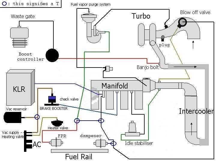
I'm having trouble reading that diagram because it leaves out the brake booster T and shows 4 lines coming off the intake manifold banjo bolt where I only have two.
I have followed the following diagram from lindsey...
The only difference is I have removed all of the GREEN lines related to the CV.
Am I missing something by following this diagram due to my using a boost controller?
Instead of the green lines shown in this diagram, I have a line running from the intercooler banjo bolt into my boost controller, and then a line running out of the boost controller and into the top of the wastegate (I'm running in single port mode)
05-14-2007, 08:20 PM
#5
Racer
Thread Starter
Join Date: Apr 2006
Location: Raleigh, NC
Posts: 364
Likes: 0
Received 0 Likes
on
0 Posts
Originally Posted by dime1622
Check that the intake manifold is properly seated back down.
05-14-2007, 08:27 PM
#6
i don't think it's causing your problem, but usually the black-**** style MBC is meant for a dual port wastegate in dual port mode. i don't think it'll work with a single port.
Trending Topics
05-14-2007, 08:34 PM
#8
Racer
Thread Starter
Join Date: Apr 2006
Location: Raleigh, NC
Posts: 364
Likes: 0
Received 0 Likes
on
0 Posts
I could also follow this vacuum line diagram as it shows the venturi delete and single port MBC install. I just dont understand what happens to the T in the brake booster to intake manifold? Its not shown here so what do I do with it?
05-14-2007, 09:11 PM
#10
Racer
Thread Starter
Join Date: Apr 2006
Location: Raleigh, NC
Posts: 364
Likes: 0
Received 0 Likes
on
0 Posts
Here are a few pictures so you guys can see my setup.
I think my problem may lie somewhere in the blue circled area, does this setup look right to you?
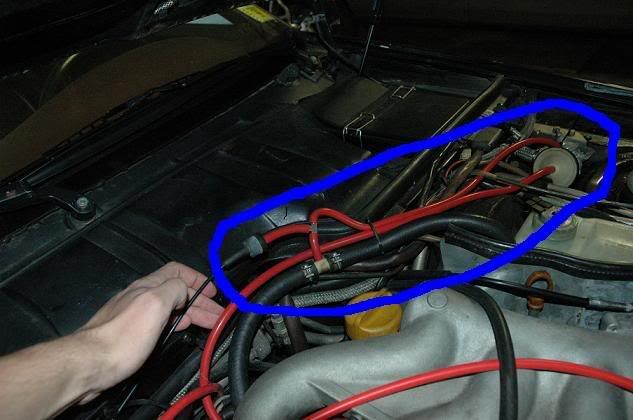
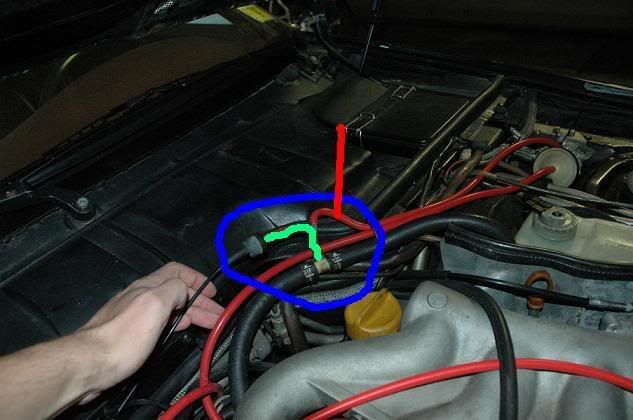
From looking at diagrams, should the line with the RED line coming off of it be connected to a T from the intake manifold banjo bolt? And in that case should the blue/black thing connect straight to the brake T as the green line shows?
I think my problem may lie somewhere in the blue circled area, does this setup look right to you?
From looking at diagrams, should the line with the RED line coming off of it be connected to a T from the intake manifold banjo bolt? And in that case should the blue/black thing connect straight to the brake T as the green line shows?
05-14-2007, 09:49 PM
#11
Originally Posted by 5speed300
Ski,
I'm having trouble reading that diagram because it leaves out the brake booster T and shows 4 lines coming off the intake manifold banjo bolt where I only have two.
I have followed the following diagram from lindsey...
The only difference is I have removed all of the GREEN lines related to the CV.
Am I missing something by following this diagram due to my using a boost controller?
Instead of the green lines shown in this diagram, I have a line running from the intercooler banjo bolt into my boost controller, and then a line running out of the boost controller and into the top of the wastegate (I'm running in single port mode)
Whoa, stop a sec.
You removed all of the green hoses? Did you plug the hole in the j-boot (or MAF piping)?
PS. your pics above look fine
05-14-2007, 10:06 PM
#12
Racer
Thread Starter
Join Date: Apr 2006
Location: Raleigh, NC
Posts: 364
Likes: 0
Received 0 Likes
on
0 Posts
Originally Posted by tyro
Whoa, stop a sec.
You removed all of the green hoses? Did you plug the hole in the j-boot (or MAF piping)?
PS. your pics above look fine
You removed all of the green hoses? Did you plug the hole in the j-boot (or MAF piping)?
PS. your pics above look fine
Yep, plugged the j-boot.
You can see that I followed that vacuum diagram exactly...so I have no idea what the problem is. There are so many different vacuum diagrams out there its confusing which to follow.
Also, I tried the routing I posted above with the green and red lines...there was no difference. The car still ran real rough.
05-14-2007, 10:13 PM
#13
One other thing: I assume the plug wires are in the right spots? Did you only remove one end, or both?
I've also heard of folks getting the two hoses (AOS and idle stabiliser) backwards on the charge piping/jboot just prior to the throttle body.
I've also heard of folks getting the two hoses (AOS and idle stabiliser) backwards on the charge piping/jboot just prior to the throttle body.
05-14-2007, 10:40 PM
#14

I've been havin g problems with my car after doing maintenance and upgrades. I've checked many things... the timing is out... 16 degrees @ 2400 rpm - it should be 35 +/- 3 @ 2500. There seems to be a problem with my knock sensor which I will replace. I'm not sure whether there is also some other issue.
05-14-2007, 10:40 PM
#15
Racer
Thread Starter
Join Date: Apr 2006
Location: Raleigh, NC
Posts: 364
Likes: 0
Received 0 Likes
on
0 Posts
Originally Posted by tyro
One other thing: I assume the plug wires are in the right spots? Did you only remove one end, or both?
I've also heard of folks getting the two hoses (AOS and idle stabiliser) backwards on the charge piping/jboot just prior to the throttle body.
I've also heard of folks getting the two hoses (AOS and idle stabiliser) backwards on the charge piping/jboot just prior to the throttle body.
I only removed one end of the plug wires. I looked on clarks garage and put the plugs back on the correct cylinder according to the diagram they give. Im going to go check the AOS and ISV real fast, but I am 99% sure I have those done right.
There must be something crimped or not connected thats causing a problem.
When I took the cycling valve out, I just unplugged it and left the connector in there. Should I have done something else with the electrical connector?