

Is the k26/8 much better than the k26/6
 07-01-2006, 12:25 PM
#16
Hey Man
Rennlist Member
Rennlist Member

From a previous thread:
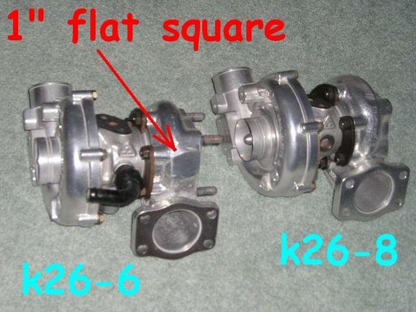
Comparing that to the previous picture it looks like the flat spot is on that K26/6. I've checked my K26/8 and it has the correct ...03 ending part number on the blue plate as well as no flat spot.
Comparing that to the previous picture it looks like the flat spot is on that K26/6. I've checked my K26/8 and it has the correct ...03 ending part number on the blue plate as well as no flat spot.
 07-01-2006, 12:51 PM
#17
Originally Posted by JDeitz951
With all due respect; No, no, no. I just replaced my K26/6 with a K26/8 and sitting on the bench side by side, the no. 8 hotside is visibly larger. Too bad I didn't have the camera that day. The outside of turbine housing on a 6 is spprox 1.5" wide while the 8 is approx 1.75". I have micrometer eyes so you know I'm right (30 years in designing and building machines does that).
Okay, I didn't mic it.

The IMPORTANT difference is inside the housing.
07-01-2006, 01:07 PM
#18
Addict
Rennlist Member
Rennlist Member
I've found the same results as ST. I've got a KKK #6, KKK #8, #8 replica Stg 2, #8 replica Stg 3, #8 replica Stg 5, and #10 Stg 5. The O.D. and width of the turbine housings are the same - kkk vs kkk and replica vs replica. It's the shape and depth of the cut inside the castings that differ.

07-01-2006, 01:36 PM
#19
Addict
Rennlist Member
Rennlist Member
For those also interested in a dimensional comparison see my post #4 here .
Having had both in the same car, I have to say that the K26-8 feels like a more �natural� match. It does come on at a higher rpm (about 3200 vs. 2800 rpm), but does it more gradually. It also holds the boost easier to red-line. The K26-6 can hold good boost to red-line too, but since its back pressure is seriously pushing on the WG valve, some clever WG control is needed.
Btw, a -6 turbine cannot be machined to a -8 turbine. The widths of the scrolls are different.
Laust
07-01-2006, 01:55 PM
#20
Addict
Rennlist Member
Rennlist Member
Originally Posted by Laust Pedersen
The K26-6 can hold good boost to red-line too, but since its back pressure is seriously pushing on the WG valve, some clever WG control is needed.
Laust
Laust
07-01-2006, 02:09 PM
#21
Burning Brakes
Thread Starter
Join Date: Oct 2002
Location: BALTIMORE MD
Posts: 855
Likes: 0
Received 0 Likes
on
0 Posts
Scott, on my last 951 (yours now) I took the lsd for granted on the track, I did not realize how good it was, it sounds like the s2 unit is better with the gearing as well. Maybe I should just put in the s2 lsd tranny and call it a day. I just got my 275 width r compounds for my rear 10" fikse wheels, I hope the rubber tames the wheelspin somewhat. If I increase the HP I will just increase wheelspin. What good is HP without traction!!!
Ben
Ben
07-01-2006, 03:10 PM
#22
Addict
Rennlist Member
Rennlist Member
Originally Posted by eclou
Laust, could you expound on this statement? I would be very interested in what this clever WG control consists of
Utilize the backpressure to counteract its push on the WG valve, by using the gas seepage between the valve stem and guide to the chamber below the diaphragm above the main housing. The chamber below the diaphragm is vented with 4 small holes, but some gas also escapes at the mating surface.
To make the boost pressure (close to) constant, seal the mating face, tap the four holes and plug them with screws. Drill a hole in one of the screws and adjust the hole-size to balance the resulting forces on the diaphragm and the valve head. Too small a hole and you�ll have increasing boost pressure and too large a hole and you�ll have decreasing boost pressure.
To make higher boost pressure possible I also added an extra spring.
In short: the gas force equalization tilts the boost curve (counterclockwise) and the extra spring translates it (upward).
It has actually worked for me for a year now.
Laust
07-01-2006, 09:54 PM
#23
Originally Posted by JDeitz951
With all due respect; No, no, no. I just replaced my K26/6 with a K26/8 and sitting on the bench side by side, the no. 8 hotside is visibly larger. Too bad I didn't have the camera that day. The outside of turbine housing on a 6 is spprox 1.5" wide while the 8 is approx 1.75". I have micrometer eyes so you know I'm right (30 years in designing and building machines does that).
07-02-2006, 04:17 AM
#28
Drifting
Join Date: Oct 2005
Location: Connecticut
Posts: 2,886
Likes: 0
Received 0 Likes
on
0 Posts
Originally Posted by Rich Sandor
No, in 1988 there was both an regular 951 and a 951S.
After reading a bit more in "Clarks-Garage" I came to the same conclusion!
07-02-2006, 09:27 AM
#29
Addict
Rennlist
Lifetime Member
Rennlist
Lifetime Member
Join Date: May 2001
Location: New Jersey Shore
Posts: 901
Likes: 0
Received 0 Likes
on
0 Posts
Originally Posted by LFA951
Actually, one inch equals 2.54 cm, so the 6 is 2.36" and the 8 is 3.14"
07-02-2006, 09:29 AM
#30
Addict
Rennlist Member
Rennlist Member
Originally Posted by Laust Pedersen
OK then, my trick WG. Since I don�t plan to sell modified WG�s (except if someone really wants it) then here is the basic idea:
Utilize the backpressure to counteract its push on the WG valve, by using the gas seepage between the valve stem and guide to the chamber below the diaphragm above the main housing. The chamber below the diaphragm is vented with 4 small holes, but some gas also escapes at the mating surface.
To make the boost pressure (close to) constant, seal the mating face, tap the four holes and plug them with screws. Drill a hole in one of the screws and adjust the hole-size to balance the resulting forces on the diaphragm and the valve head. Too small a hole and you�ll have increasing boost pressure and too large a hole and you�ll have decreasing boost pressure.
To make higher boost pressure possible I also added an extra spring.
In short: the gas force equalization tilts the boost curve (counterclockwise) and the extra spring translates it (upward).
It has actually worked for me for a year now.
Laust
This is on a stock WG? Do you have any pics or diagrams? I'd love to try the same on my Tial