
Recent Zeitronix install pics.
 06-13-2006, 02:50 PM
#1
Pro
Thread Starter
Join Date: Jun 2005
Location: Napa Valley, CA
Posts: 589
Likes: 0
Received 0 Likes
on
0 Posts
I want to share some pictures of my recent Zeitronix Wideband O2 install and contribute back to Rennlist, I’m very grateful for all the rennlisters who have shared their installations tips, searching the rennlist archives has made my installation a fun and successful one. Thanks, Marlon
I bought the Zeitronix wideband kit with boost sensor, but WITHOUT a display, since I would rather review the data sitting at my desk sipping on a cup of coffee (or having a beer) than while zooming around at 6,000 RPM .

Thanks to rennlist, it was easy finding a home for the new wideband O2 sensor

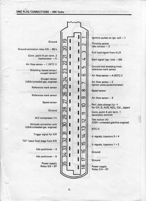
The hardest electrical part for me was finding that darn #21 DME tachometer wire. Well on my 86 951, it turned out to be the 1.5mm green w/ black stripe wire.
Also another tricky part was figuring out how to splice the boost sensor and the aftermarket boost gauge lines into the KLR vacuum/pressure line.
The solution turned up after a few trips to the local OSH hardware store, great tech assistance there. I picked up a couple of 1/8” National Pipe Thread (NPT) brass Tee’s , these are the smallest Tee’s that OSH carries, and also got some brass compression fittings for connecting these plastic lines.
3/16” Compression fittings for the top and bottom KLR lines into the brass Tee’s and a 1/8” compression fitting for my boost gauge line. The great thing about compression fittings is that one can assemble and disassemble as many times as desired and they provide a gas tight seal every time. So next time I need to get in there, I can quickly disconnect and reconnect these lines.


So now I’m enjoying the data logging feature and am able to log: TPS, BOOST, RPM, and AFR. I think this is the minimum monitoring data I can get away with to get a decent picture of what’s going on under the hood.
Z-log

I bought the Zeitronix wideband kit with boost sensor, but WITHOUT a display, since I would rather review the data sitting at my desk sipping on a cup of coffee (or having a beer) than while zooming around at 6,000 RPM .
Thanks to rennlist, it was easy finding a home for the new wideband O2 sensor
The hardest electrical part for me was finding that darn #21 DME tachometer wire. Well on my 86 951, it turned out to be the 1.5mm green w/ black stripe wire.
Also another tricky part was figuring out how to splice the boost sensor and the aftermarket boost gauge lines into the KLR vacuum/pressure line.
The solution turned up after a few trips to the local OSH hardware store, great tech assistance there. I picked up a couple of 1/8” National Pipe Thread (NPT) brass Tee’s , these are the smallest Tee’s that OSH carries, and also got some brass compression fittings for connecting these plastic lines.
3/16” Compression fittings for the top and bottom KLR lines into the brass Tee’s and a 1/8” compression fitting for my boost gauge line. The great thing about compression fittings is that one can assemble and disassemble as many times as desired and they provide a gas tight seal every time. So next time I need to get in there, I can quickly disconnect and reconnect these lines.
So now I’m enjoying the data logging feature and am able to log: TPS, BOOST, RPM, and AFR. I think this is the minimum monitoring data I can get away with to get a decent picture of what’s going on under the hood.
Z-log
Last edited by Trucho-951; 06-13-2006 at 03:16 PM.
 06-13-2006, 10:42 PM
#5
Rennlist Member
Join Date: Oct 2002
Location: Melbourne, Australia
Posts: 1,110
Likes: 0
Received 0 Likes
on
0 Posts
do you know the voltage curve on that map sensor, i wouldn't mind getting one for my tech edge.
edit, from zeitronix:
0.5V 0PSI absolute
4.5V 50PSI absolute
linear
edit, from zeitronix:
0.5V 0PSI absolute
4.5V 50PSI absolute
linear
Last edited by hally; 06-13-2006 at 11:05 PM.

Trending Topics
09-09-2006, 08:47 PM
#8
Trucho,
I know it has been a while at this point, but I have a question regarding your installation of the Zeitronix WBO2 data logger. When you spliced into pin 21 of the DME for the tach signal, did you have two wires coming from that port? One green and the other green and black?
I noticed that someone had been in to the wiring harness before, they had cut the solid green wire and put in a "two layer" wire, with only the inner wire being used. It is odd, I know. I am hoping someone can identify with me. I do not know what the green and black one is for.
I just completed the install and cannot get my car to start and I have the feeling that pin 22 is the problem.
09-09-2006, 09:33 PM
#9
Pro
Thread Starter
Join Date: Jun 2005
Location: Napa Valley, CA
Posts: 589
Likes: 0
Received 0 Likes
on
0 Posts
Originally Posted by chapstic951
Trucho,
I know it has been a while at this point, but I have a question regarding your installation of the Zeitronix WBO2 data logger. When you spliced into pin 21 of the DME for the tach signal, did you have two wires coming from that port? One green and the other green and black?
I noticed that someone had been in to the wiring harness before, they had cut the solid green wire and put in a "two layer" wire, with only the inner wire being used. It is odd, I know. I am hoping someone can identify with me. I do not know what the green and black one is for.
I just completed the install and cannot get my car to start and I have the feeling that pin 22 is the problem.
I know it has been a while at this point, but I have a question regarding your installation of the Zeitronix WBO2 data logger. When you spliced into pin 21 of the DME for the tach signal, did you have two wires coming from that port? One green and the other green and black?
I noticed that someone had been in to the wiring harness before, they had cut the solid green wire and put in a "two layer" wire, with only the inner wire being used. It is odd, I know. I am hoping someone can identify with me. I do not know what the green and black one is for.
I just completed the install and cannot get my car to start and I have the feeling that pin 22 is the problem.
If you are careful, you can unscrew the plastic cap off of the entire DME harness connector, there is a screw at the very end, and then crack it wide open so that you have access to the backside of all the terminal connectors. Then with on Ohm meter, you can probe and run continuity tests to pin point whatever wire you are interested in. hope this helps.
09-09-2006, 10:01 PM
#10
Damn, I was afraid you were going to say that regarding the wire color. I cut into the solid green (shielded) wire. I cannot find the thread, but there was a link to someone who installed the same system and said, "use the green wire from pin 21." I didn't notice that there were two coming out of the same pin at the time of my handy work.
Guess which wire I am splicing into tomorrow? Did I do irreparable damage to the shielded wire since I have to undo my work from today? It was cut inside the firewall, in the passanger compartment.
Guess which wire I am splicing into tomorrow? Did I do irreparable damage to the shielded wire since I have to undo my work from today? It was cut inside the firewall, in the passanger compartment.
09-09-2006, 10:08 PM
#11
Addict
Rennlist Member
Rennlist Member
Solid green isnt the speed and reference sensors. Theres a few wires that are solid green, and layered but not in the shielded sense. The VR sensors go to multiple pins on the connector anyway so if you hacked into only one wire coming from the connector then that isnt it.
Are you ABSOLUTLY sure that you had the correct pin?
Are you ABSOLUTLY sure that you had the correct pin?
09-09-2006, 10:48 PM
#12
Originally Posted by theedge
Are you ABSOLUTLY sure that you had the correct pin?
As I mentioned, I didn't notice that there were two wires coming out of the same pin, pin #21 on the DME (for the record, the DME is the larger of the two computers in a 951 from 1986 yes?). I didn't look at the other pins but, off hand I don't recall seeing any other wires sharing a pin out.
though, theedge, I did notice there were a few green wires and I quad check my work, and three more times after the car wouldn't start. I was a timid as could be, cutting into the artery of my car, for this exact reason.
I will take a pict in the AM for clarification (and to put my mind at ease.).
09-09-2006, 11:20 PM
#13
Addict
Rennlist Member
Rennlist Member
Originally Posted by chapstic951
Yep...(real quick, what is a VR sensor?)
As I mentioned, I didn't notice that there were two wires coming out of the same pin, pin #21 on the DME (for the record, the DME is the larger of the two computers in a 951 from 1986 yes?). I didn't look at the other pins but, off hand I don't recall seeing any other wires sharing a pin out.
though, theedge, I did notice there were a few green wires and I quad check my work, and three more times after the car wouldn't start. I was a timid as could be, cutting into the artery of my car, for this exact reason.
I will take a pict in the AM for clarification (and to put my mind at ease.).
If you take some pics ill have a look at them and see if I can spot anything.
09-10-2006, 12:16 PM
#14
My camera is terrible for close up shots, but you can see that there are two green wires going into pin 21 (checked it another 3 times). The skinny green on is actually green and black (on the left) while the thicker solid green is on the right is layered. Should I be using the grn/blk for the tach signal?
09-10-2006, 01:12 PM
#15
Addict
Rennlist Member
Rennlist Member
Ok from the 86 Turbo wiring diagrams, there should be two wires coming from there. You do want to use the smaller Green/Black one, its the wire that goes to the tach in the gauge cluster.
That big solid green layered one would in theory work as well, but it goes to the KLR. To get a signal from it for RPM youd have to cut into the very inner wire but I wouldnt do that.
Check that maybe it hasnt pulled loose at the other end, pins 9 and 10 on the KLR (smaller box). Is there still a connection from the outter part of the big green wire to pin 21?