When you click on links to various merchants on this site and make a purchase, this can result in this site earning a commission. Affiliate programs and affiliations include, but are not limited to, the eBay Partner Network.
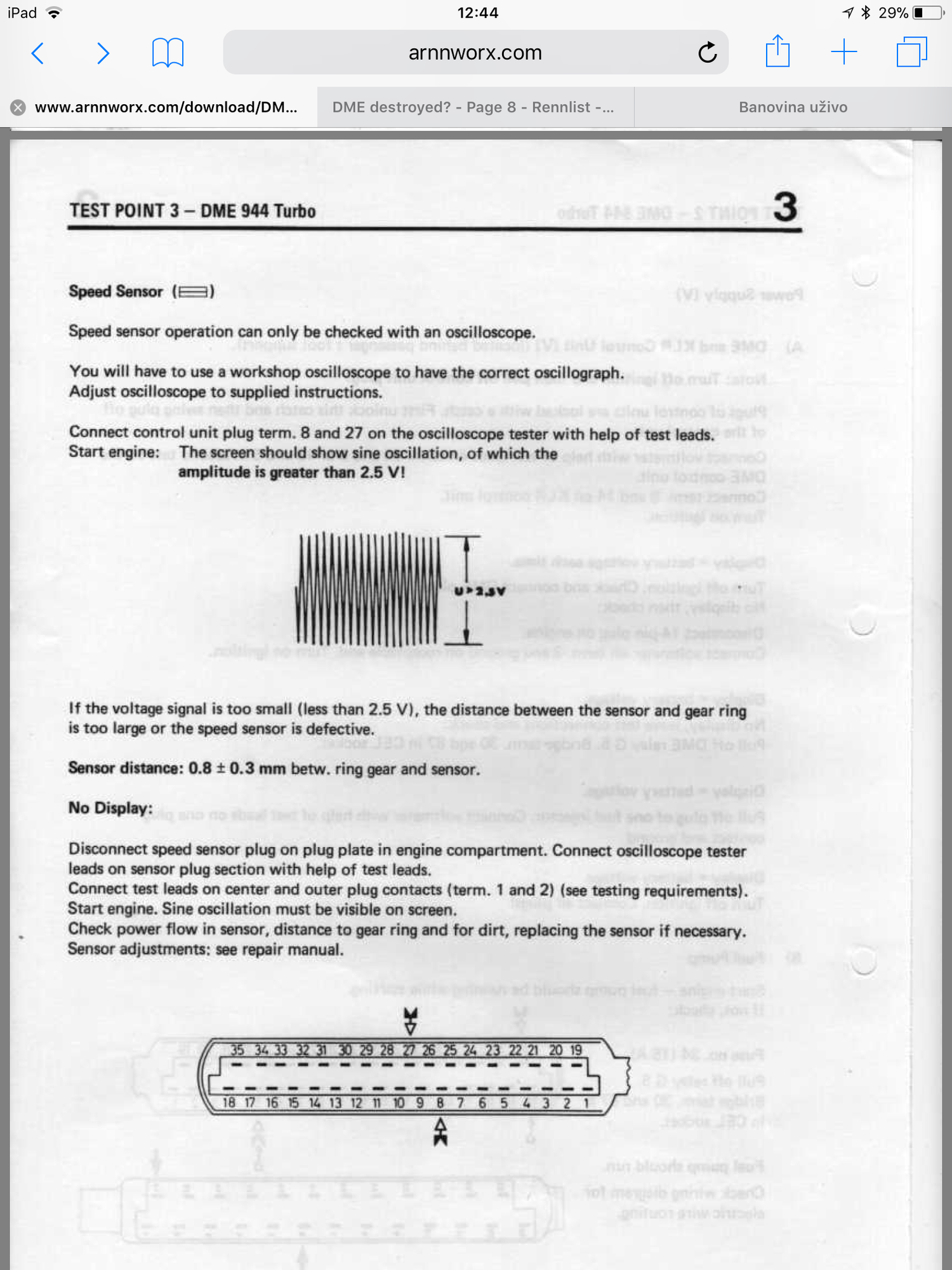
The DME/KLR test plan notes appear to confirm what I'm seeing is good; that is, the ref sensor needs to be 2v above the centre line only, where the speed drawing suggests the entire wave is important:
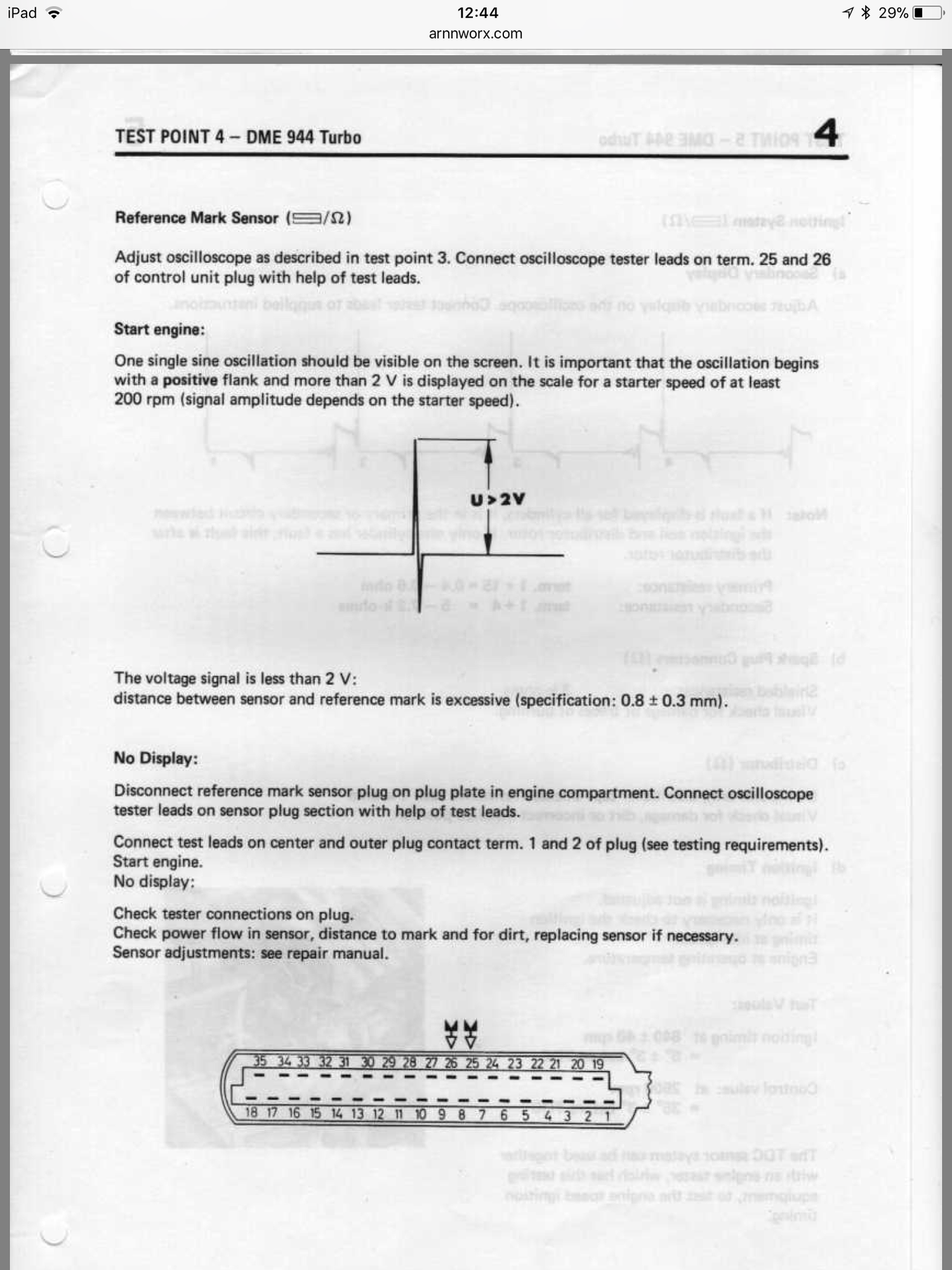
While I climb underneath looking for mistakes, can someone explain how to check the following scope test from the Test Plan; it doesn't say where to hook up the probes to get those results... thanks
Ok, quick look underneath and I can't find anything out of place. Will look more another time; have to pack it in for today.
Did some more scoping. Lord help me.
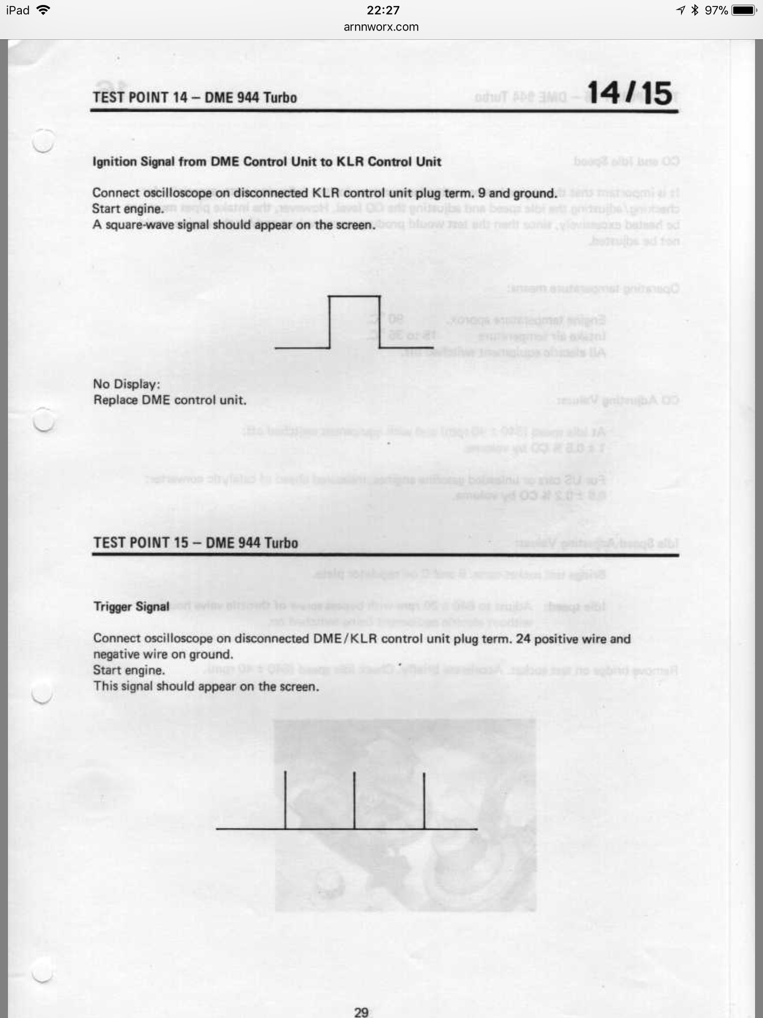
Test Point #14 & 15 appear to be the final official test of DME unit by checking if it's feeding the KLR at the KLR's harness. If anyone (Tom?) could peek at the following readings from KLR pin 9 to ground & 24 to ground (as per Test Plan Point #14 & #15) to see if anything can be read, would be much appreciated.
I didn't know what /div's to set for time and volts to pick up these signals; KLR pin 9 is ignition input from DME; KLR pin 24 is "tr - signal (input)". Tom, you mentioned Pin 9 is a low-level logic signal, but I don't know how many volts is low-level.
I tried a whole bunch of settings and here are brief samples using 1ms .5v; .5s .5v; and both repeated with 50mv/div.
To my eye, none seem to show what they are supposed to; but, as usual, I could be wrong
Pin 9 at .5v shows something, but I don't think it's the "square wave" it should be (see post #1 in this thread).. at 50mv, nothing shows.
Pin 24 is the opposite: it shows something at 50mv but barely any movement at .5v. It, too, doesn't appear to be the proper "comb" pattern for this pin signal.
Of course, maybe I should be using different time/div and v/div settings.
Last edited by Dan Martinic; 03-31-2018 at 04:00 PM.
Reason: Corrected spelling
The S100 output going to the 8051 interrupt pins are easier to watch on the scope (simple 0 or 5v square pulse trains)
My next opportunity for diagnosis will be Monday morning. I would like to try this; thank you for the specific voltage, though I'm not sure how to measure "0" volts? But if it's 5volts, I'll set the scope at 5v/div (I think that's the max on my scope) [EDIT: and with a high trigger like 4volts)
What sweep speed (time/div horizontal)?
And.. when I open the DME, I'm assuming the pins are labelled? I have to find which pins you referred to again.
It's hard to know if your scope results are a function of bad signals or not having the scope set up to capture the signals correctly, or maybe both. As a point of reference, attached is a screen shot of my (cheap) scope comparing DME pin 21 (same as KLR 9) and pin 32 (same as KLR 24). See settings there too. If you have an ignition pulse, and if the scope is set up right and working, you should see something like that. Either way, your screen shot of the ref sensor signal wouldn't give me comfort if it's not showing some sine wave shape, and your videos of KLR 9 and 24 are hard to interpret -- could be just noise or too far out of range. Re test point 5, I'd check the coil resistance against those specs. Pins 15 and 1 are the small black and green wires, and 4 is the big lead in the middle going to the distributor (no idea why they are numbered that way). You should get half an ohm or so between the two outer (black and green) pins, and 5 to 7.2k ohms between pin 1 (green I believe) and 4 (center coil lead). I wouldn't mess with the scope on the coil -- too easy to fry something. I worry about you checking the S100 output -- nothing is marked and you need to probe the specific pins on the microprocessor. If we knew you did have speed/ref signals, and knew you didn't have ignition on DME 21, then I'd check if the pulse is dropping between the S100 and 8051, or inside the 8051, but that's for pinpointing the source once you know your pulse is dropping out somewhere. Scoping DME 21 is virtually the same in terms of hooking up the scope and seeing the pulse, so no benefit right in probing into the DME I'd say.
I'd be curious what the signals looked like if you swapped sensors in the holes. If the issue follows the sensor, then maybe one is bad. If the problem stays on the ref sensor side, then the sensors are probably good and the problem elsewhere.
I too was thinking of switching sensors, and now I'l do that first, then run the same scope settings—at least my sensor scoping is getting better.
No probing inside DME.. got it.
I see the settings for pin 21 are 5ms 5v. Very helpful! FYI your equivilant to klr pin 9 is upside down square and the other pin is supposed to be straight lines above centre, not square wave; but maybe that's a function of the scope setting (sweep speed).
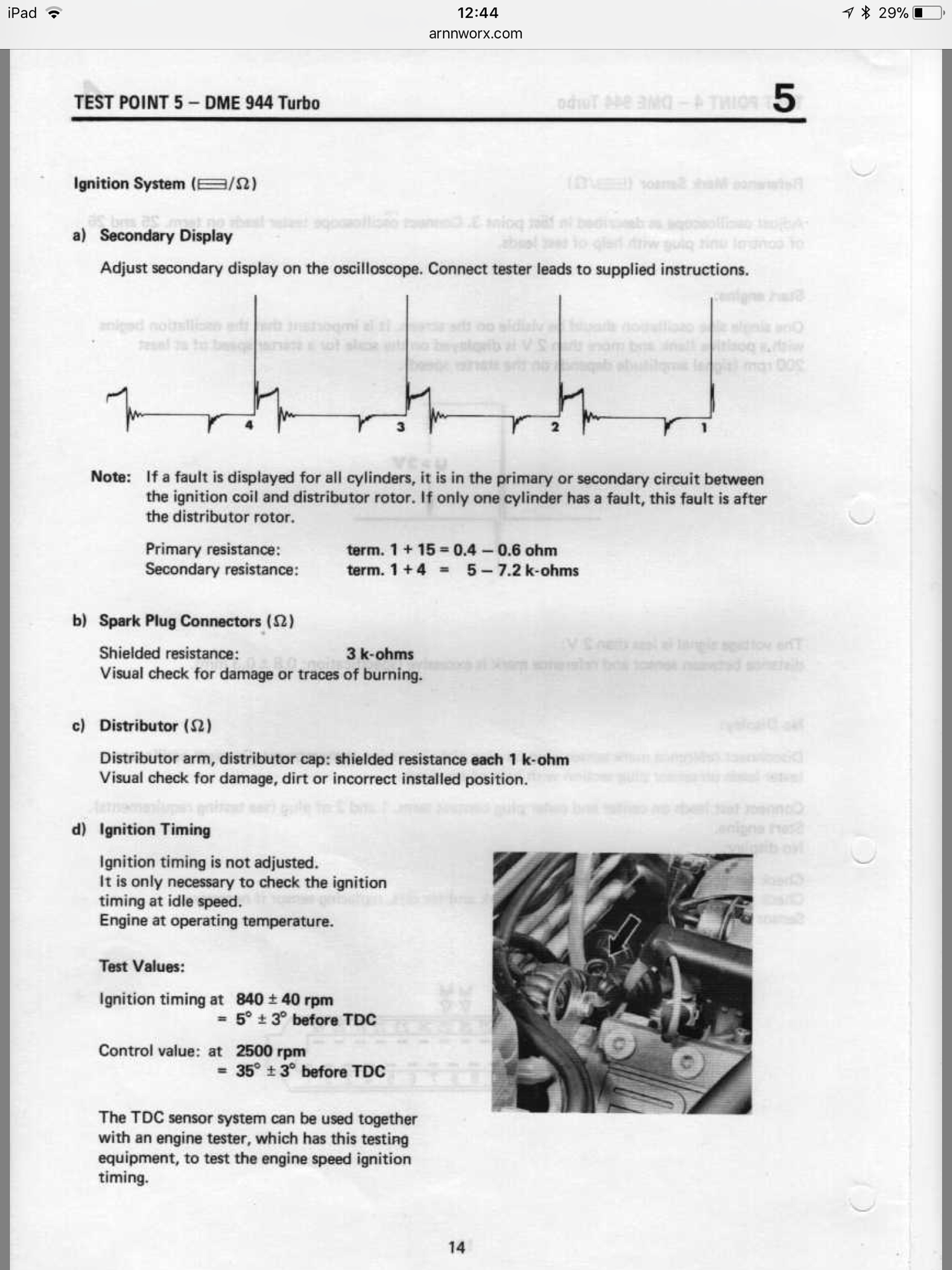
I did do a basic coil ohms test few days ago and didn't read right between green & black; the suggestion was to remove the wires first. Funny the Test Plan just assumes you know this. I have been forgetting to do this. Perhaps I'll squeeze this in quickly during the day's obligations. Think anyone will notice I've dissapeared to the shed for a while? lol
I wouldn't read too much into those factory wave forms. The second one is odd and probably just a square pulse compressed too much. You are looking for square (i.e., on/off) voltages between high and low. I was capturing the latency (timing impact) of the post-KLR pulse so had it set up to show when the ignition pulse rose...but IIRC I set my up with the polarity correct so that's how it will look in real life...
For all those observing today... Happy Easter! In between events, I snuck out for more diagnosis....
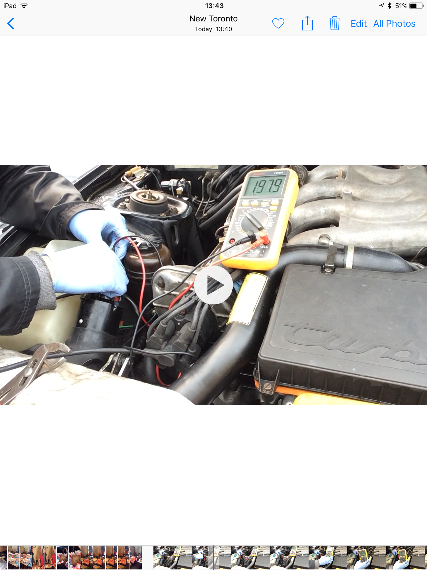
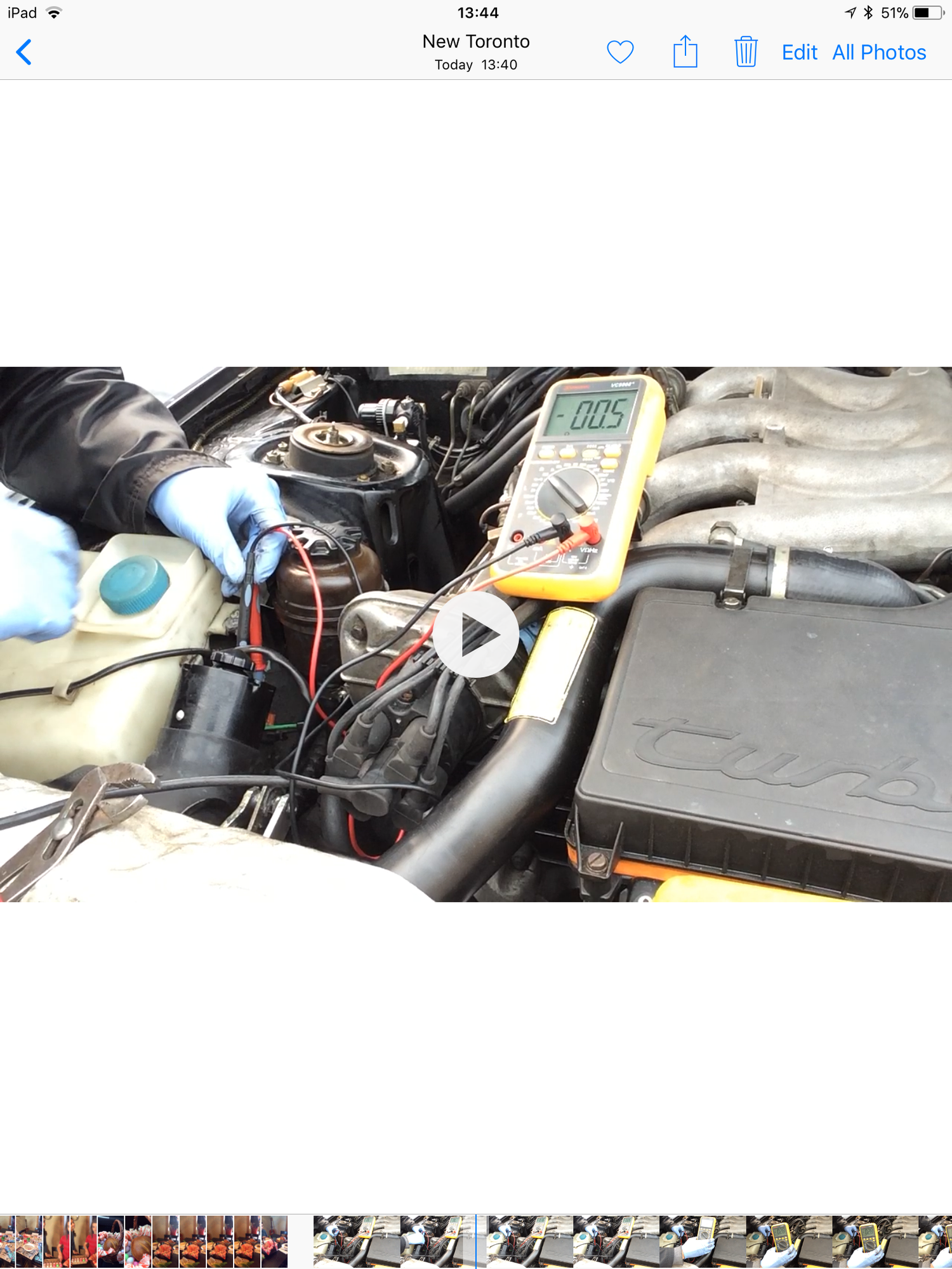
I did this test before, but it was suggested that it needs to be done with coil wires unplugged. Now, I've done it again with no wires attached to the coil. Funny, same results.
Are they correct? To my eye, the primary doesn't match the spec; there's a negative (?) in front of the final resting value.
Not sure what to tell you there about the primary coil. You put the test leads on the two small screws with nothing else connected to them? Negative resistance is a thing, but is above my paid grade and suggests power is leaking into the circuit (presumably from the secondary coil, would be my guess). I thought maybe that happens on a recently fired coil, but I just went out and tested two different coils and the primary coil resistance was around half an ohm as expected, even if I measured immediately after firing the coil. Might be worth trying a spare coil.
EDIT: you set the multimeter up for the correct (very small) ohm range, right?
Absolutely nothing connected to the coil. (EDIT: though it looks like the green wire is still connected, it's not; the wires are just sitting next to the coil, keeping their same shape). Same results I got days ago with the wires hooked up.
Yes, the multimeter for the primary test is at the lowest ohm setting which is 200 ohms; the next up is 2k, then 20k, ...
So, the primary's not right, is it? I should probably order a coil. $125 up here!
I managed to replicate your scope test today, same settings as you use in your screenshot. I'm probing KLR pin 9; I'm not sure how you probe DME pins 21 & 32 (BTW: pin 21 is for "Tachometer-1", is that what you meant? Or did you mean DME pin 31 which is "trigger for KLR"? And, the DME connector is sealed in back so you can't get at the pins while it's connected?!?)
One strange note: I did it twice, once with the trigger ON (set at 0v) and again trigger OFF. Trigger ON results in absolutely nothing. However, during the trigger OFF test, just when I turn the ignition key, but before cranking, the trace jumps way up! To stop this, I set channel coupling to AC and it doesn't happen. However, still no signal while cranking.
From Clark's garage, I'd like to try this coil test, but I want to make sure I don't blow anything up.
I have a couple of question about the procedure as described (see below). Specifically, Step 3: where do you connect the other end? I've been grounding spark plugs simply laying them down on some metal like the intake manifold; Step 7: Are the black & green (esp green) wires connected to the coil during this test? EDIT: I realized that, obviously, the black has to be connected; question is could leaving the green connected damage the DME?
"Ignition Coil Test
Disconnect the ignition coil output wire at the distributor cap.
Connect a spark plug to the end of the ignition coil output wire which you just disconnected.
Connect a ground wire to the threaded portion of the spark plug.
Disconnect the ignition coil ground wire from the negative terminal on the coil (Green Wire).
Connect one end of a ground wire to the ignition coil negative terminal.
Turn the ignition switch to the ON position.
Tap the other end of the ignition coil ground wire jumper on an good grounding point (for example the battery negative terminal) and look for sparks at the spark plug that correspond to the frequency of your tapping of the ground wire.
If you have a good spark at the spark plug, the ignition coil is good.
If you don't get a good spark, check for approximately 12 VDC from the coil positive terminal (black wire) to ground with the ignition switch in the ON position. You should also get approximately 12 VDC from the coil negative terminal (Green wire) to ground
Last edited by Dan Martinic; 04-02-2018 at 07:43 AM.
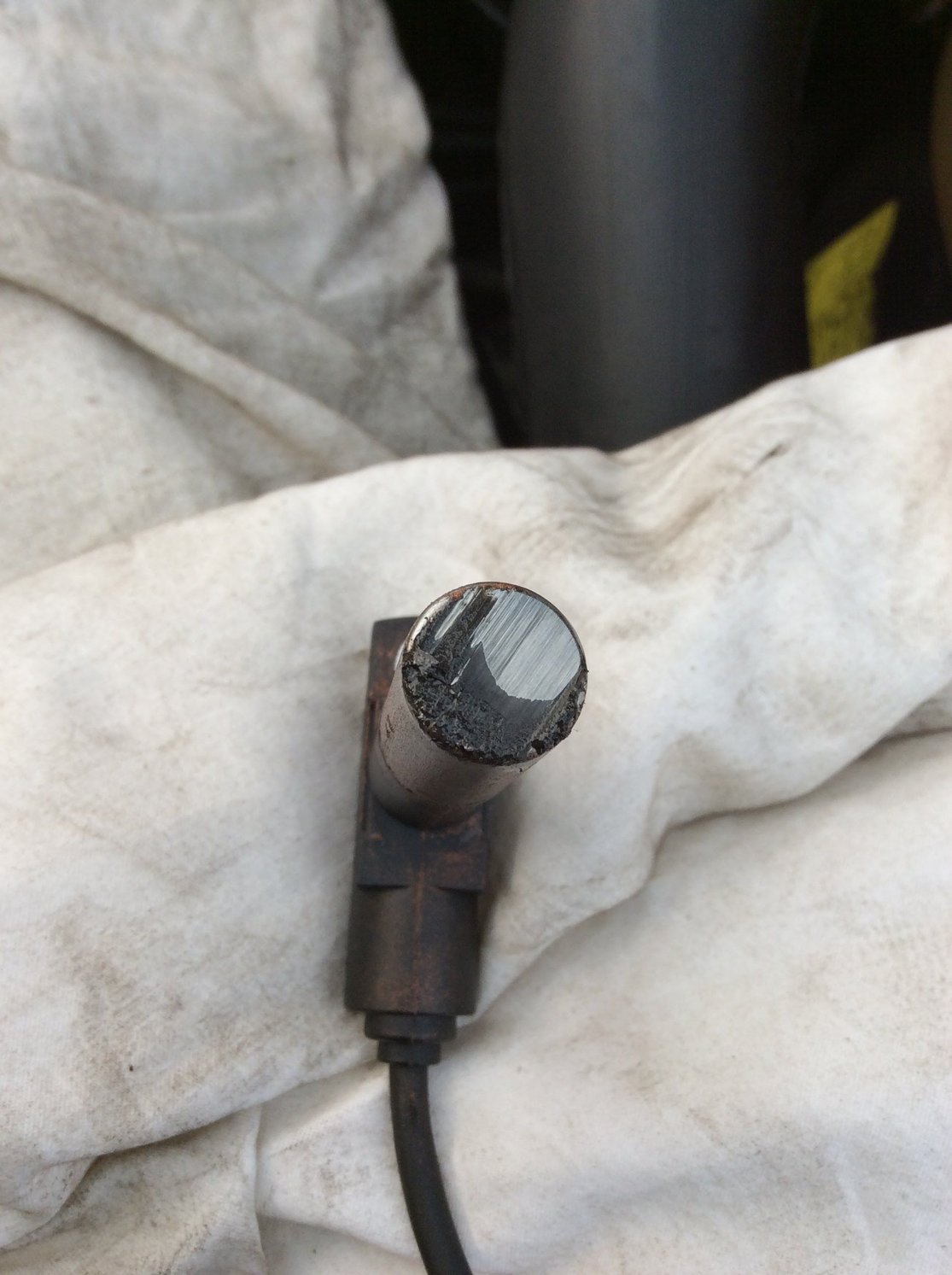
I decided to re-gap the sensors. When I took out the speed sensor, um, I was a little surprised to see this:
I pulled the reference sensor; as before, it looks fine.
This makes little sense, seeing as the Speed signal is showing very fine on the scope.
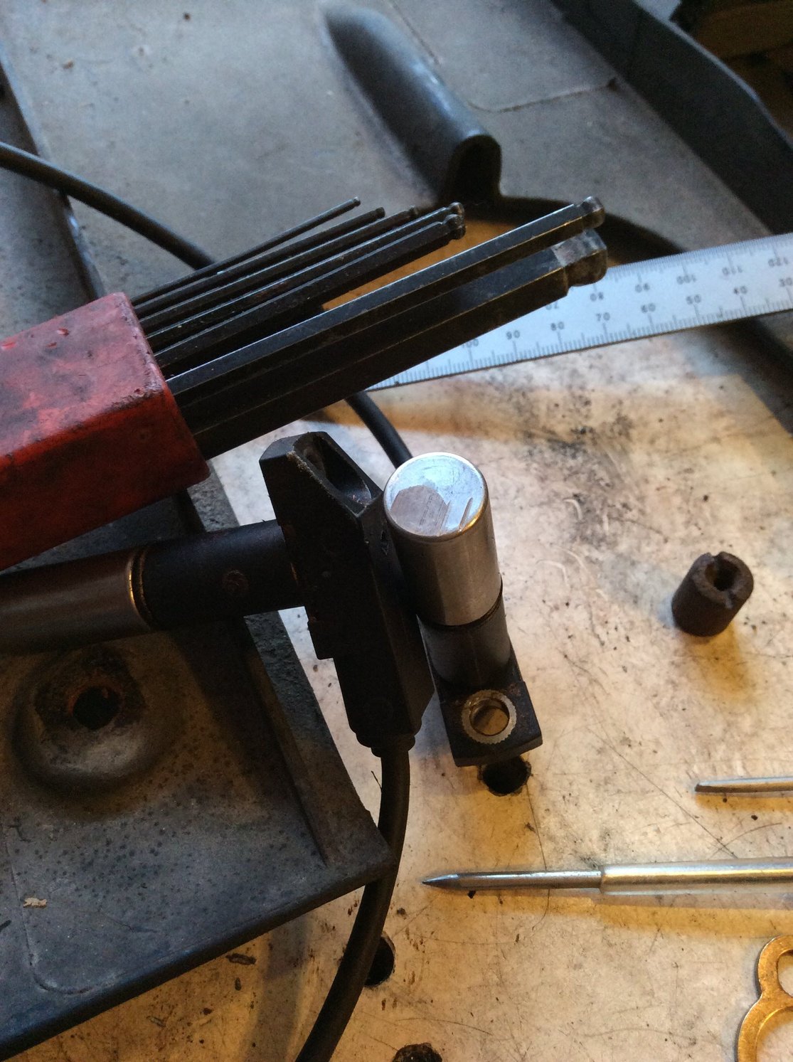
I guess my homemade tool, using the old sensor, is a little off. I did try to measure it and it looked same as the new one, but, at less than a millimetre, let's just say I don't have machinist-grade measuring tools.
I'm going to glue another washer on the like-new ref sensor and re-gap the bracket. I don't know what kind of glue to use, since I'll have to 'unglue' the washer after; I'll just use the same Krazy Glue but only a drop or two.
I will also try to put the speed sensor back as is. Cleaned, it looks like it might still work; only 1/2 the surface is scratched and the magnet is still strong. Might as well try.
Ok, so the sensors were too close. I hope this makes the difference........
From Clark's garage, I'd like to try this coil test, but I want to make sure I don't blow anything up.
I have a couple of question about the procedure as described (see below). Specifically, Step 3: where do you connect the other end? I've been grounding spark plugs simply laying them down on some metal like the intake manifold; Step 7: Are the black & green (esp green) wires connected to the coil during this test? EDIT: I realized that, obviously, the black has to be connected; question is could leaving the green connected damage the DME?
"Ignition Coil Test
Disconnect the ignition coil output wire at the distributor cap.
Connect a spark plug to the end of the ignition coil output wire which you just disconnected.
Connect a ground wire to the threaded portion of the spark plug.
Disconnect the ignition coil ground wire from the negative terminal on the coil (Green Wire).
Connect one end of a ground wire to the ignition coil negative terminal.
Turn the ignition switch to the ON position.
Tap the other end of the ignition coil ground wire jumper on an good grounding point (for example the battery negative terminal) and look for sparks at the spark plug that correspond to the frequency of your tapping of the ground wire.
If you have a good spark at the spark plug, the ignition coil is good.
If you don't get a good spark, check for approximately 12 VDC from the coil positive terminal (black wire) to ground with the ignition switch in the ON position. You should also get approximately 12 VDC from the coil negative terminal (Green wire) to ground
That test description is a bit confusing and relies on having good power to the coil on the black wire. In step 3, the point is just to ground the plug. If the threads make solid contact with the intake, that should be good enough. You absolutely must remove the green wire in step 4! Otherwise, you will be making a direct short in the DME. Step 5 says to connect a "ground wire" to the negative side of the coil, which is confusing. That wire should be just a free wire -- one side gets connected to the negative post of the coil and you tap the other side to ground to check for spark.


 03-31-2018 | 01:48 PM