When you click on links to various merchants on this site and make a purchase, this can result in this site earning a commission. Affiliate programs and affiliations include, but are not limited to, the eBay Partner Network.
As for the sensors being bad, that would be a good one: since I reversed them and got the same readings, they would BOTH have to be bad.. and whichever is installed in the speed hole appears to have an excellent signal on the scope (see post 137). However, if that ends up being the case, I'm going to totally lose it!
At least I can now replace & gap sensors quicker than it takes to make a peanut butter sandwich. Crunchy.
My hunch has been on the harness for a while now, and even if something else is causing your issue, I think the money was well spent on a replacement harness.
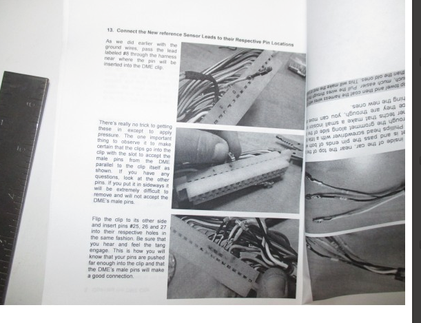
Until it arrives, I have to ask: how do you install this thing?
The place I ordered from -- chosen because they offer USPS which saves us Canucks big customs "processing" fees, aprox. 45US+ per item -- has these images that suggest you install the other end into the DME harness. But, my harness looks to be a solid piece of plastic?
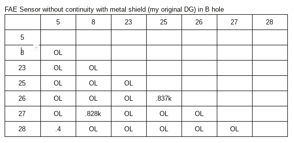
I sent you a PM. If you replaced your original Bosch speed and reference sensors with FAE brand sensors, you must test them to see if the center pin on the harness connector has continuity with the metal shield end. If there is continuity then the sensors will pass all the tests but will send a false ground signal to the DME, preventing the car from running. This is what happened to my car.
After I cut off the metal shield the car started instantly.
Ideally, you should replace the FAE sensors with oem Bosch.
I am ordering the reference sensor harness; unfortunately, Lindsay doesn't do USPS international, so I'm getting it elsewhere that does, but it appears to be the same one.
Now.. following my new lead (thanks Perry) & outside to test some FAE sensors and DME ohm values....
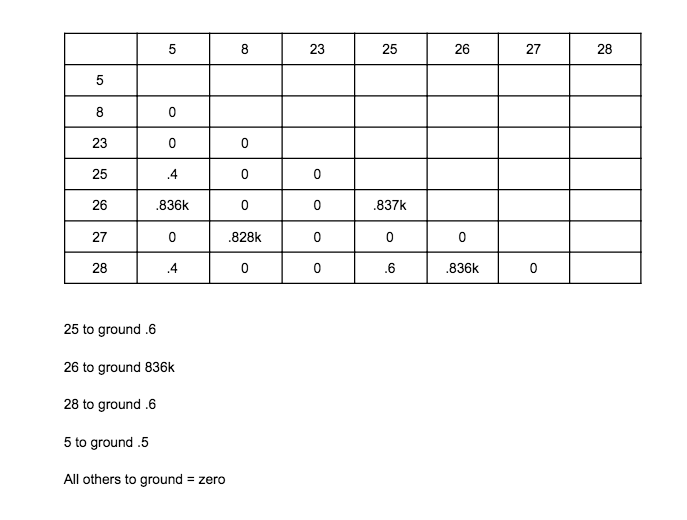
EDIT: My "0s" in the chart are actually "OL" or infinity on the meter
EDIT: By "to ground" above I mean to the chassis (I used the door arm thing as a ground)
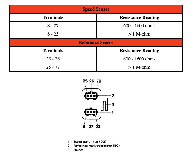
I then pulled the reference sensor and I have continuity between pin 1 on the sensor (furthest on one side, labelled "1" inside the connector) and the metal shield; the centre and the other pin (pins 2 & 3 inside the connector) have no continuity with the shield:
I got up at 4am this morning to complete the tests from last night. Very interesting findings!
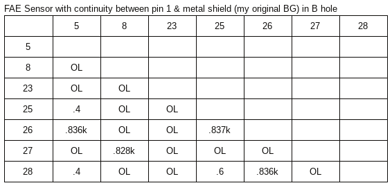
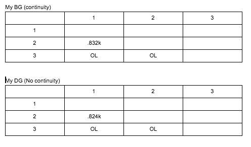
ONE of my FAE sensors (my original BG) has continuity between its pin 1 & the metal shield; the other (my original DG) DOES NOT.
Updated chart -- confirmed and clarified the original chart and tested with sensors switched places
The sensors by themselves, removed from the car:
NOTE: each time I tested at the DME pins (first two charts), I installed the sensors with their bolts fastened
I am going to call the supplier and add 2 new Bosch sensors to the order (after putting the order for the harness yesterday, I called them and asked them to hold the shipping until I confirm wether or not I'd like new sensors)
Wish me luck that this is the actual issue... one FAE sensor that has continuity between its outside "pin 1" (pin 25 or 8 in Clark's diagram above) and its metal shield/bottom casing
Last edited by Dan Martinic; 04-04-2018 at 11:07 AM.
Reason: Clarified titles of charts 1 & 2
I had forgotten the exact details of Perry's issue, but it's coming back to me after reading the recent updates. If you're inclined to do more testing while you wait for the parts, I think you should be able to verify it with the scope. If you remove the plastic cover on the DME plug (as shown in the Lindsey Racing instructions I linked to) and slide it up out of the way, then you can plug it in to the DME and probe the pins through the top at the same time. If the signal wire is indeed shorted to the shield, then you should get a good signal from the sensor when unplugged, but nothing when it's plugged into the DME (because the DME grounds the shield). Of course if you're buying new sensors anyway it might make sense to just wait for those.
What gets me is when I switch the sensors (ie. put the B into the D hole), I get "proper" resistance readings; but, when I switched these in my testing on the weekend, it made no difference to the no-start symptoms
Last edited by Dan Martinic; 04-04-2018 at 10:26 AM.
Reason: clarification
The reference sensor signal must be as shown on the Porsche diagram. The signal must go positive and then negative. A positive only signal will not work.
So you need to look at the sensor connector signal, using an oscope, then connect the sensor to the DME harness, and look at the DME connector signal. If there is a harness issue, you will see a difference between the sensor connector signal and the DME connector. Or if both are correct, check from the back of the connected DME connector.
It would take a diode theory course, EE degree, to explain why you need both plus and minus on the Ref signal, but the short answer is the DME pulse is generated when the plus portion of the signal goes negative.
You are very close to solving this.
The relevant diode theory here is that electronic technicians are taught in the steady state electricity world. Where a diode passes the signal only one direction. While true in steady state, not true in the millisecond world.
Turns out that when the PN junction is forward biased, current flow. And then quickly reversed biased, as in the REF signal spike going negative, the PN junction will allow a brief current flow, (mil or micro second, depending on PN junction construction) in the reverse direction. This action is the basis for all signal generators, as this small reverse bias current flow is amplified to be a pulse.
With the sensors removed from the car, none of the pins should have any continuity with the metal shield on the end of the sensor.
If you look at the wiring diagram, the wires from the connector to the sensor have a shield/sheath (a finely woven metal mesh tube running the length of the wire) that is between the exterior rubber insulation and the sensor wires. This mesh is grounded through pins 5 (for the reference sensor BG) and 23 (for the speed sensor DG) on the DME. The shield on the end of the sensor should not have continuity with anything when the sensor is out of the car.
The other two pins in each connector should have a resistance between them of 600 to 1600 Ohms when tested through the harness at their connections with the DME.
In your video, it shows that the metal shield on the end of the sensor has continuity with one of the pins. That should not happen.
I would replace both sensors with oem Bosch. I would not order a new harness. I ordered and installed one from Ian at 944 Online. The harness was high quality, but installing it into a 30+ year old car meant that you are very likely to break some of the brittle, fragile plastic pieces of the DME to harness connector. Also, it's a pain in the butt to work the wires through the firewall and into the rubber boot on the DME connector. Very fiddly.


 04-03-2018, 12:30 PM