When you click on links to various merchants on this site and make a purchase, this can result in this site earning a commission. Affiliate programs and affiliations include, but are not limited to, the eBay Partner Network.
I agree. I will do it... eventually. Looks like the intake comes off?
In the meantime.... the two core wires are intact, and I do not believe there is an issue there re: starting
Tom, I am trying to figure out what looks off in the ref signal. Looks like I incorrectly titled a couple of the clips; clearly, two of them are 5s/div not .5s.. and The .1v is actually 1v. [EDIT: Nope; they were all titled correctly. See follow-up post below]
See, I was doing a million tests with all kinds of settings... trying to get a nice solid waveform like in the book pictures. I do find the time/div confusing in that I get different V height at different speeds (?)
I could also be cranking a little slow, thus showing a bit less Volts... but I think it jumps pretty healthy in some of those clips.
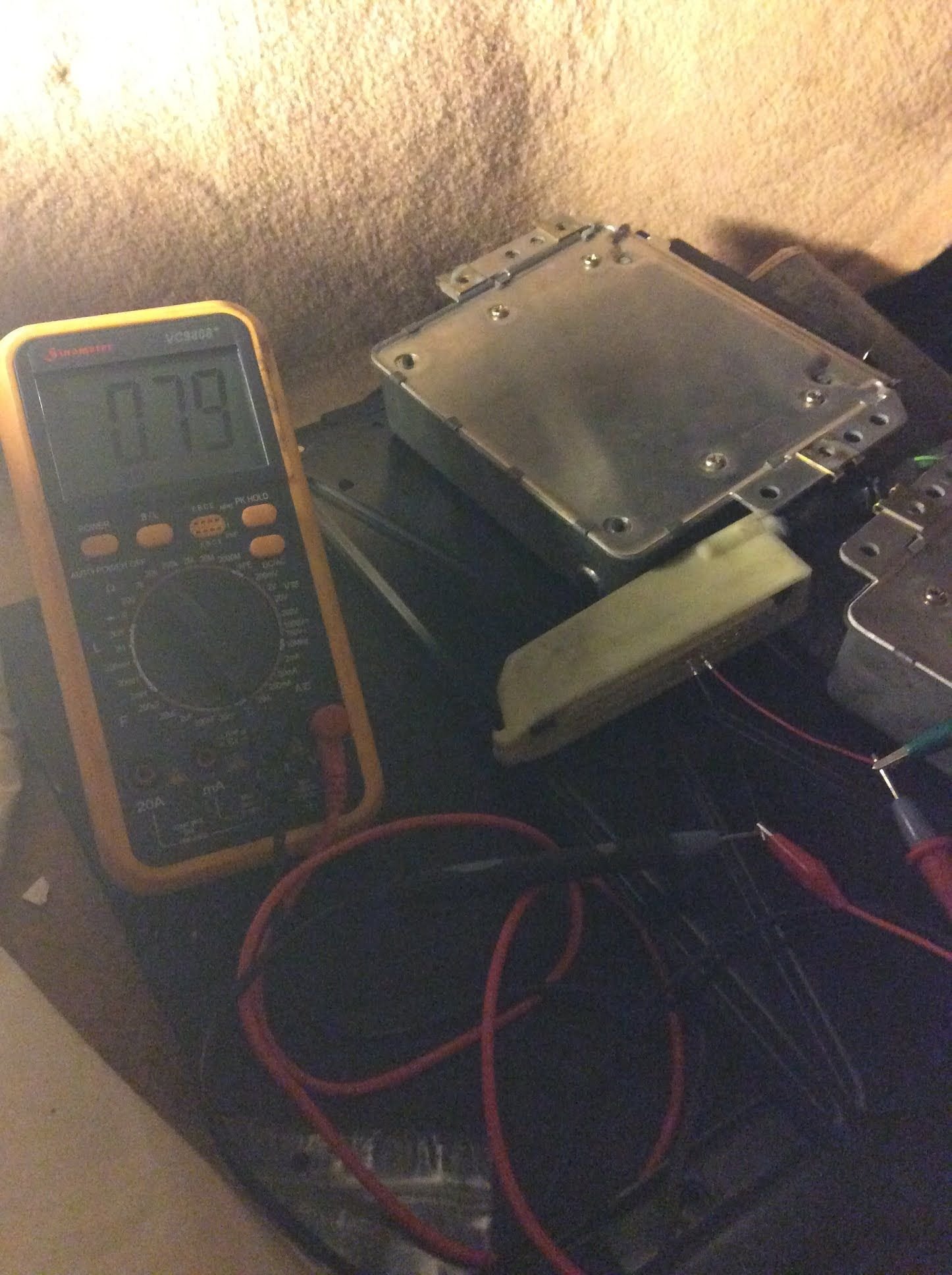
BTW the voltmeter shows exactly what the ECU Doctors video shows ffwd to about 2:50... ironically, they test my same year...
Try this, with the main DME connector disconnected, check for continuity between the two pins in the harness-side connectors. They should be separate with zero continuity (open, infinite resistance) so if you see any continuity between the two pins in the same connector, then there is a short inside the harness somewhere.
Ok, will check tomorrow, thanks! Packed it in for the evening. Kids wondering when they'll be eating ha ha
Ok, the low voltage on the multimeter must be how it averages out the voltage spikes, but multimeters all act differently with signals like that so it's really not the best test unless you know how your multimeter looks when the sensors work. The factory spec is a pulse of 2 volts or more (with the ac waive starting on the positive slope) cranking at least 200 rpm. In one of your videos marked .1v, it was jumping about 2 or 3 divisions, so if those were actually 1 volt divisions, then the signals looked good. The ref signal was still not the nice one pulse per rev you want to see, but that's likely due to you triggering and timing selections on the o-scope. Try 2ms with a positive trigger. If you are getting good speed and ref signals, then with that scope you can test the pulse train into and out of the S100, then to the 8051 interrupt pins, then out to the KLR, then back, and finally out to the coil, to see exactly where you are losing the ignition signal. Then you be "the guy" yourself.
The original videos clearly show the scope settings, so I spent a little time trying to see what exactly I titled what. Turns out, they are all titled correctly.
I've uploaded a couple more from the batch... this time in HD so the scope settings are now (kinda) visible. Correctly titled:
Now, I am not sure why the ".5s .1v" only jumps 2 .1v divisions, but the .5s 1v clearly jumps off the screen. However, the frequency of the jumping is much further apart.
On a scope, is the reference sensor supposed to jump steady like the speed sensor or further apart like my .5s 1v video?
And.. how does this person get such a nice slow-motion clear video..
his 10ms clip (first one) is so clear and reveals in a slow motion; I can't get anything like that on any setting. Is it because he's using a digital scope? The analogue one I have has a "Delay" function. Should I be using that?
I am also confused about "coupling": there is channel coupling ac vs dc as well as trigger coupling (many options including ac/dc, noise reduction, etc). I had it set on AC all around. What is "coupling"?
Last edited by Dan Martinic; 03-25-2018 at 08:22 AM.
Reason: Added missing video clip
Hard to say if your settings are off or if the ref sensor signal is bad. Check for continuity between the ref sensor connector pins on the harness side without DME connected. The scope in that slow-motion video is using a "trigger" so that the screen just shows when each pulse starts. That image you see is just the pulse happening over and over in the same place on the screen. Have you tried using the tiggers? He's using DC coupling, and probably has the scope leads reversed on pins 25 and 26, which is why it's (incorrectly) starting on the negative slope. Positive lead is 25, negative lead is 26. I don't think that flicker you are seeing in the first video is an actual sensor pulse, but rather some noise or artifact from the way the scope is set up. The timing isn't right for a real pulse (see below). Since you are getting a pulse on the speed sensor, if you want to learn that scope, try dialing it in until you can capture a nice sine wave on the screen, like the other video (or change the divisions a bit so you can see a longer segment of the wave form -- like an EKG heart monitor). Once you get the hang of that, go back to the ref sensor and see if you can dial it in. As for timing, the speed sensor sits over the flywheel starter teeth, so you will get 132 pulses per revolution. If you are cranking at (say) 200 rpm, that means you'll see 26,400 pulses a minute, or 440 pulses a second, or one pulse every 1/440 seconds, which is just about 2.27ms per tick. Since the starter teeth are a consistent saw tooth pattern, that means you'll see a continuous sine wave with a frequency of about 2.27ms peak-to-peak. If you go back and look at your first speed sensor video, where you have it set at .5ms and 1v, you'll see that it is about that -- maybe a little slower at 2.6ms or so (suggesting you are cranking a little under 200rpm) -- so that one looks good. You can apply the same logic to figure the ref sensor timing, but it only has 1 pulse per revolution, not a continuous sine wave like the flywheel teeth, so that's why setting up the trigger to catch and display it is important to make it look like the one in the other guy's video (if you happen to have a signal that is).
After a day out with family, what else is there to do but hook up a 'scope to 1980s sports car? Nothing, that's what
Alright, I figured out how to engage the trigger function. I set it to NML (normal). DC coupling. Only did three different time/div tests, all at 1v. What I get is really strange. The suggested 2ms (and 10ms as per guy's slow-motion video) result in.. well.. nonsense to me. Only when I slow down the time/div to the slowest setting, .5s, does the signal appear somewhat what I expect.
No hi-def upload option tonight (?) but the titles are accurate, I promise....
If the .5s is to be believed, the ref sensor is triggering off the chart--way more than 2volts
EDIT: If the above videos show something other than the oscilloscope with trigger, I can't explain why; for some reason, depending if I'm logged in or on a mobile device, some of the videos are actually older ones with the voltmeter... then I log in and they show correctly. Weird!
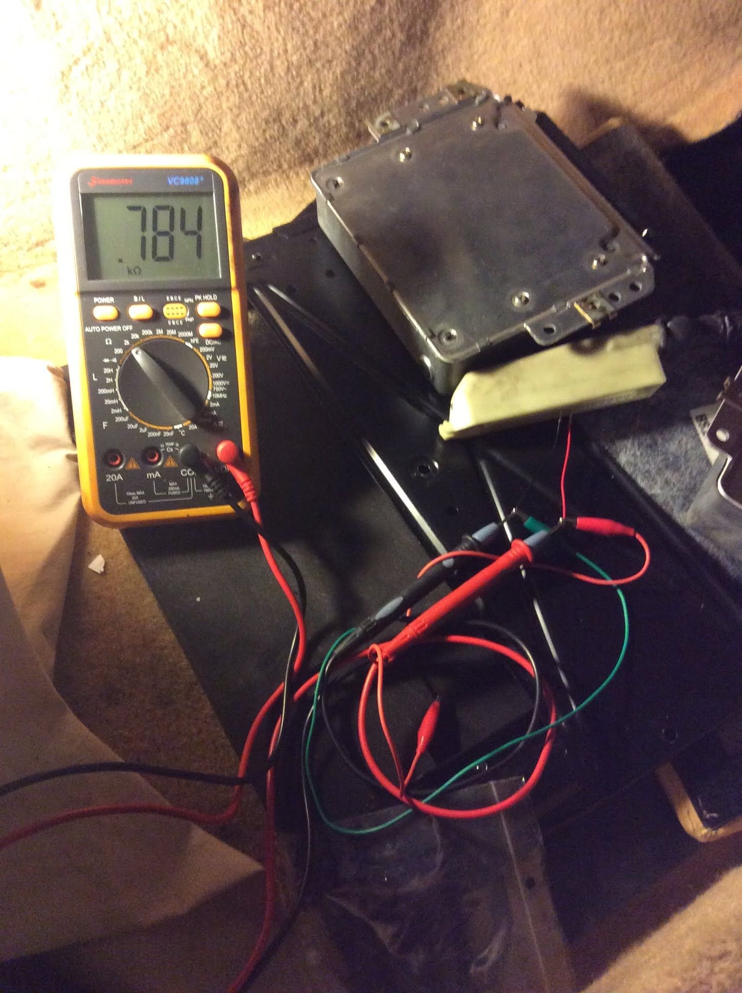
How come I show some voltage on the continuity test (but no beep)?
My guess is that your continuity setting is really a diode checker and is displaying the voltage drop between the two pins. Set the multimeter to ohms and see if you get a reading. It should remain open, but I'm guessing you'll get a reading in the hundreds or so, indicating the wires are touching inside but not getting a clean connection due to corrosion, etc.
I'll check the resistance for sure; but.. exciting news... DarrenD is coming by tomorrow with a working DME! The mystery of the DME should be solved... stay tuned!
Sorry about that, I'm sure that's a bummer, but you dug your way out of a deep rabbit hole so that's good! I was actually suggesting that you disconnect the sensors and the dme and see if there are any ohms between the wires in the speed and ref connectors pins-- i.e., to see if there are any shorts inside the harness. What exactly were you testing? Despite photo quality rivaling most UFO films, Bigfoot sightings, and alien bodies collected in the 50's, I can't quite make out which pins your leads are connected to, and am curious if the speed/ref connectors are connected or disconnected under the hood? I just pulled out a spare sensor and it measures almost exactly 1000 ohms across the two primary signals (just like Clarks says it should). I also tried all combos of the grounding shield, casing and signals to see if something is close to what you are seeing and couldn't get anything like that. Seems unlikely you'd have two identically bad sensors (unless you bought the wrong ones?), so maybe your testing was set up wrong. It also seemed like you were getting a good speed sensor signal on the scope, so I'm guessing you were just testing wrong.. somehow... See Clark's approach linked below.
I'd test per Clark's and if everything tests as it should, and you have no shorts or breaks in the harness, then I'd be inclined to triple check the gap on the ref sensor. Hang in there, I'm weirdly invested in seeing you through after all this.
Unless anyone has any better ideas, [EDIT: posted before receiving Tom's ideas above; those are great--thanks Tom!] I will go back and work on testing the ignition coil--something I hadn't gone back to yet.
Tonight, I am studying my last three ref videos more. It seems on the 2ms & 10ms the dot moves too quickly on the screen to capture more than one pulse (it appears to capture 1 in different spots). I am not sure why the other guy's video manages to only show the pulse in the middle of the screen; trigger still means the dot moves in time across the screen? My understanding of trigger is that it shows nothing until a signal appears, which is what I seem to be getting with the .5s.
I did notice that without trigger, as soon as I touch the probe, some signal appears across the screen. I take this to be noise of some sort?
As the ref sensor has "1 pulse per revolution", at 200rpm that would be once every 60s or 60,000ms. [EIDT: Clearly, it is too late for this type of thinking. Geez..... ignore the following] Since my scope screen has 10 divisions across, if I set it to 1s/div (I can't), I would see six pulses; at .5s, 12. It's pretty tough but I count 11, maybe 12 on the .5s 1v video.
At 10ms/div, obviously the time is moving too quickly to capture even 1 pulse properly, no? That would explain the erratic videos at fast speed.
In anticipation of tonight's DME swap, I picked up my DME from "the guy" who, incidentally, didn't get to it yet. If my coil tests prove inconclusive, perhaps I'll start tracing this reference signal into the DME as Tom suggests.
Last edited by Dan Martinic; 03-27-2018 at 10:58 PM.


 03-24-2018, 09:02 PM