DME destroyed?
#182
Advanced
Join Date: Apr 2018
Location: Slightly left of Vernon, BC
Posts: 74
Received 0 Likes
on
0 Posts
Holy Crap Dan! I just finished reading your epic adventure, it was a 2 beer read.  You have really done a ton of work and I can't believe it's still not running. Lot's of great guidance from many members as well, great to see. I am great with electronics, but just learning Porsche's so your thread may help me get mine going once all of the fuse and relay corrosion is cleaned. I'll keep monitoring your progress and help if I can with the electronics side of things. Glad you learned the scope stuff, great tool to have and know how to use. Oh and you have probably figured this out by now, but 800 ohms is indicated as .800 K on your meter, which is .8 of 1,000, or 800 ohms.
Cheers
 You have really done a ton of work and I can't believe it's still not running. Lot's of great guidance from many members as well, great to see. I am great with electronics, but just learning Porsche's so your thread may help me get mine going once all of the fuse and relay corrosion is cleaned. I'll keep monitoring your progress and help if I can with the electronics side of things. Glad you learned the scope stuff, great tool to have and know how to use. Oh and you have probably figured this out by now, but 800 ohms is indicated as .800 K on your meter, which is .8 of 1,000, or 800 ohms.
Cheers
#183
Drifting
Thread Starter
Not sure if this will help you but some additional info
http://www.roguetuning.com/crank_angle_sensors
http://www.roguetuning.com/crank_angle_sensors
#184
Drifting
Thread Starter
Kilohertz... next week, when the new sensors arrive, if this car starts up, it will be a few more than 2 pints on my end 
Thanks for the clarification; I did figure that one out, but it's always nice to get a lesson!
Say.. any idea why, when reading my ignition coil--no wires attached--with my fancy meter I get a negative reading while the more economical meter with auto ohms scale reads the correctly? See Post #129.
When I test both meters on a simple resister, they read fairly equally. What's up with the negatives? Perhaps my fancy meter is lousy at tiny resistence values?
#185
Advanced
Join Date: Apr 2018
Location: Slightly left of Vernon, BC
Posts: 74
Received 0 Likes
on
0 Posts
Kilohertz... next week, when the new sensors arrive, if this car starts up, it will be a few more than 2 pints on my end 
Say.. any idea why, when reading my ignition coil--no wires attached--with my fancy meter I get a negative reading while the more economical meter with auto ohms scale reads the correctly? See Post #129. When I test both meters on a simple resister, they read fairly equally. What's up with the negatives? Perhaps my fancy meter is lousy at tiny resistance values?

Say.. any idea why, when reading my ignition coil--no wires attached--with my fancy meter I get a negative reading while the more economical meter with auto ohms scale reads the correctly? See Post #129. When I test both meters on a simple resister, they read fairly equally. What's up with the negatives? Perhaps my fancy meter is lousy at tiny resistance values?
Now to your engine, I woke up this morning thinking about this, and all you have done. I don't know how the flywheel is mounted on the crank, but if it is not keyed, could it be mounted "out of time"? ie those studs that give the signal to the sensors could be incorrectly timed. You may be getting spark but the rotor is firing into a blank spot on the cap. Just throwing that out there. I would imagine there should be some method of timing it correctly though. It sure looks like it should be firing with scope signals I saw. I'll check the service manual this morning, work has been rained out.
More later.
Cheers
PS Have you tried the basic coil test, black lead powered with 12V, coil to cap wire .25" off of a ground to see if it sparks, then quickly tap the negative side of the coil to ground and you should see a spark jusp the gap. Make sure you disconnect the negative lead on the coil first (green I think?) as that goes back to the DME.
Last edited by Kilohertz; 04-07-2018 at 01:18 AM.
#186
Drifting
Thread Starter
I don't know how the flywheel is mounted on the crank, but if it is not keyed, could it be mounted "out of time"? ie those studs that give the signal to the sensors could be incorrectly timed. You may be getting spark but the rotor is firing into a blank spot on the cap. Just throwing that out there. It sure looks like it should be firing with scope signals I saw.
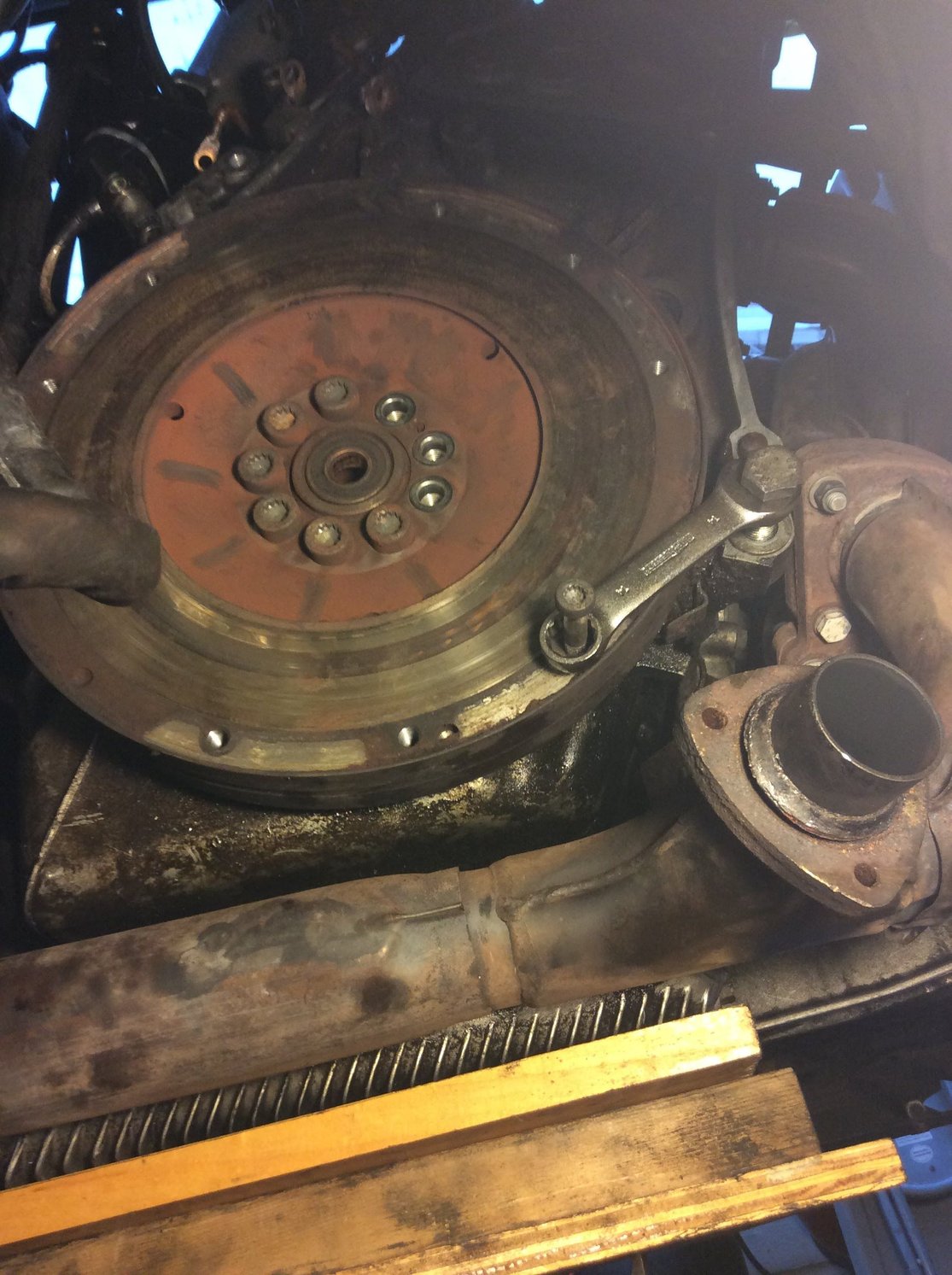
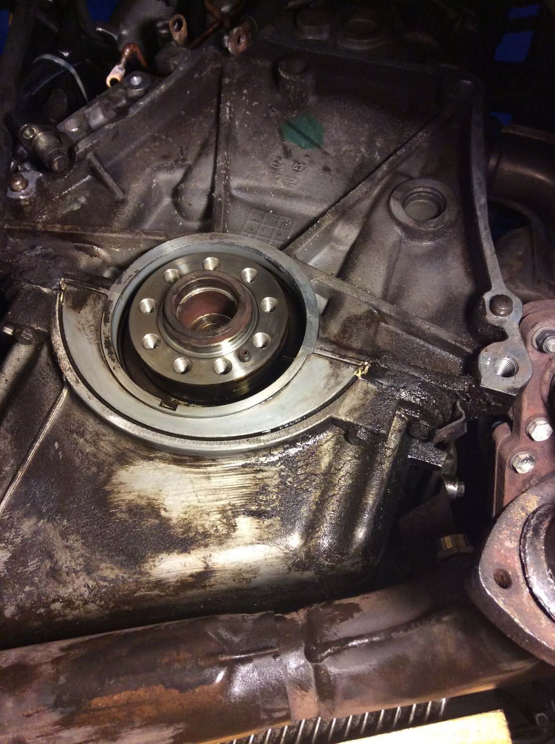
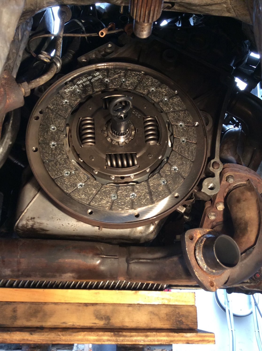
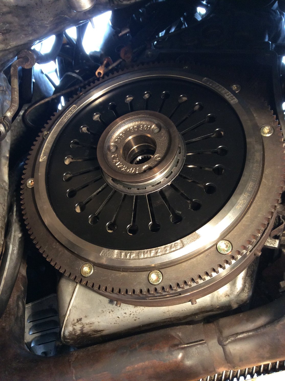
The flywheel is indeed keyed. I followed quite a few tutorials and videos during the clutch install.. can't say for sure, but I think I did pretty good on that side. I even used a torque wrench and new bolts in that area. As you may have read, I did have a dumb moment of trying to put the bellhousing back on with the sleeved sensor bracket in place; but, I've since confirmed the ref stud appears to be good.
Alan 91 C2 explained that the sine wave must have the bottom curve for the DME to trigger; also, since my scope readings are at the unplugged DME harness, the suggestion is made to plug it in and see if the scope shows the same (probing from the opened rear of the harness). I'm gonna try that this weekend and post the scope screen.
Notice on the flywheel there are three little studs. One is sitting on one side while two are on the other half. It the single one that gets read by the ref sensor; the other two get read by the TDC sensor which just terminates in an unconnected plug in the engine compartment and is apparently for diagnostic purposes (ie. hook up to some meter).
One thing to note: the ref sensor stud is pretty far from the "OT" marking, so it doesn't represent TDC. For that matter, the TDC studs are also not on the OT mark--and there's two of them? Odd.
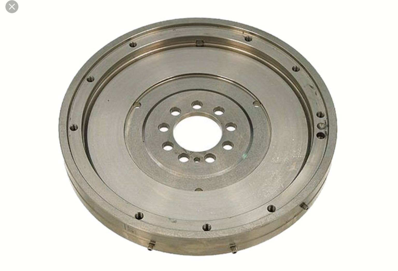
Last edited by Dan Martinic; 04-06-2018 at 12:07 PM. Reason: Cropped photo
#187
Rennlist Member
Hi Dan. All of my meters are Fluke, and once in a while they will read negative resistance and that is usually if there is some residual voltage left on the device, ie if there is a capacitor in the circuit. That coil could be holding enough charge to give you a false reading. One thing to try, measure the coil with the meter set to Diode/Continuity setting, one click to the left of 200 ohm scale, that uses more of the internal battery voltage and overcomes residual charge. Keep in mind it will give you a reading in volts as it's meant to measure diode forward voltage drop, and will most likely read pretty close to 0. You should get the same results with the blue meter. Also check the battery in your yellow meter, maybe low??
Now to your engine, I woke up this morning thinking about this, and all you have done. I don't know how the flywheel is mounted on the crank, but if it is not keyed, could it be mounted "out of time"? ie those studs that give the signal to the sensors could be incorrectly timed. You may be getting spark but the rotor is firing into a blank spot on the cap. Just throwing that out there. I would imagine there should be some method of timing it correctly though. It sure looks like it should be firing with scope signals I saw. I'll check the service manual this morning, work has been rained out.
More later.
Cheers
PS Have you tried the basic oil test, black lead powered with 12V, coil to cap wire .25" off of a ground to see if it sparks, then quickly tap the negative side of the coil to ground and you should see a spark jusp the gap. Make sure you disconnect the negative lead on the coil first (green I think?) as that goes back to the DME.
#188
Rennlist Member
The flywheel is indeed keyed. I followed quite a few tutorials and videos during the clutch install.. can't say for sure, but I think I did pretty good on that side. I even used a torque wrench and new bolts in that area. As you may have read, I did have a dumb moment of trying to put the bellhousing back on with the sleeved sensor bracket in place; but, I've since confirmed the ref stud appears to be good.
Notice on the flywheel there are three little studs. One is sitting on one side while two are on the other half. It the single one that gets read by the ref sensor; the other two get read by the TDC sensor which just terminates in an unconnected plug in the engine compartment and is apparently for diagnostic purposes (ie. hook up to some meter).
One thing to note: the ref sensor stud is pretty far from the "OT" marking, so it doesn't represent TDC. For that matter, the TDC studs are also not on the OT mark--and there's two of them? Odd.
I didn't realize you had the flywheel off, but not even sure you can put it on wrong, since it's keyed as you say. And, if you managed to get it on wrong, you'd probably have smashed valves into pistons by now.... But if there's any doubt, it's easy enough to confirm by pulling out #1 spark plug and confirm with a wooden dowel the piston reaches its high point when the flywheel shows TDC.
#190
Drifting
Thread Starter
Since the spark generally fires somewhere between (say) 5 to 35 degrees before TDC, accuracy is increased by giving the DME its reference check just before that. In other words, if the mark were at TDC, the DME would need to calculate and/or count speed sensor ticks for 350 degrees to fire #1 at 10 degrees before TDC. By putting the pin 50-60 degrees before TDC, it has a more recent check point for higher accuracy..
#191
Advanced
Join Date: Apr 2018
Location: Slightly left of Vernon, BC
Posts: 74
Received 0 Likes
on
0 Posts
Dan, clutch job looks great. car looks nice, even sitting on jack stands. I sure hope you get this going soon. I'll be working on mine this weekend...it's a no start as well, but I bought it like that so I am starting WAY deeper in the hole than you. All I was told was "it ran the last time it was started".

Cheers
#192
Drifting
Thread Starter
Thanks! I've been meaning to show it off lol
Good luck this weekend. If I was staring at a 944 no-start, now I would likely start with fast951's simple checks from post #87:
"Starting fresh makes sense. I hope you already removed the fuse for the Fuel pump, before all the speed/Ref tests. If the injectors are firing, you could fill up the cylinders with fuel. Removing the fuse keeps the fuel out of the equation while checking the injectors and ignition.
- remove fuse for pump
- make sure you are getting 12V at DME
- check injectors pulse with LED or noid light.
- check ignition pulses at coil with LED (black is + green in -) "
The LED is a very useful tool to have! I am looking for the day when I see mine flashing
EDIT: Here is a link to the official Test Plan: http://www.arnnworx.com/dme-data.htm . Also, I have no idea who these people are, but I stumbled upon this diagnostic information and find it to be quite relevant and helpful: http://www.systemsc.com/diagnostic.htm
Last edited by Dan Martinic; 04-07-2018 at 08:38 AM.
#193
Drifting
Thread Starter
On another thread, just received word that another set of new FAE sensors shows this inconsistency:
"I tested one FAE sensor - no continuity on all three pins to the sensor housing.
The other FAE has flashes of continuity on two of the pins. Not sure what this means."
Post #19 on this thread: https://rennlist.com/forums/924-931-...l#post14924781
He has yet to try them. I'm very curious what will happen when he does!
#194
Rennlist Member
Dan,
The reason the meter gives strange values, apart from the EE explanation. Is the meters are designed to read DC and RMS AC voltage. Not designed for anything other than DC or 60Hz (and 50/400Hz, sinusoidal signals). The circuitry does not know how to handle intermittent pulses, from the Ref Sensor.
Flashes of continuity occur when there is capacitive values, like a capacitor, between the conductors. All parallel wires have small capacitive values, usually not measurable with handheld instruments. Measurable capacitive content will shift the wave form to the DME.
Try not to get side tracked on tangential issues. The Ref sensor is your primary problem, yielding no tach bounce or spark.
Alan
#195
Three Wheelin'
Im Patiently observing your progress, I have two brand new FAE Sensors in the box on the Shelf, The Last post prompted me to throw a meter on them. Here is what I found. No Continuity between the shield portion and any of the pins. There IS however Continuity Between the the middle pin and one of the outer pins. These have never been installed. If I recall I have FAE sensors in my 86. I Do remember the wires were in bad shape, I soldered the wires back together but the car still wouldn't start. When I put new sensors in it fired right up. You will Get this, keep plugging away...


