When you click on links to various merchants on this site and make a purchase, this can result in this site earning a commission. Affiliate programs and affiliations include, but are not limited to, the eBay Partner Network.
Alan_91_C you had me at "You are very close to solving this" That's some interesting electronics info though!
Perry.. this morning, I completed my order (also from Ian) by adding the "Bosch" reference sensors. My understanding is that these are the ones with the longer cables but otherwise the same. I hope so.
The shipping order has already been done; harness included. Oh well, good to have I suppose... though I also try to stay away from disturbing what is working.
Just plain strange that the scope shows the same shape even when the non-continuity sensor is in the reference position. This route will be revealed when the parts arrive.. stay tuned!
Yeah, that's what was so misleading about all the work that I performed. I kept testing the sensors and the tests kept coming up good. Both sensors produced the correct internal resistance, the correct cranking AC voltage, they produced the correct sine wave with an amplitude of 12 volts (for the speed sensor), produced a single spike with an initial positive slope (for the reference sensor), yet the car wouldn't start. Using the factory flow chart diagnostic, I concluded that my DME and KLR were bad and had them rebuilt by ECU Doctors in Florida. That was an $800 hit that I most likely didn't need to take. Eventually I figured out that the FAE sensors had continuity between the metal shield end and one of the pins whereas the oem Bosch ones did not.
You might, as a diagnostic test, cut off those shields and see if the car will work. That costs nothing.
Perry,
I recently went through this exercise with my 86 951. The car engine just died 5 miles from home after a North GA run of over 100 miles.
I expected the sensors as no tach bounce. Installed two new FAE sensors. Still no start. Looking at the Ref signal, pin25+ and pin26- realized the wave started neg to positive. (previous owner rewired the sensors to the DME) Swapped wire pins 25 and 26, and vroom. (I did ohm out the sensor connector to DME connector, and found REF connector was wired in reverse, just to confirm the Oscope analysis.) The old sensors had just the wires and spade crimp, as the actual connector disintegrated. Will have to look, i think the rewire only used two conductors.
Alan
Yeah, that's what was so misleading about all the work that I performed. I kept testing the sensors and the tests kept coming up good. Both sensors produced the correct internal resistance, the correct cranking AC voltage, they produced the correct sine wave with an amplitude of 12 volts (for the speed sensor), produced a single spike with an initial positive slope (for the reference sensor), yet the car wouldn't start. Using the factory flow chart diagnostic, I concluded that my DME and KLR were bad and had them rebuilt by ECU Doctors in Florida. That was an $800 hit that I most likely didn't need to take. Eventually I figured out that the FAE sensors had continuity between the metal shield end and one of the pins whereas the oem Bosch ones did not.
You might, as a diagnostic test, cut off those shields and see if the car will work. That costs nothing.
Perry
Wow, crazy. Can't imagine FAE intended to do that, nor how they expected the car to run if they did, at least on a 944...
Attached is the sensor to DME schematic.
Note the shields are separate from the induction coil conductors. The continuity was not part of the proper build for the FAE sensor. Manufacturing SNAFU.
Perry, did both FAE sensors have continuity to the shield?
I also remember when i bought the 951 engine, 3 years ago, with DME, it would not start, traced back to grounds 5 and 23 soldered together. Was so frustrated with that work, (had an Autothority upgrade to MAF, but would hardly run, very rich.) Bought a VEMS to install, but decided to try the AFM in the parts i purchased. Started and ran fine. VEMS to be installed someday.
As i recall the grounds tied together showed a lot of noise on the Ref sensor signal.
Last edited by Alan 91 C2; 04-04-2018 at 03:36 PM.
Both FAE sensors had the continuity to the shield. Also, the wiring harness I bought from Ian at 944 Online tied the grounds from pins 5 and 23 together. This has not caused any problems.
Coincidentally, I am currently doing a clutch job on my 1986 911 and am replacing both the speed and reference sensors as the outer rubber insulation is almost completely gone, exposing the braided mesh insulation.
I tested my old FAE sensor against the current Bosch one that came with the car from the factory. The FAE sensor has continuity between its center pin and the metal shield but the Bosch ones from 1986 that are on the car do not. I have just received my new genuine Bosch, made in Germany sensors (RockAuto for $53 each) and they also show now continuity between the shield and any of the pins.
What? Your new Bosch sensors have continuity between the shield and all the pins??
EDIT: lol you must have posted as I was writing
Ok..this is getting wierd.
Curious now what I will get!
Note that I bought both my FAEs in December from the same place (Paragon Parts) and only ONE has the continuity.
This weekend, I'll try to probe the open-back DME harness to see if the signal changes while DME is plugged in. After that, I might cut off the shield from the offending sensor and see what happens.
On a side note, I borrowed a multimeter from work to re-test the coil. This time, I got .7 ohms across black & green terminals. No negative and no dramatic falling of resistance; just a direct reading.
I also did all my resistance tests last night / this morning with the work meter.
I guess my fancy meter is acting all strange, or I'm not using it properly; the work one is a breeze: auto ac/dc and ohms range.
Highly recommended; it's the GTC on the right
Last edited by Dan Martinic; 04-04-2018 at 07:15 PM.
BTW does anyone have a theory why my FAE sensor with continuity, when placed in the B hole (as reference sensor), causes pin 26 to give the same ohms reading to ground (28) or shielding (5) as it does to pin 25?
And doesn't cause any extra ohms readings when placed in D (as speed sensor)?
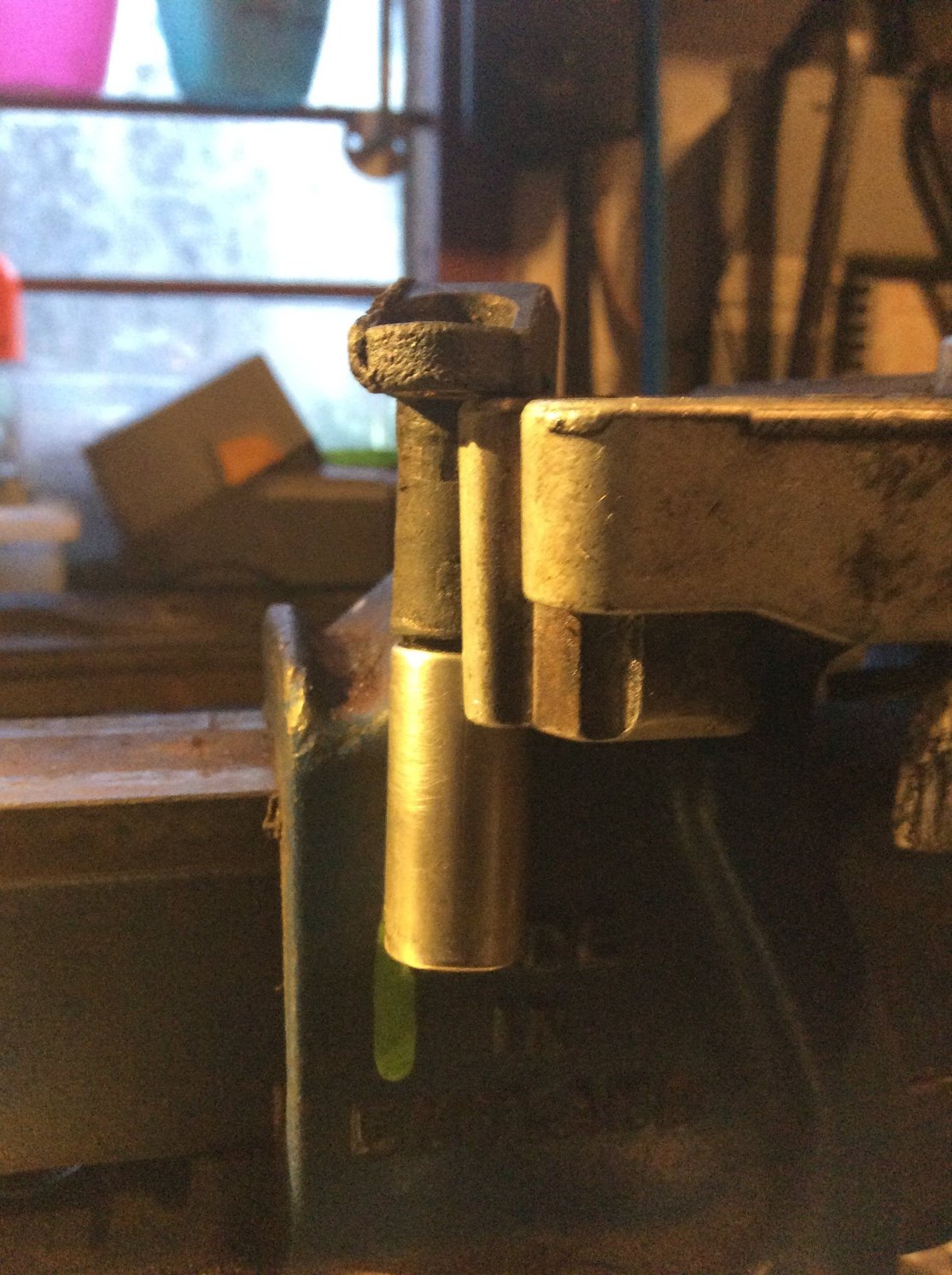
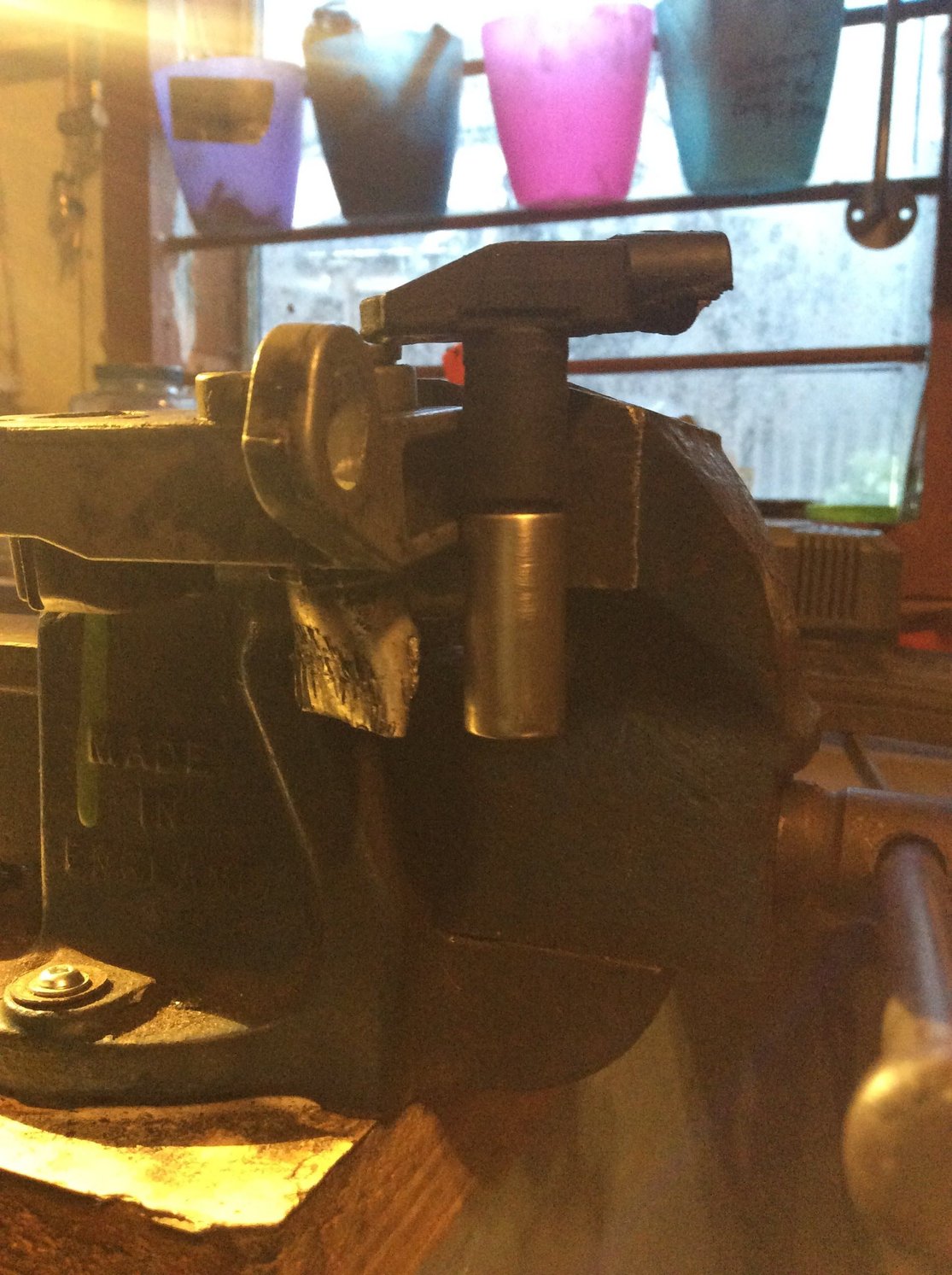
I believe that one of the holes on the mounting bracket allows the sensor to slide in far enough that the metal shield is completely through the hole so that it doesn't touch any metal part of the car, thus being ungrounded.
Here's my original old Bosch sensor lined up against the outer D hole on my original bracket.. and that's without the spacer washer which brings it even higher up
I would show you how it lines up with the B hole and aluminum sleeve.. but... when I pulled the whole original assembly out, after breaking one sensor, the bracket endured some serious beating trying to get the other sensor and sleeve apart. It ain't pretty. Broke the TDC sensor extension and seriously mangled the sleeve.
FYI the original sensors were so badly stuck in there that I can't even put this one back into the hole; the hole has shrunk from.. oh, I don't even know what's in there.
That's why when I installed the new ones, I lathered them in my Molyslip Copaslip anti-seize. Then, wondering why no one seems to be talking about applying some anti-seize in there, I thought maybe that was the problem, so I cleaned the metal shielded halves.. then the whole sensor.
Say.. is it a good idea or bad to use anti-seize on the sensors? They certainly are prone to "difficult" removal......
Yeah, my originals were seized badly too; they seem to have corroded (bonded) themselves with their hole, sleeve or not. I heated them up and banged them out; unfortunately, I also tried removing the aluminum sleeve.
This was a big mistake. Bent the sleeve and broke the bracket's third hole (the TDC sensor one). Should have just left the sleeve alone....
Got lucky and found a good used bracket--with sleeve--from a fellow Rennlist member
I used anti seize on my new ones after having to chisel the bracket out because the non sleeved one never budged.
I'm assuming you don't have sensor issues then? Glad to hear anti-seize won't cause problems; I thought it might, given the metal content.. though I'm using Copaslip which I understand is copper. Obviously, I don't put it on the very bottom of the sensor


 04-04-2018 | 01:45 PM
 That's some interesting electronics info though!