When you click on links to various merchants on this site and make a purchase, this can result in this site earning a commission. Affiliate programs and affiliations include, but are not limited to, the eBay Partner Network.
More work done, though I didn't get as far as I wanted. Oil pan is clean and ready to install. I finally got one rod bearing set inspected. All looked good.
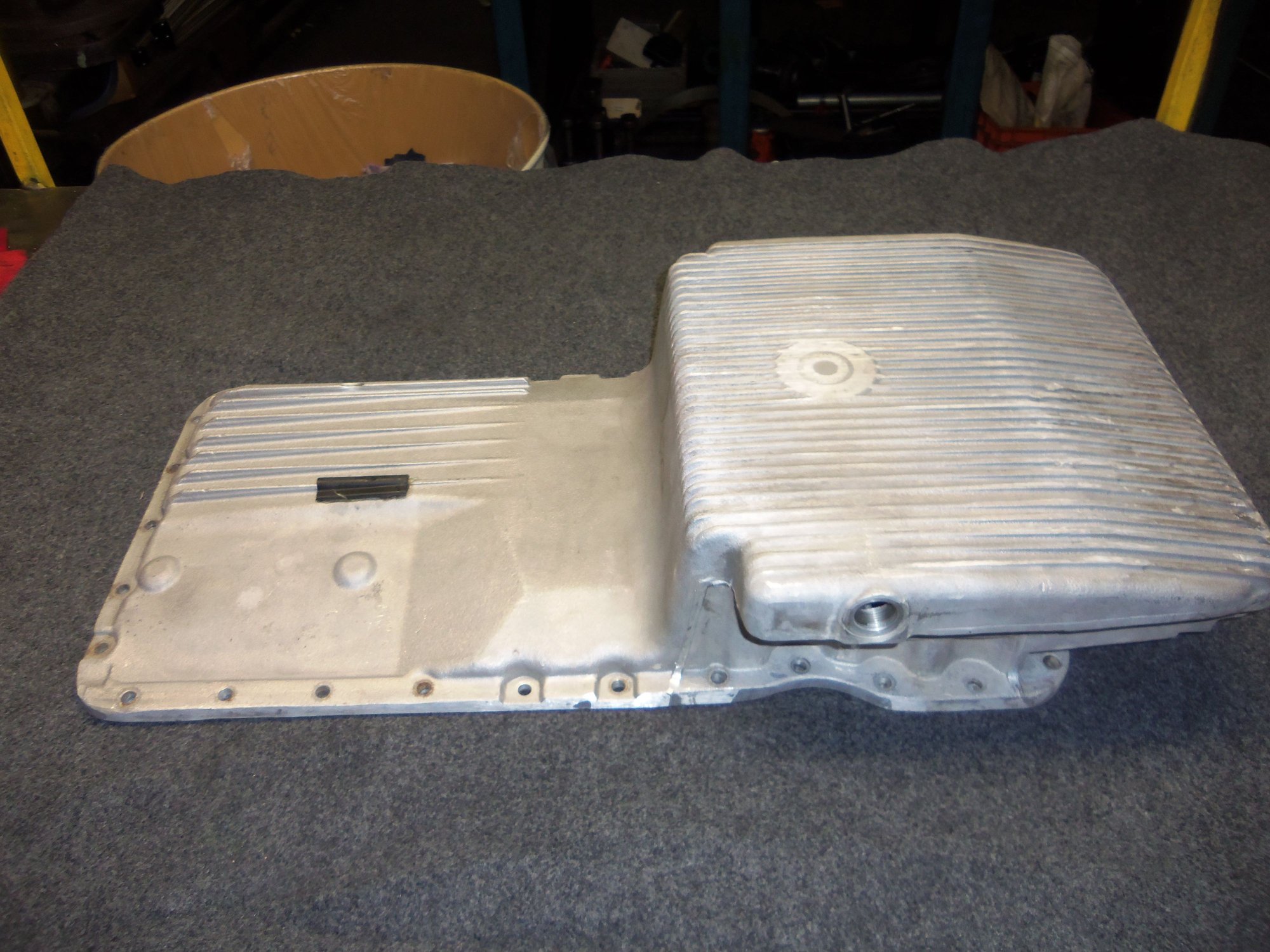
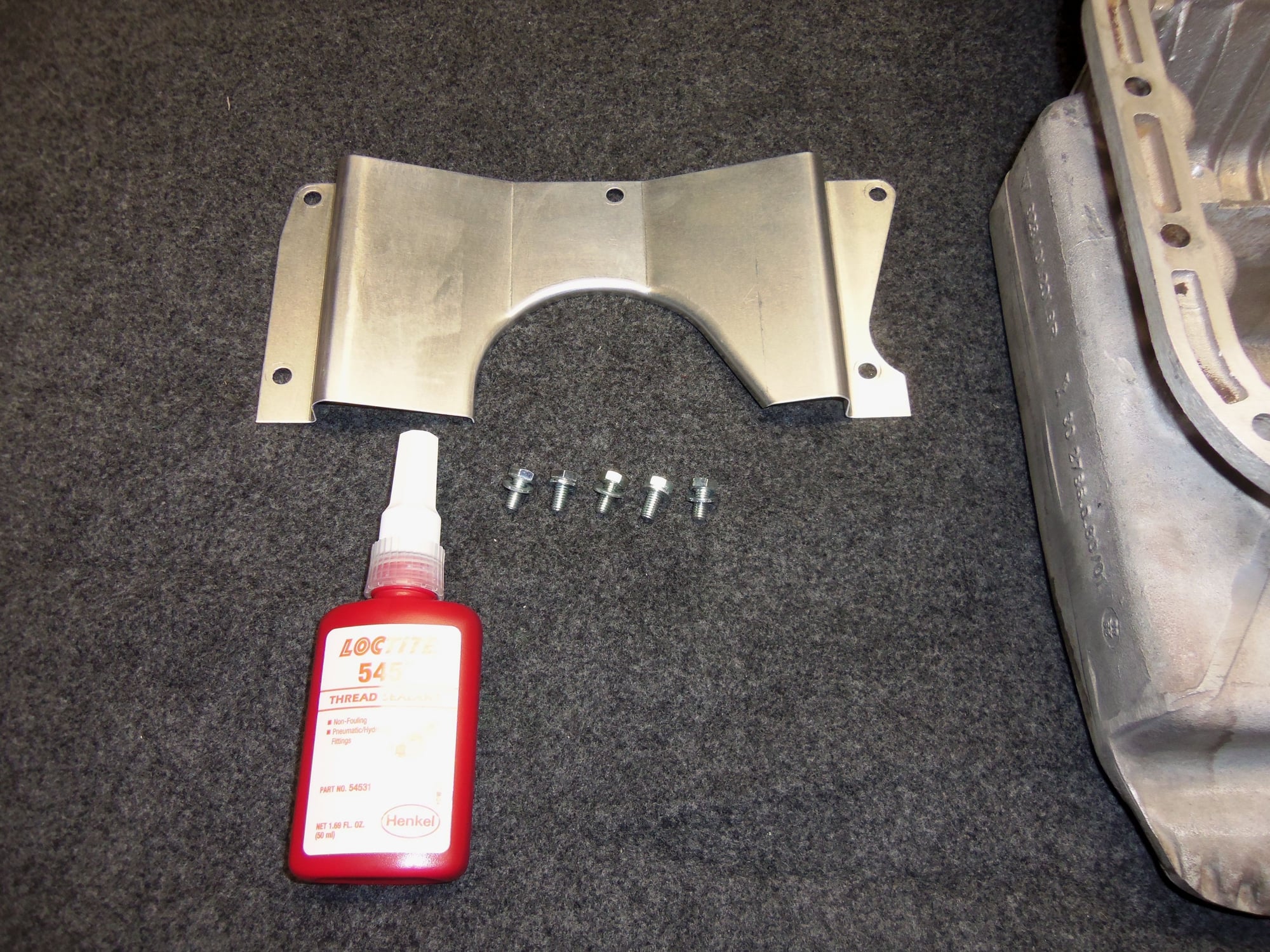
Got the oil pan cleaned and the GTS baffle mounted a few nights ago at work.
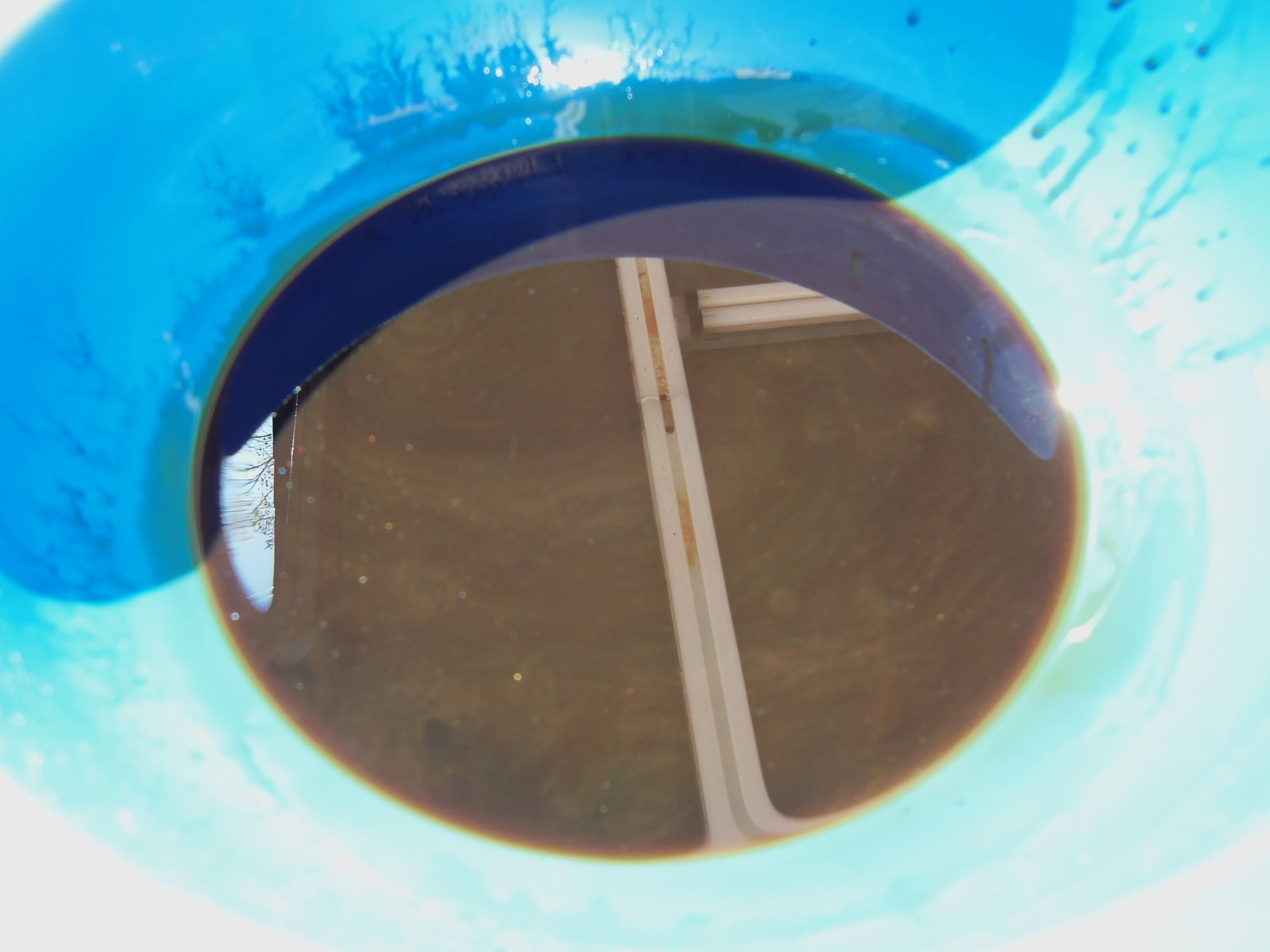
I drained a few ounces of oil out of the sump before cleaning it. In strong sunlight, I could see a slight metallic sheen. But I already knew that. For a moment, I kicked around the idea of sending that to Blackstone Labs for analysis. However, I don't think oil clinging to the inside of the oil pan is a representative sample of the 9qts of engine oil from a 928. I will wait until the next oil change and send a sample off.
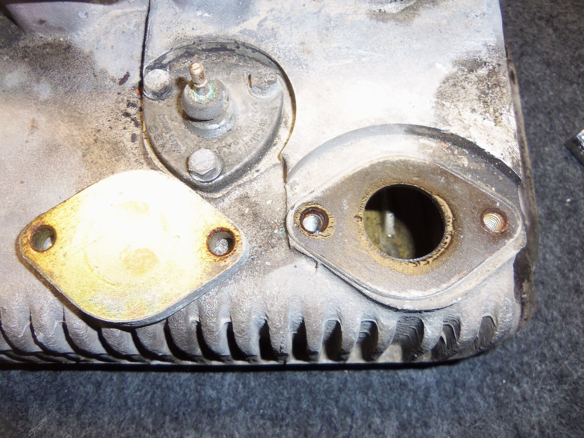
Before soaking the oil pan in the heated parts washer at work, I removed the block off plate and the oil level sensor. That oil level sensor was really stuck on there! I didn't pry on the arm for fear of breaking it. I wedged a razor blade in and around the gasket. Finally got it to break free.
Lots of scrubbing, rinsing, and blowing dry later, the oil pan was quite clean. Not pristine, but serviceable.
I checked PET for the size of the screws that hold the GTS baffle to the oil pan. M6 x 12mm, flange head. I replicated that with hex head M6 x 12 screws and flat washers. I positioned the baffle as far back as it would go. Center punch, pilot drill, finish drill, tap, clean the hole. Repeat four more times.
I let the baffle soak in the parts washer to loosen the label on it. Learned that from Nicole's post way back when.
I installed the M6 screws with two drops of Loctite 545. We use it at work on hydraulic fittings. I chose it because it resists oil. I don't want those little screws backing out. I torqued the screws to 75 in/lbs in two stages.
The completed oil pan has been wrapped up in a trash bag, and will not come out until installation time.
Slight metallic sheen in the oil drained from the sump.
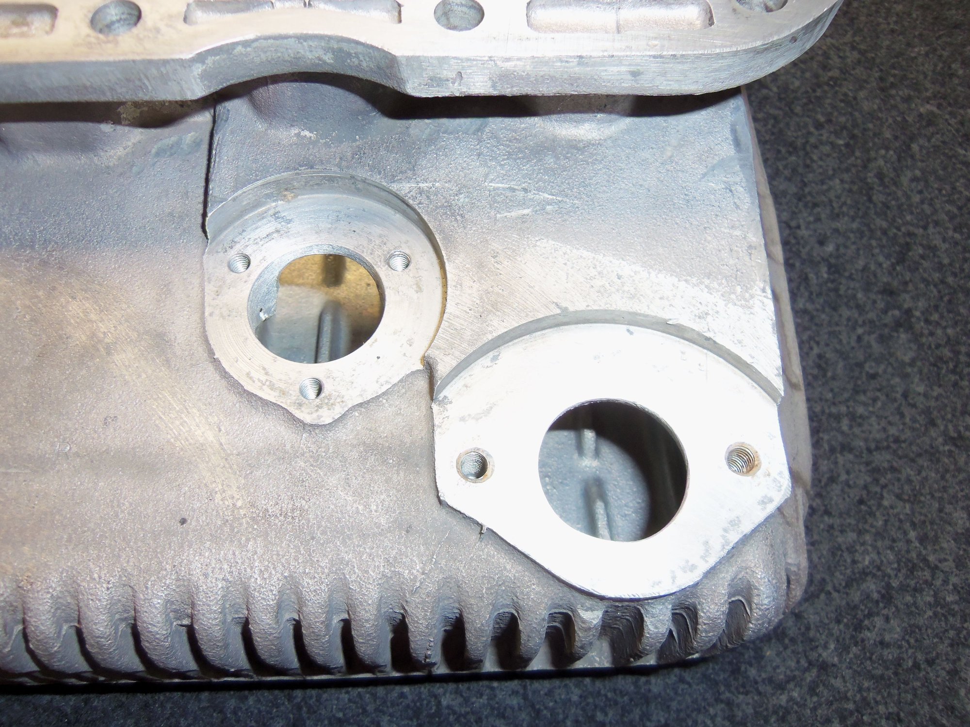
OIl level sensor flange and pre-S3 oil fill block off plate.
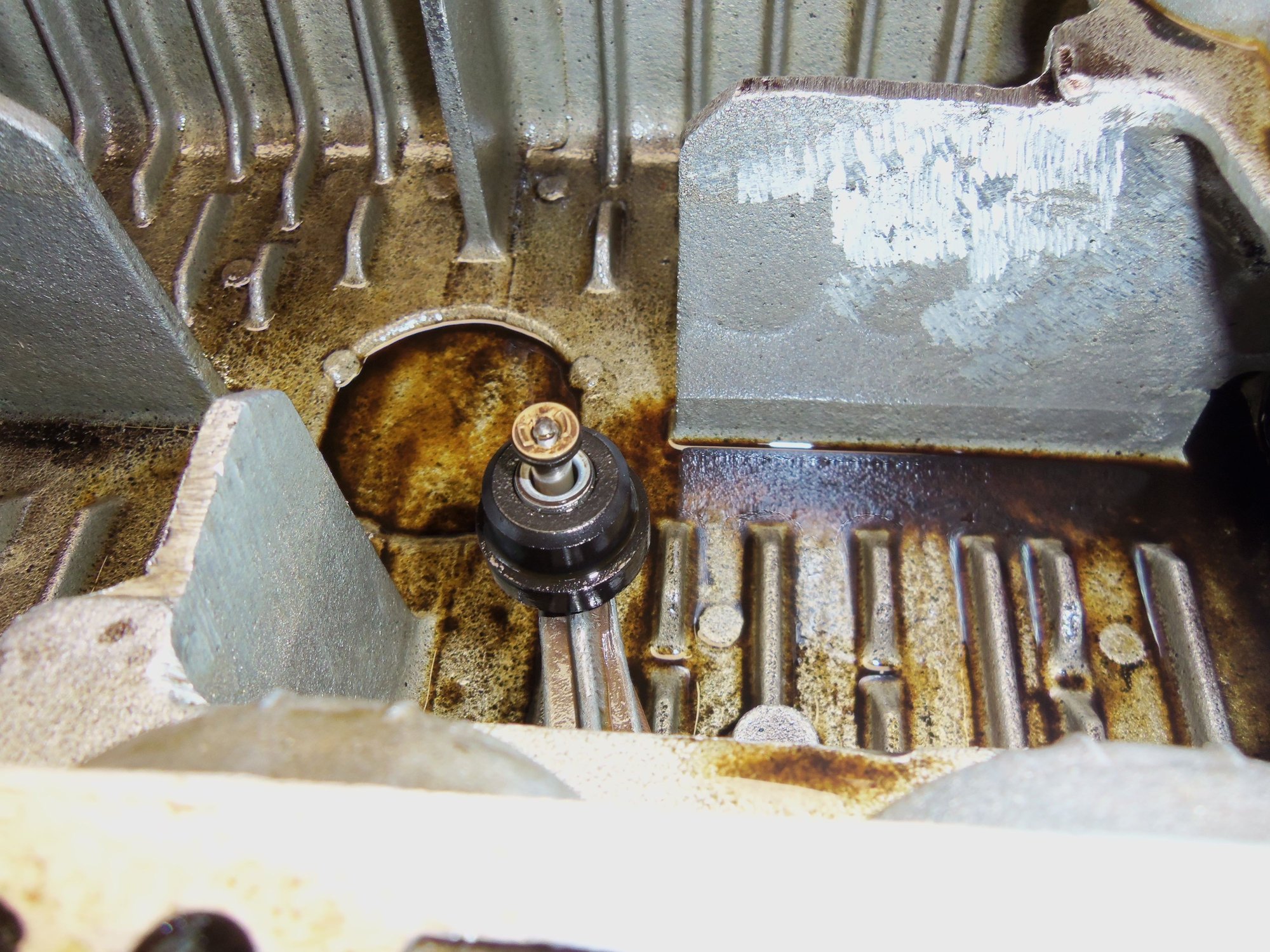
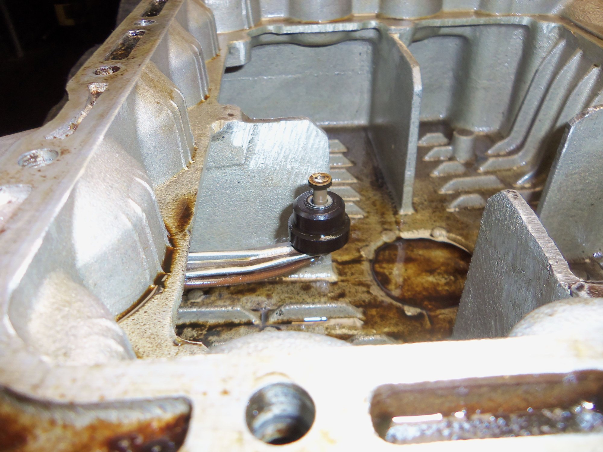
Oil level sensor float.
Oil level sensor arm seems too fragile to pry on.
Plate is thicker than I expected.
Oil pan cleaned up nicely.
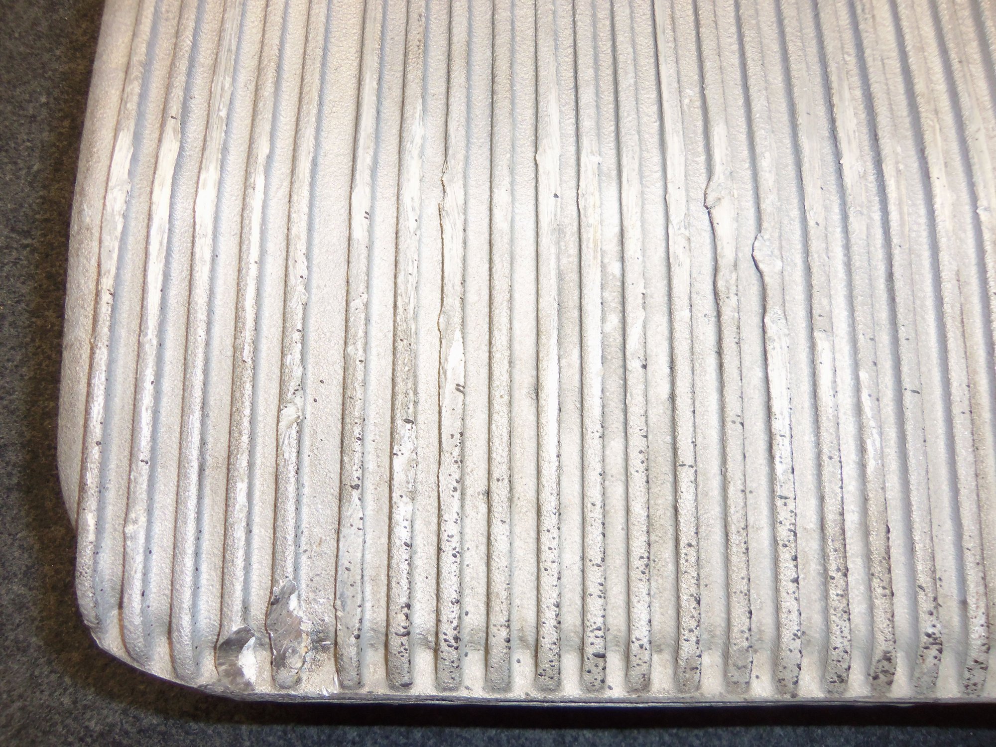
This oil pan has had a hit or two...
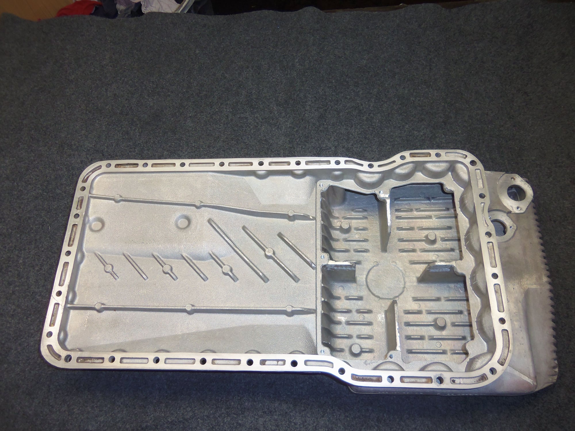
Inside of the oil pan cleaned up very well.
Much cleaner than it was before.
Had to scrape gaskets here with many razor blades.
New GTS baffle with the label removed, Loctite 545, and M6 hardware.
Completed GTS baffle installation.
I should have gone straight on to the connecting rod bearings. Instead I got side tracked fitting the oil pan studs.
Removing the fossilized old cork gasket was much harder than I expected. The gasket was fiercely stuck to the pan rail in between the bolts. I ended up using many razor blades to break it loose. Then, more razor blades to remove all traces of the old gasket.
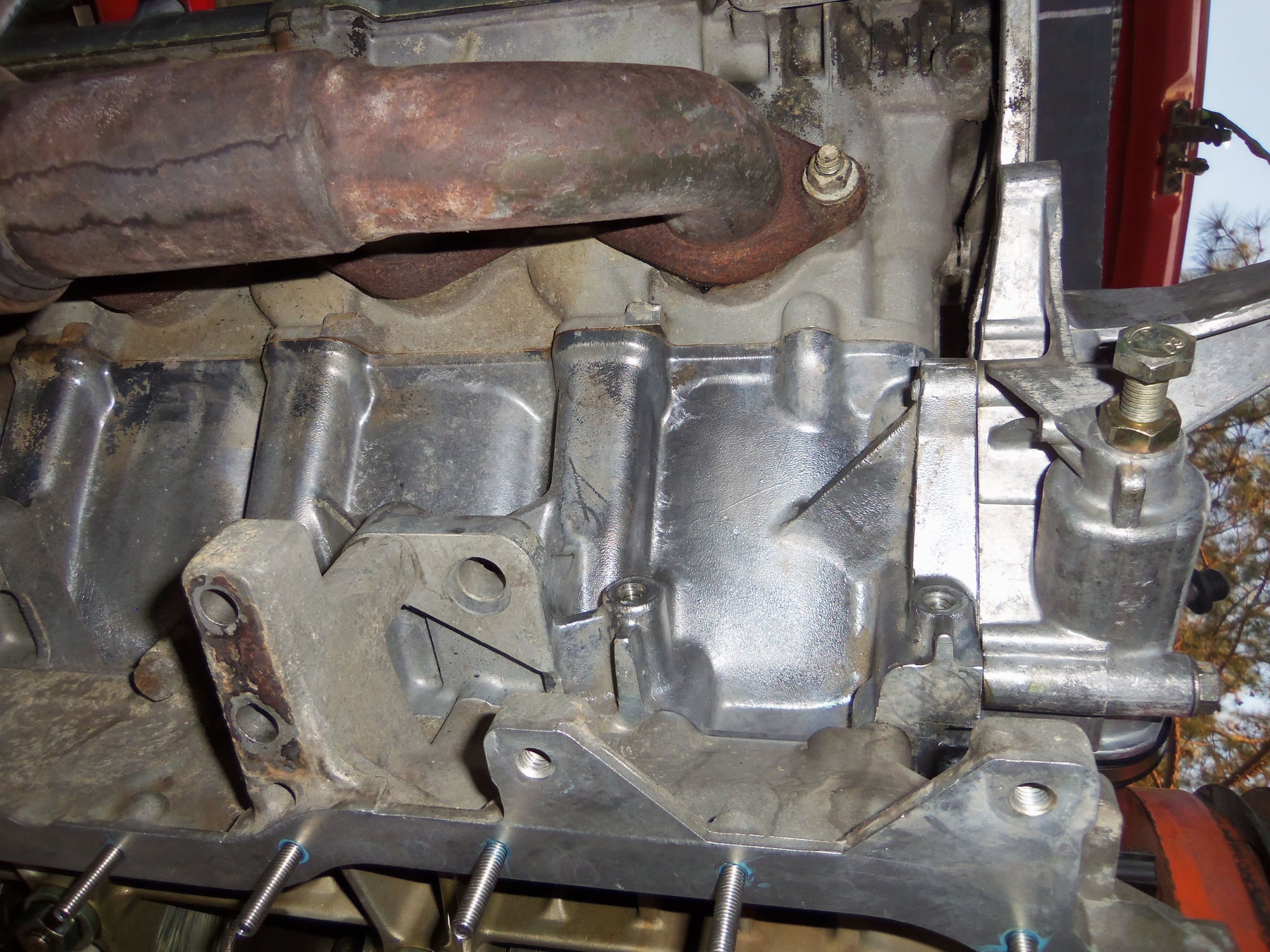
I did some remedial cleaning of the sides of the engine block. For giggles, I filled a little water spray bottle with mineral spirits. It worked great! I sprayed the mineral spirits on the block, and scrubbed with a toothbrush. Labor intensive, not perfect, but it is good enough for now.
I followed up by spraying the inner sides of the crankcase above the pan rails, the pan rails, and all the oil pan bolt holes with brake cleaner. I wanted to remove all the oily residue before I started to set the studs in place with blue Loctite.
Not perfect, but cleaner than it was.
Yeah, I know, I cracked the sealing flange for the upper oil cooler line fitting. I will be doing the 'seal it with JB Weld' trick.
Reading through a few threads on the silicone oil pan gasket and the stud kit, I decided to follow suit and shorten some of the studs.
Most posters shortened five studs: the one above the starter and the four above the crossmember.
I only shortened four studs. The hole above the starter on my block was open. So, I just ran that stud in until it was around 21mm out from the pan rail.
After determining the depressions in the oil pan for the short bolts were 3mm deep, I removed 3mm from four of the new studs. I had to be very careful in dressing the cut off ends so they would thread smoothly into the pan rails. I ended up chasing them with a proper thread die. My normal trick of using a thread chaser still left a tiny burr that got hung up in the pan rail threads.
Before installing the studs, I cleaned the bolt holes and pan rail one last time. I used a lint free cloth on the pan rail. I will do so again just before I actually install the oil pan.
I ran those four short studs in until they were around 22mm from the pan rail. The rest of the studs got installed until they bottomed out, or were around 24mm from the pan rail. All studs were installed by hand with blue Loctite. Since it will be a few days until I install the oil pan, the Loctite will have plenty of time to cure.
Oil pan studs installed and Loctite is curing.
Finally, onto the rod bearings. Due to lack of time, I only got to #1 rod bearing set.
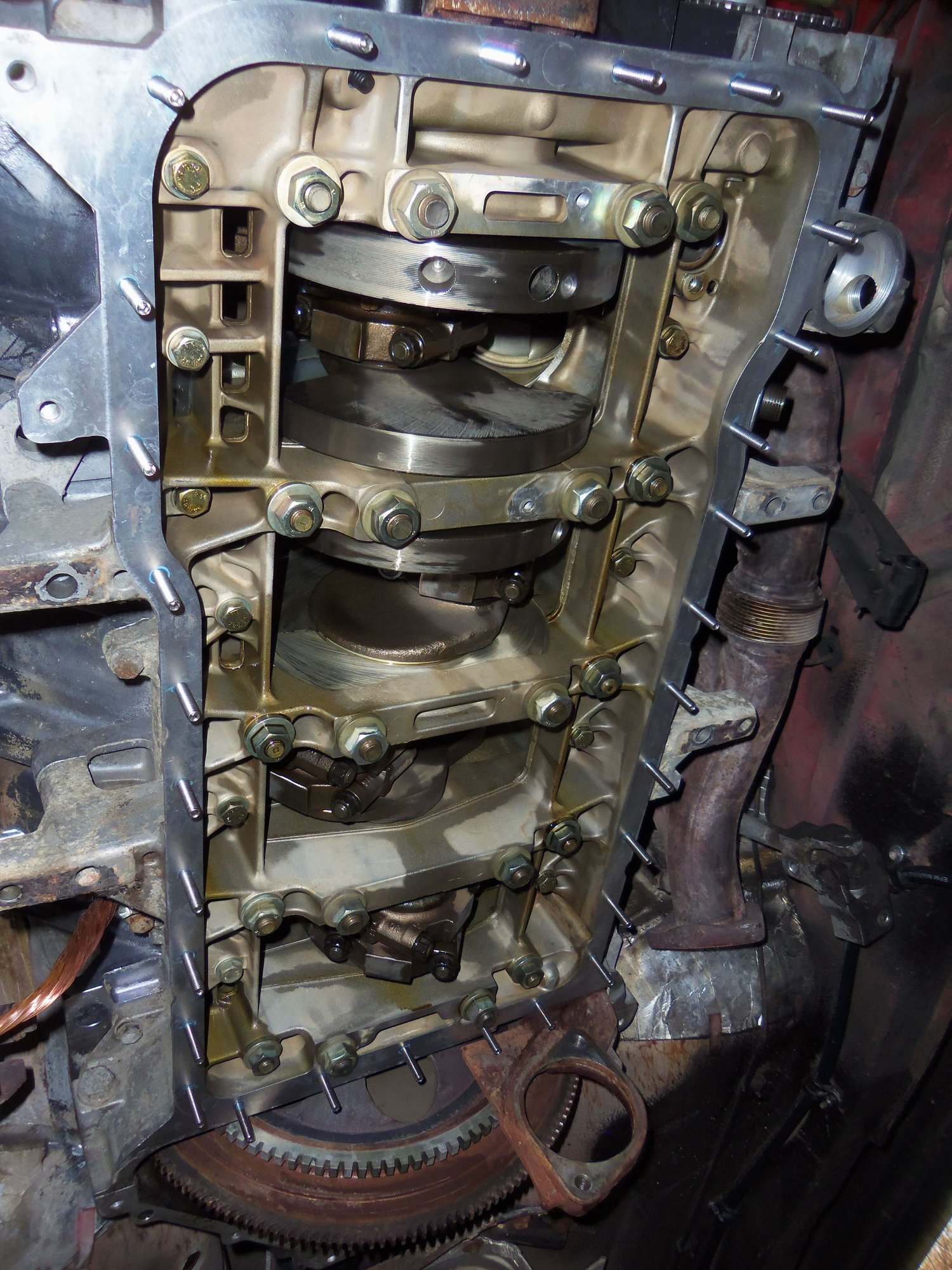
I have disassembled several engines, and built a few. However, I have never pulled rod bearings in situ. It was an experience...
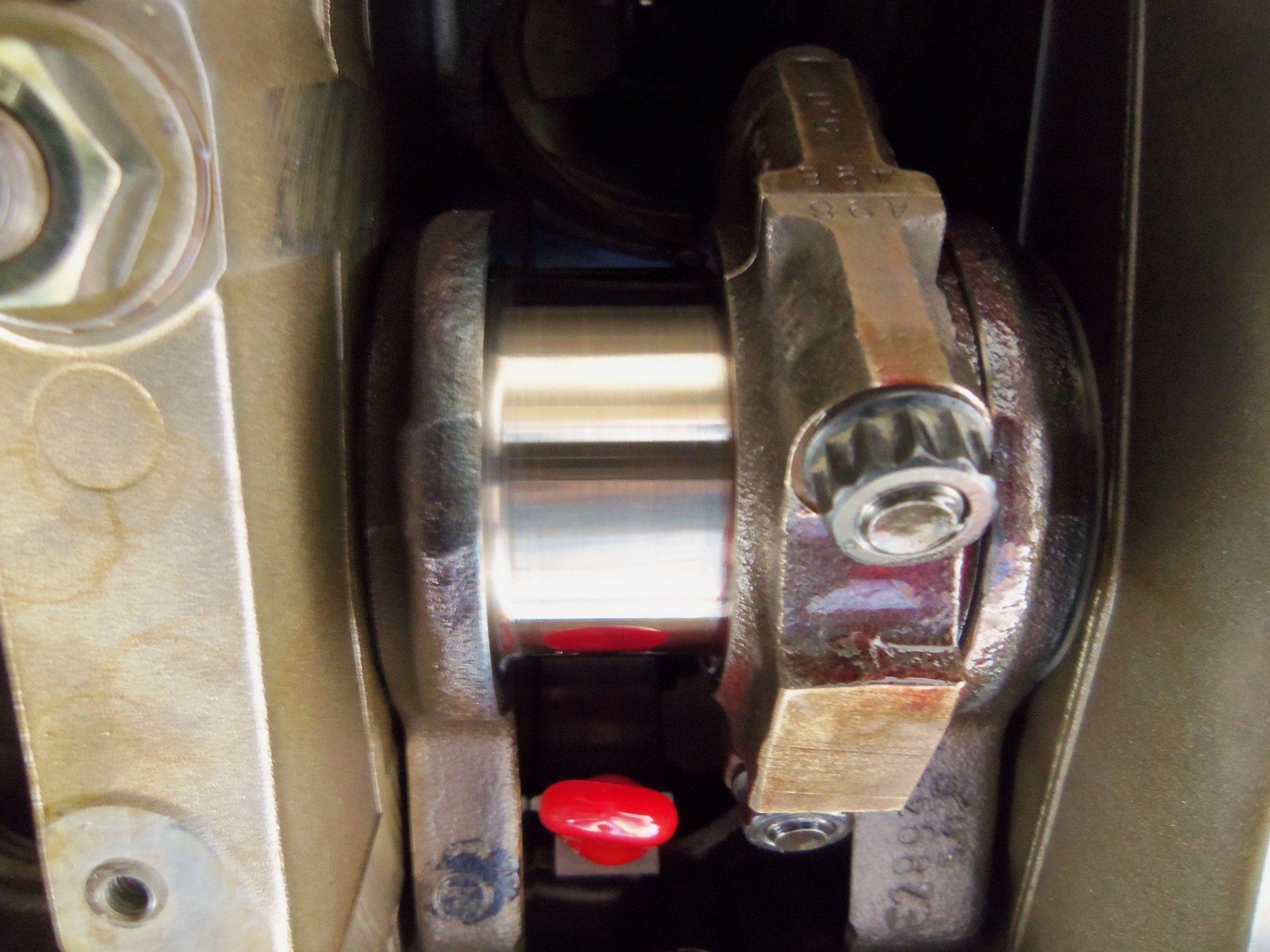
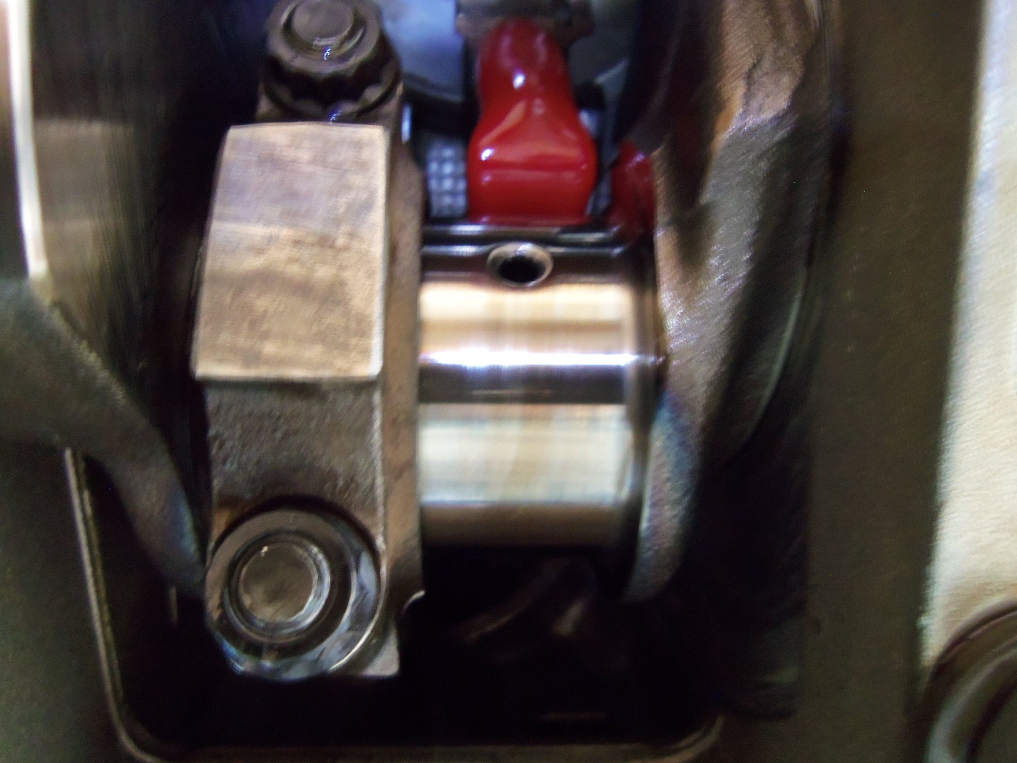
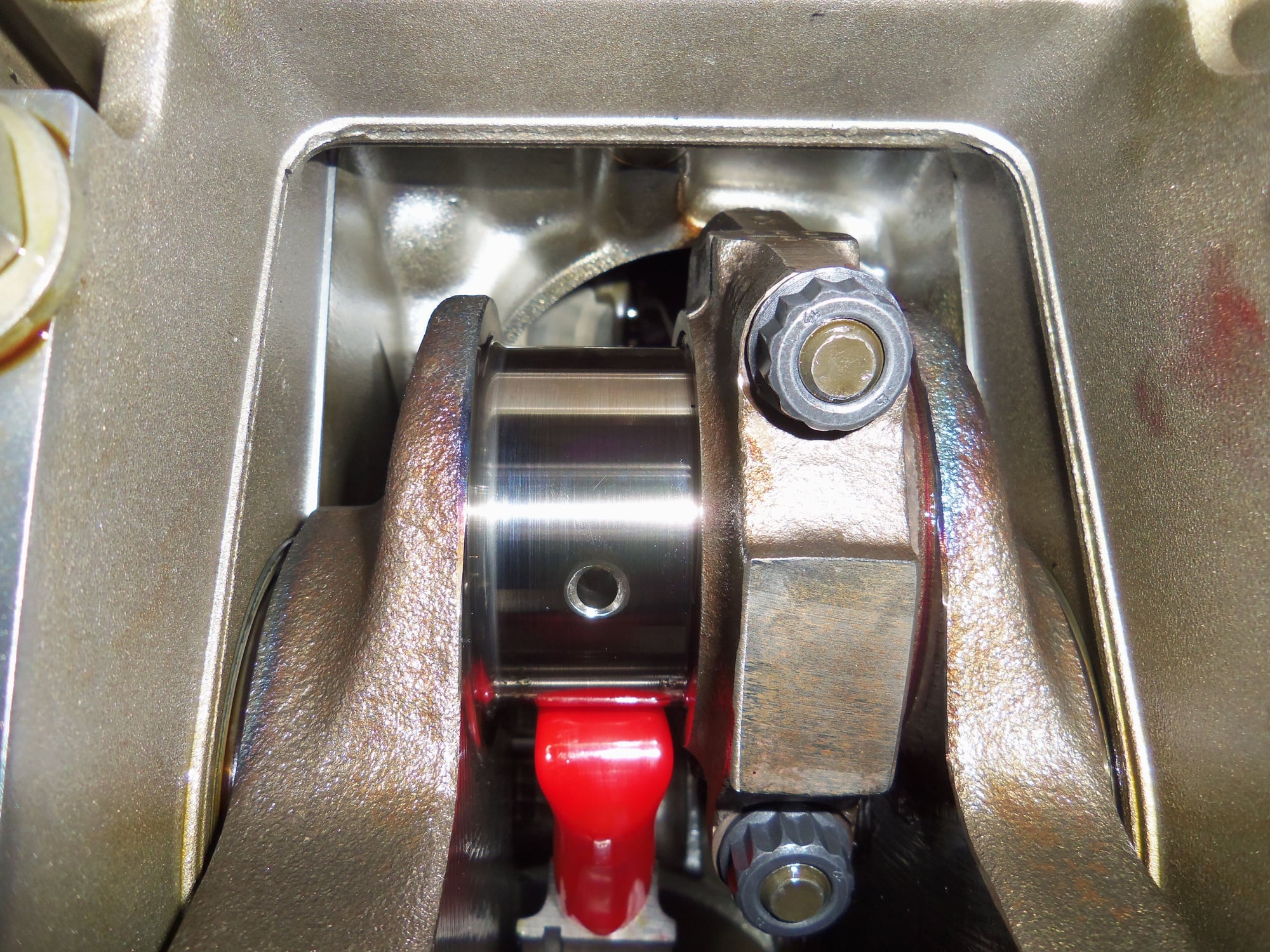
Of course the rod cap didn't want to come loose. I nervously tapped it with a little brass hammer. It came loose. Too bad the bearing shell stayed with the crank. I removed the shell to find a pristine rod journal on the crank.
I kinda expected that. Most of the posts I have read imply you have to do something really stupid and/or try really hard to damage a 928 crankshaft.
I put protective hose on the rod bolts and started the push the rod/piston up away from the crank. And the upper bearing shell fell out of the rod. It took me a few tries to wiggle the shell out.
I forgot that you could gently push the piston/rod high enough that the rod journal would rotate clear.
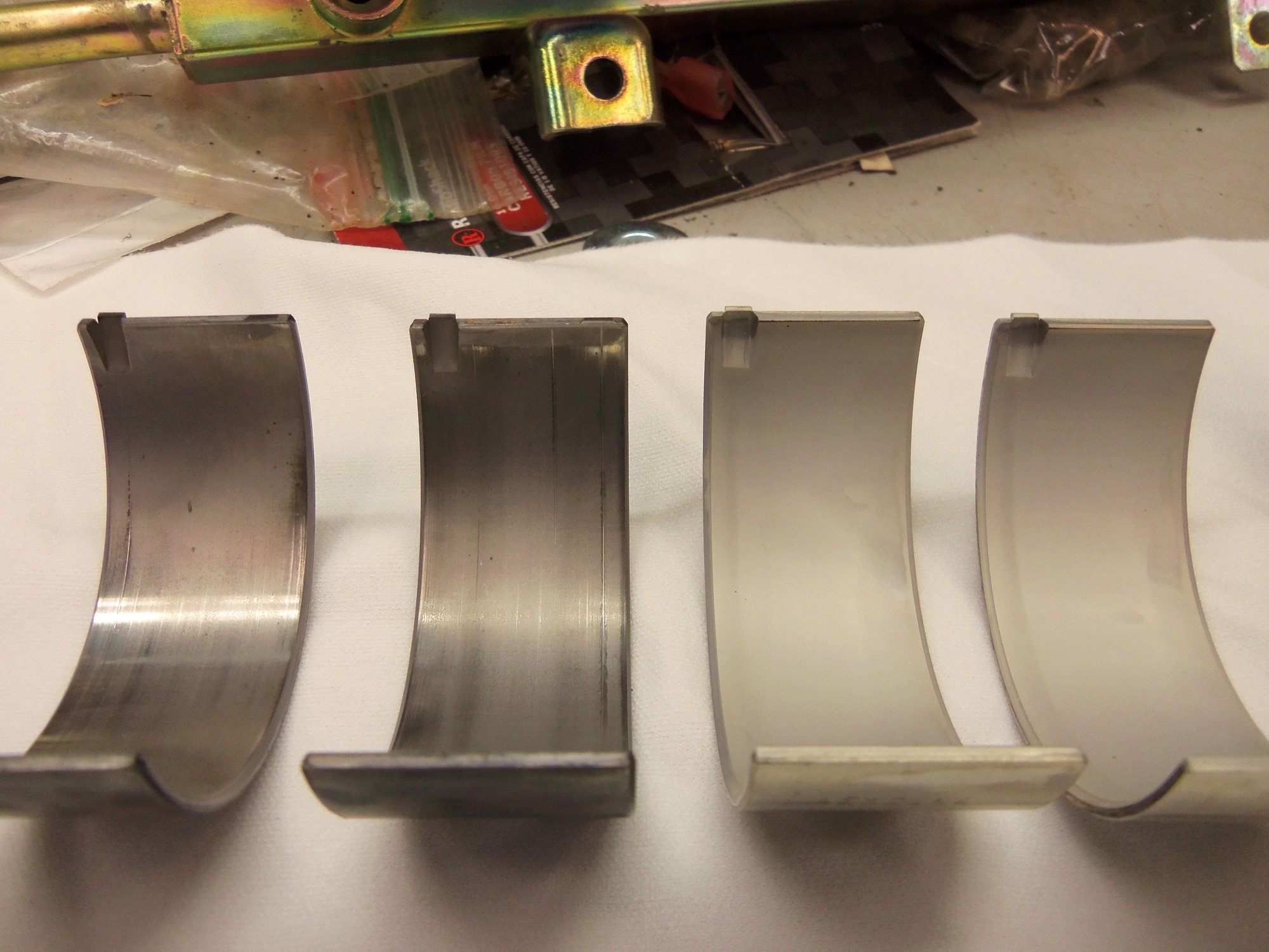
On a lint free cloth, I inspected the rod bearings. Both show wear, but not horrible. I gently cleaned them with brake cleaner and a lint free rag.
back at the engine, I cleaned the rod journal and the bottom of the rod with another lint free rag and brake cleaner.
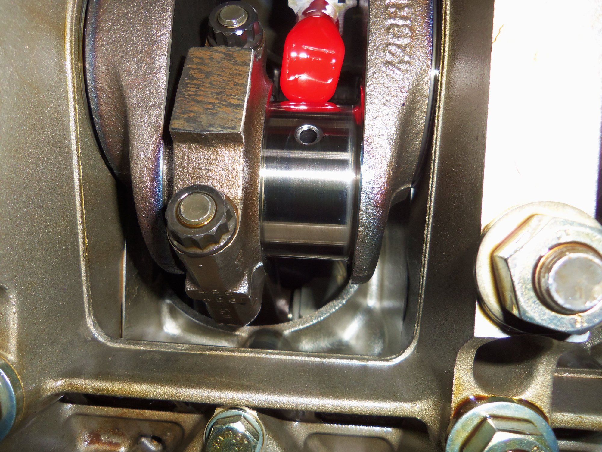
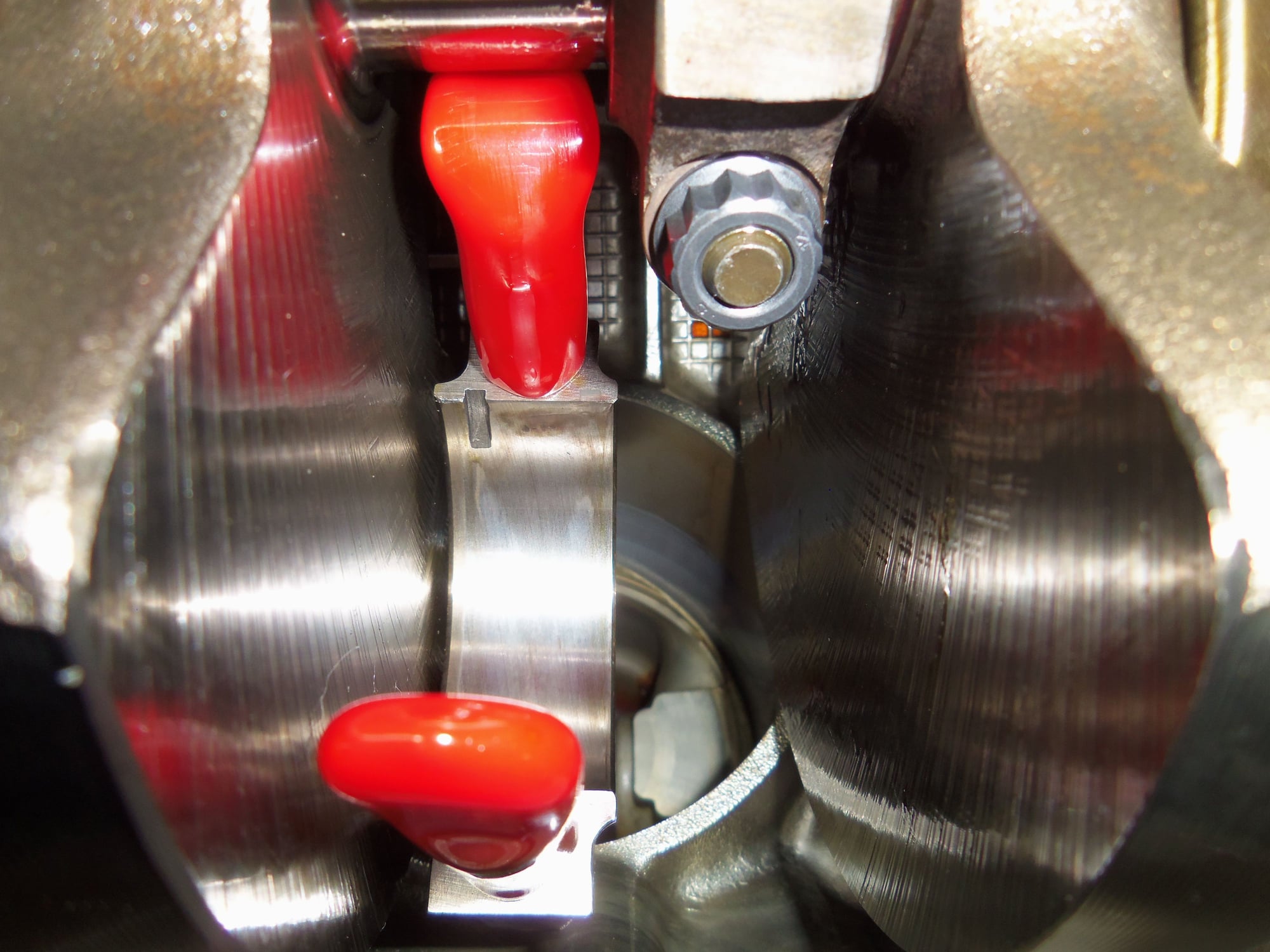
Moment of truth: clearance. It took me a couple of tries to get the upper rod bearing shell back up seated in the rod. Then, I put a piece of green plastigage on the lower bearing shell. I reinstalled the rod cap and torqued the old nuts to 55 ft/lbs in a few steps.
Removed the cap and measured the smashed plastigage. 0.038mm.
Section 13, page 16 of the WSM calls for 0.02 - 0.07mm clearance for a new rod bearing, and 0.10mm wear limit.
Rod #1 is good!
Cleaned the smashed plastigage off the rod journal and bearing with a lint free rag and brake cleaner. Back on with the rod bolt protectors and back up with the piston/rod. Once again I cleaned the upper bearing shell with a lint free rag and brake cleaner, then lubricated it with Permatex engine assembly lubricant. Same thing for the lower bearing shell.
I know the standard procedure is to just oil the bearings. However, the oiling system on the Red Witch is completely dry. I want a little extra insurance for the rod bearings until oil pressure builds.
Reinstalled the rod cap with new nuts, torqued to 55 ft/lbs in a few steps.
One down, seven more to go.
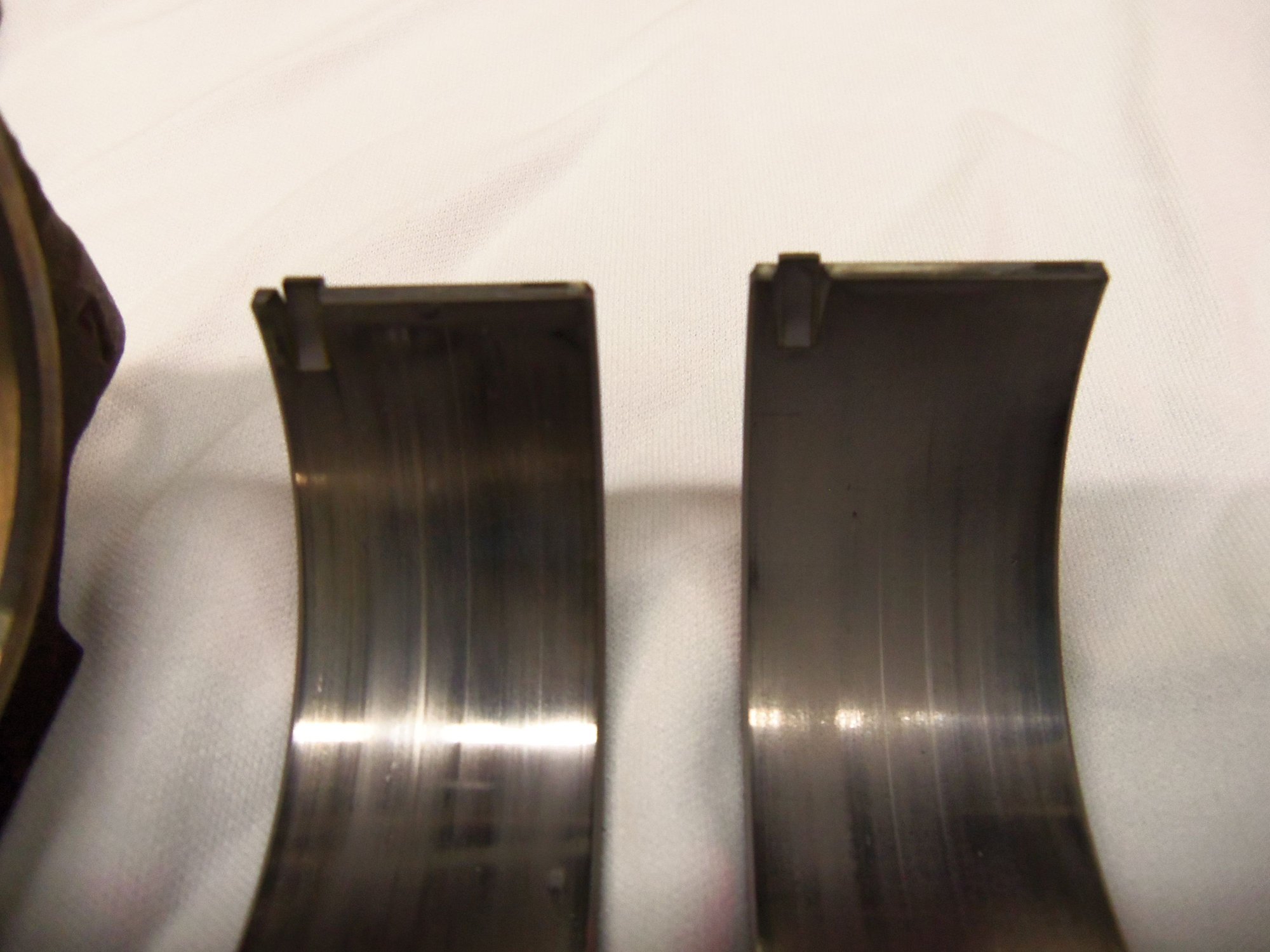
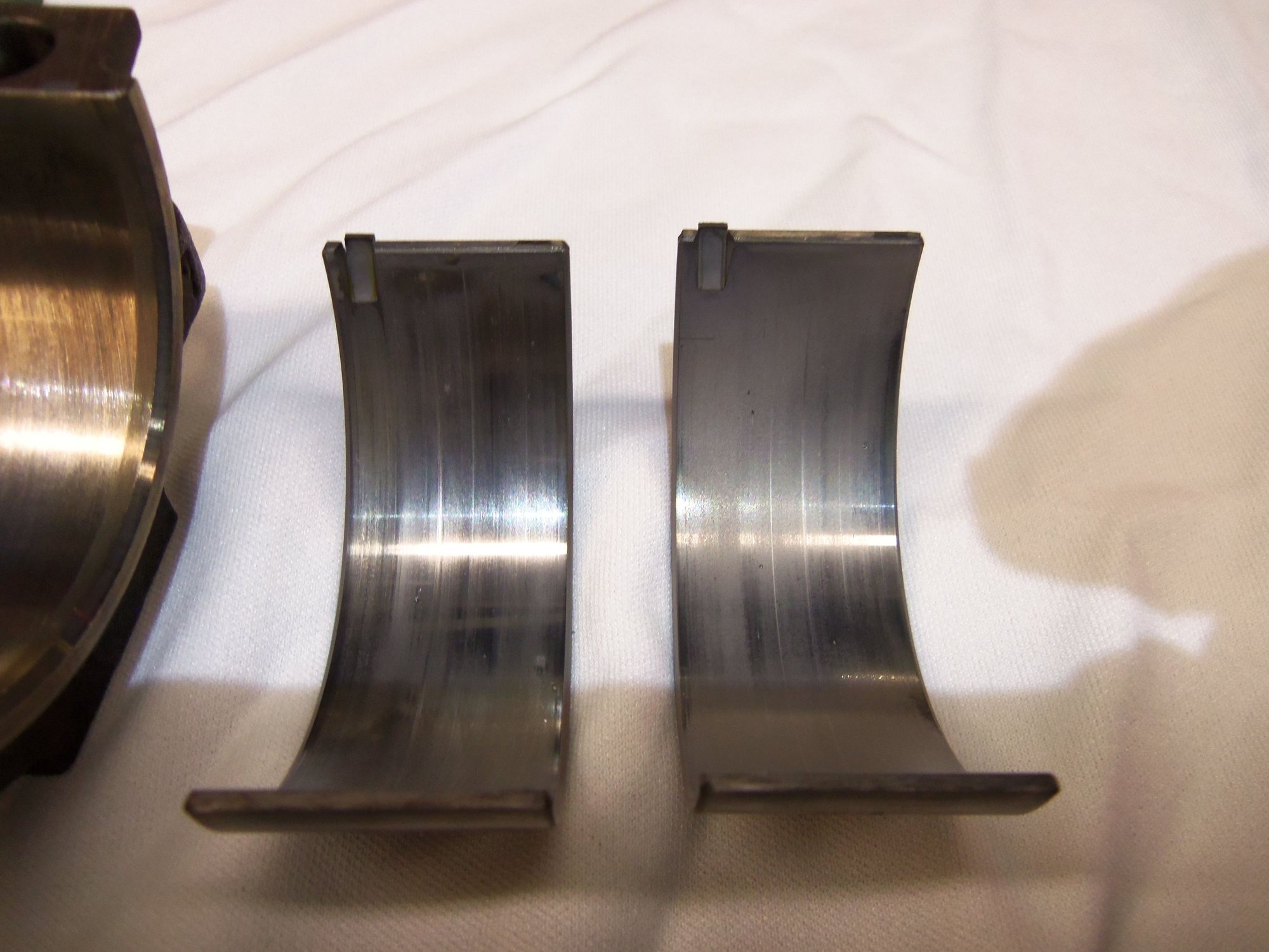
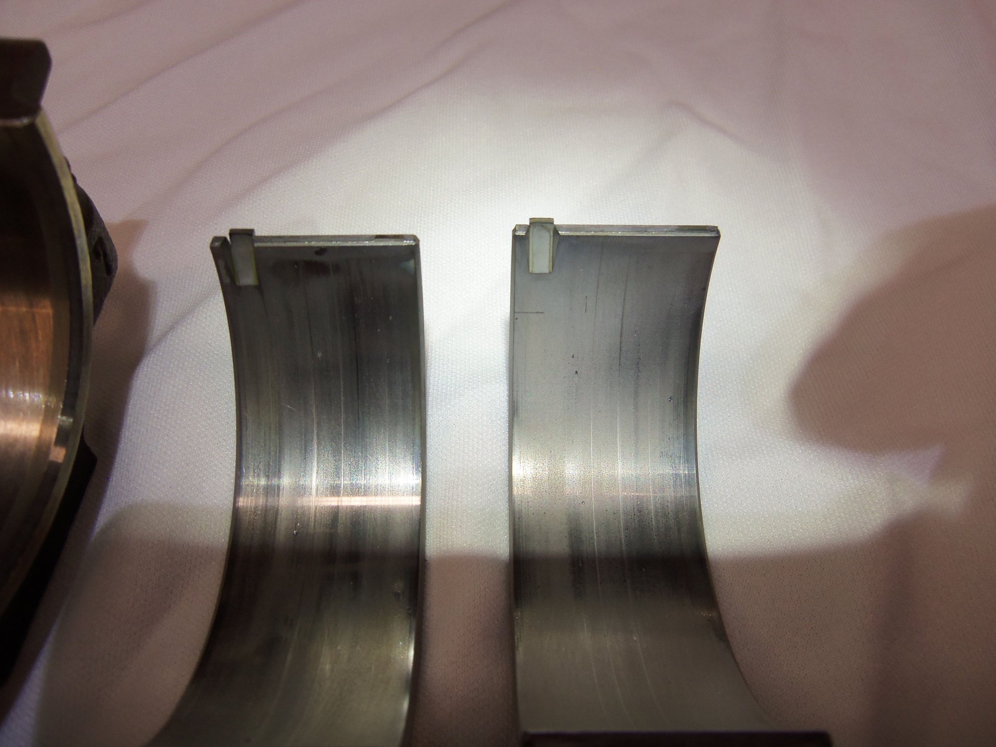
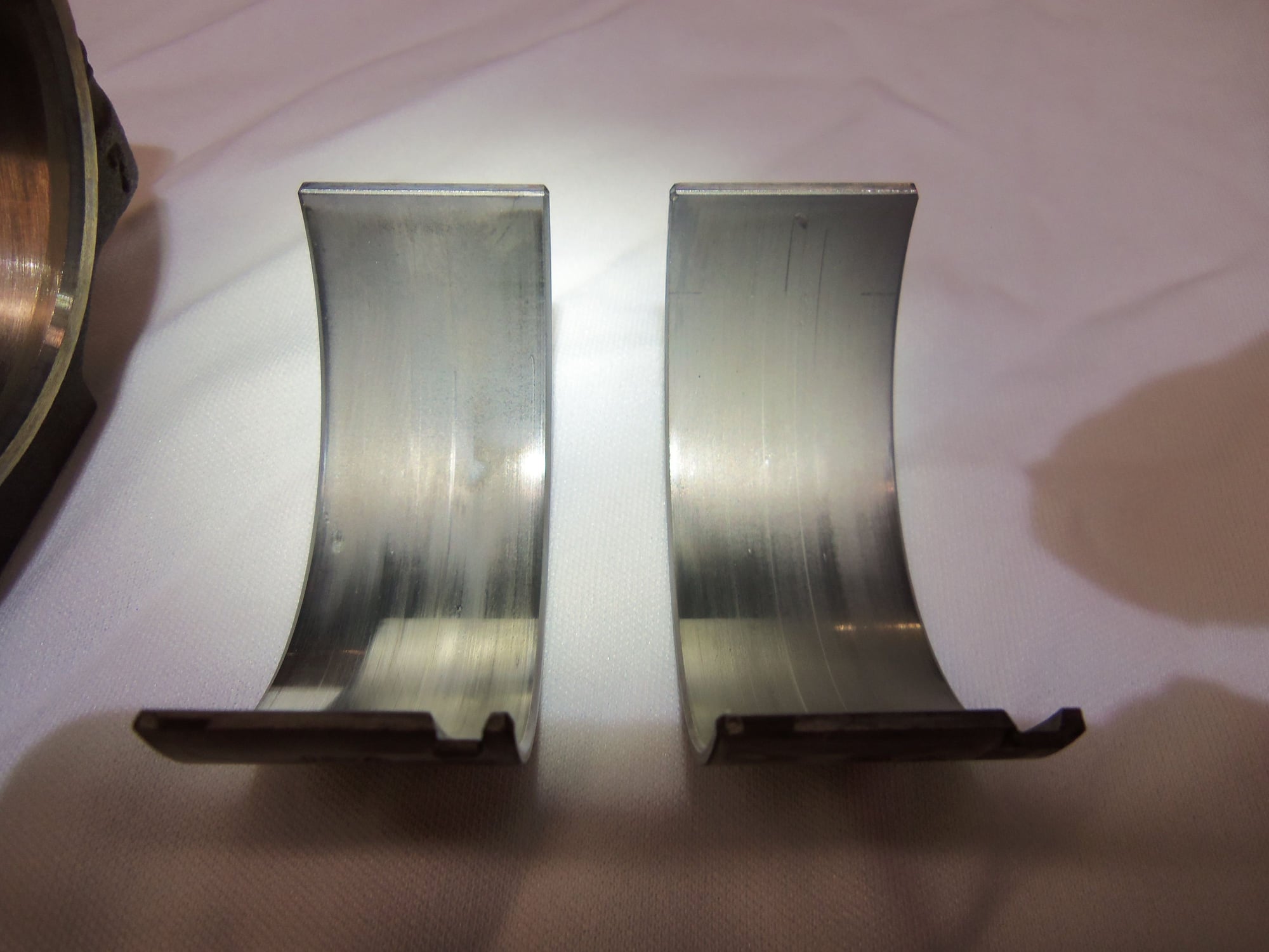
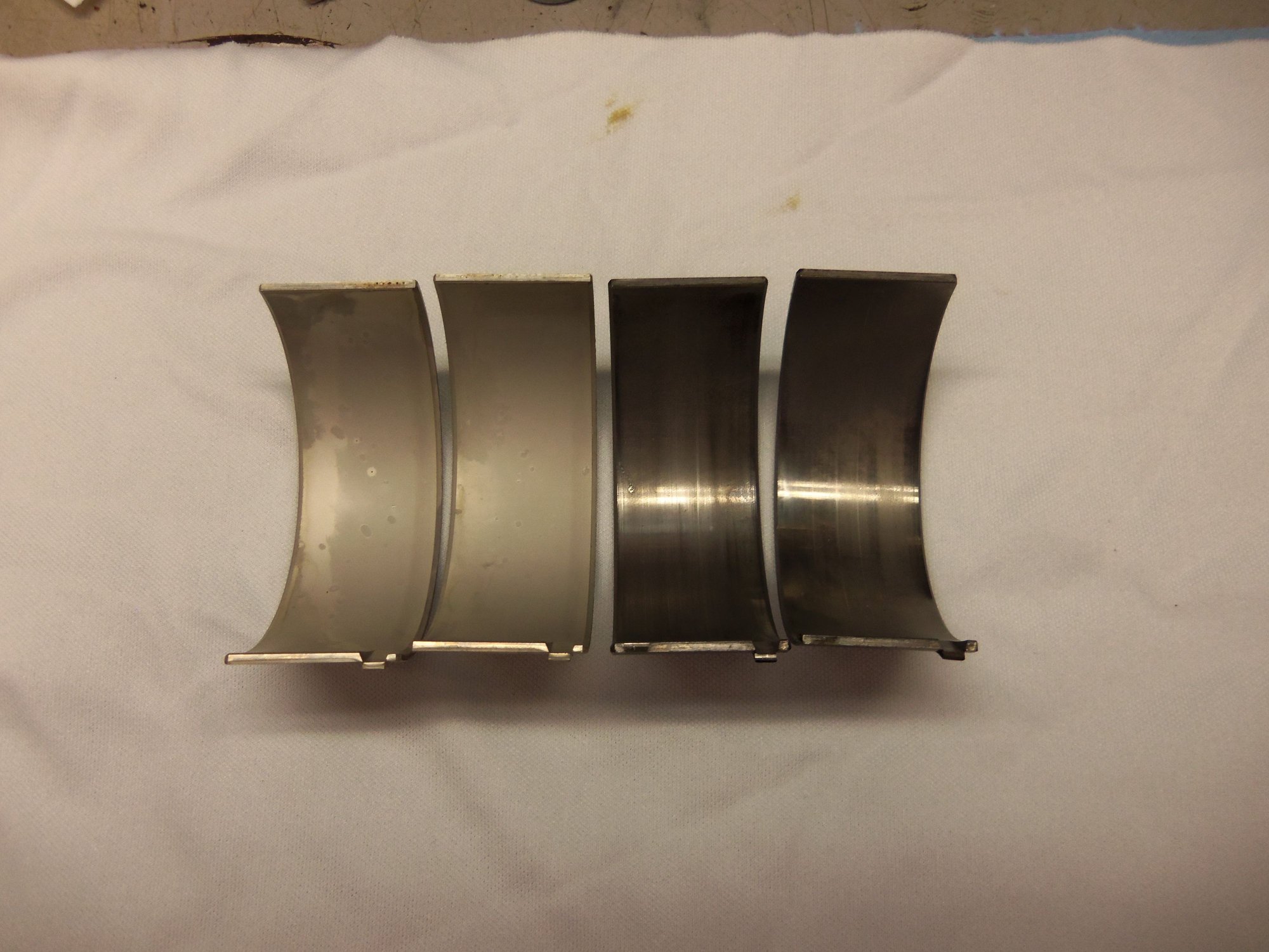
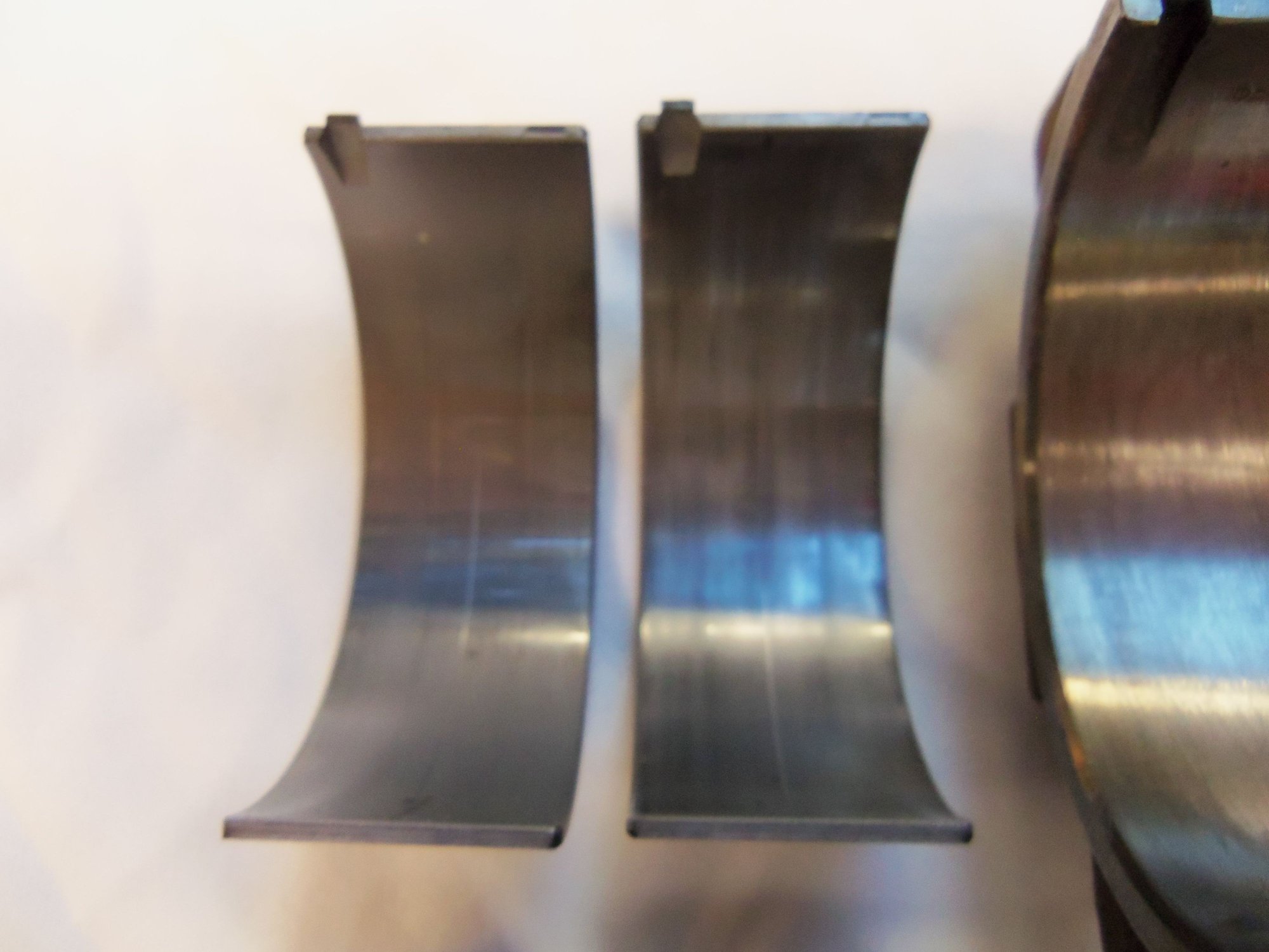
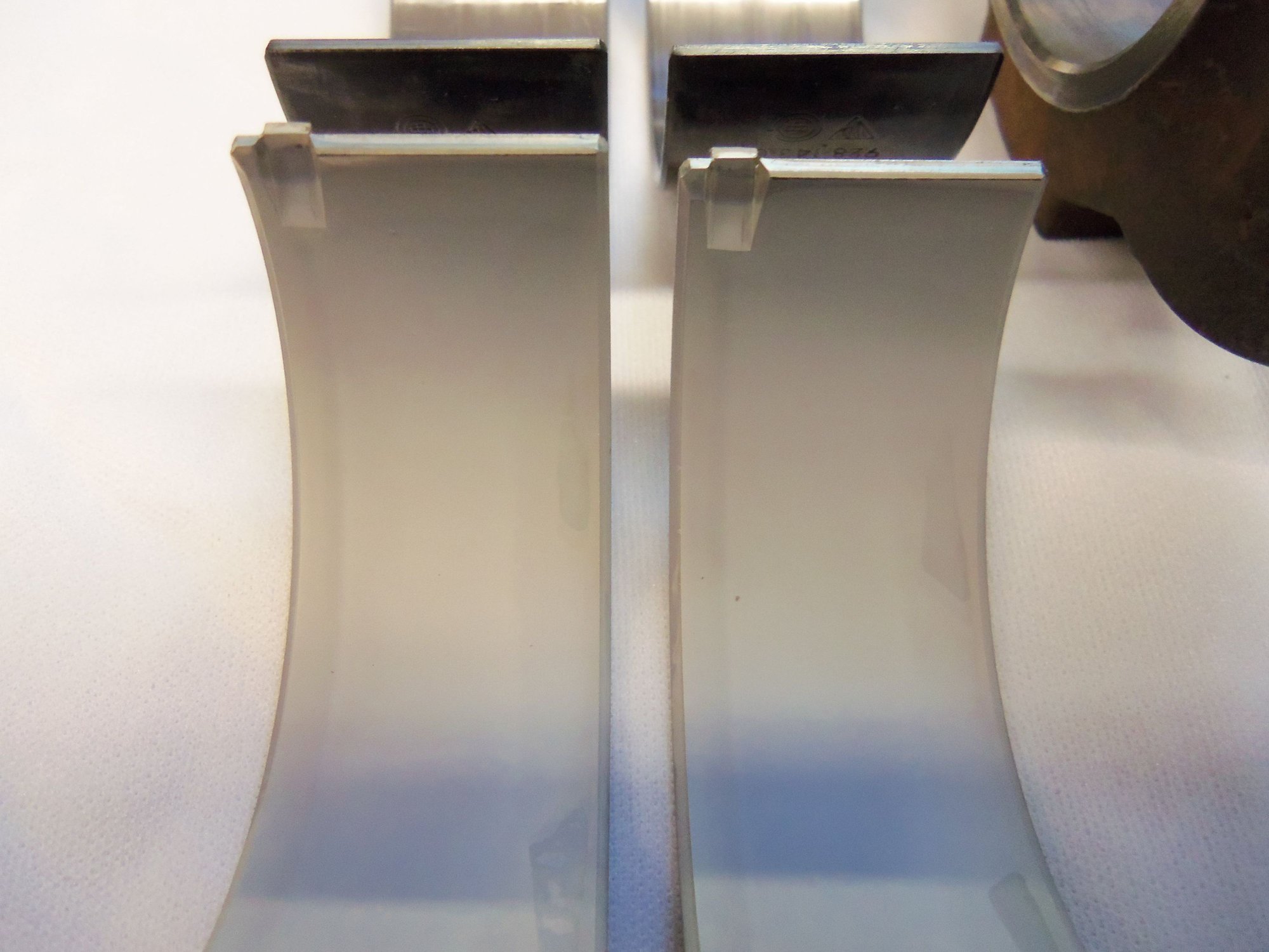
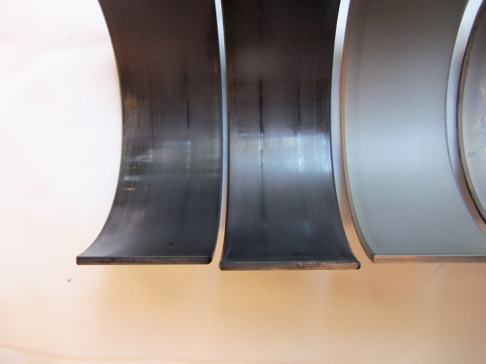
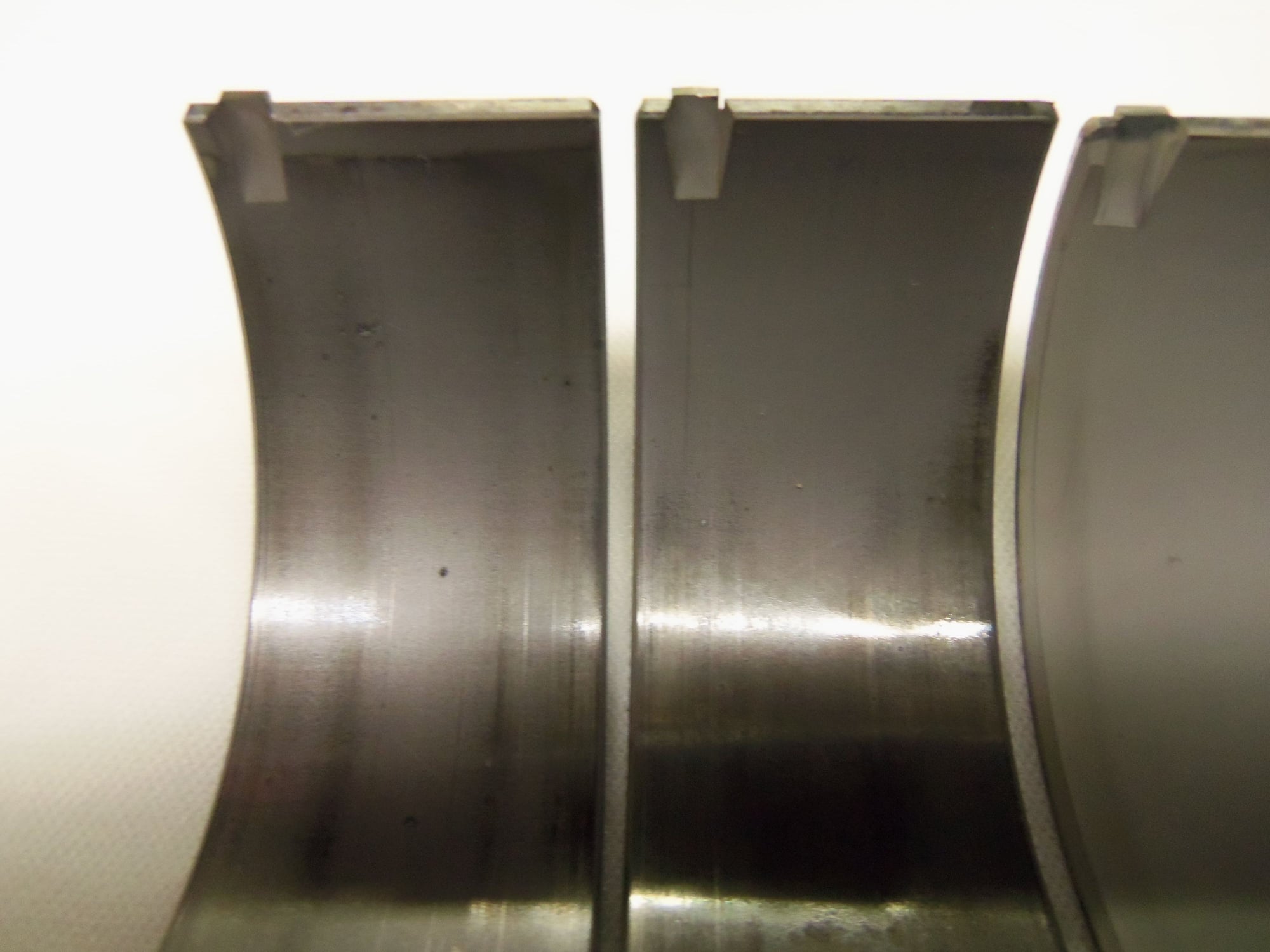
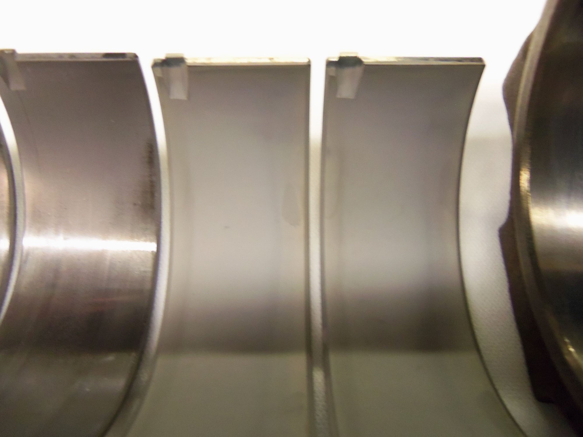
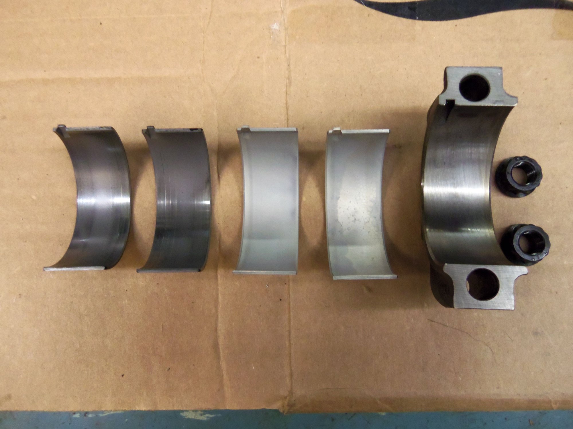
Note: on the photos of the rod bearing shells, I took several in differing light to try to get the best veiws of the bearing surfaces. I VERY much want more experienced eyes to look at these. I believe they are good to run again, based more on clearance, and then on appearance.
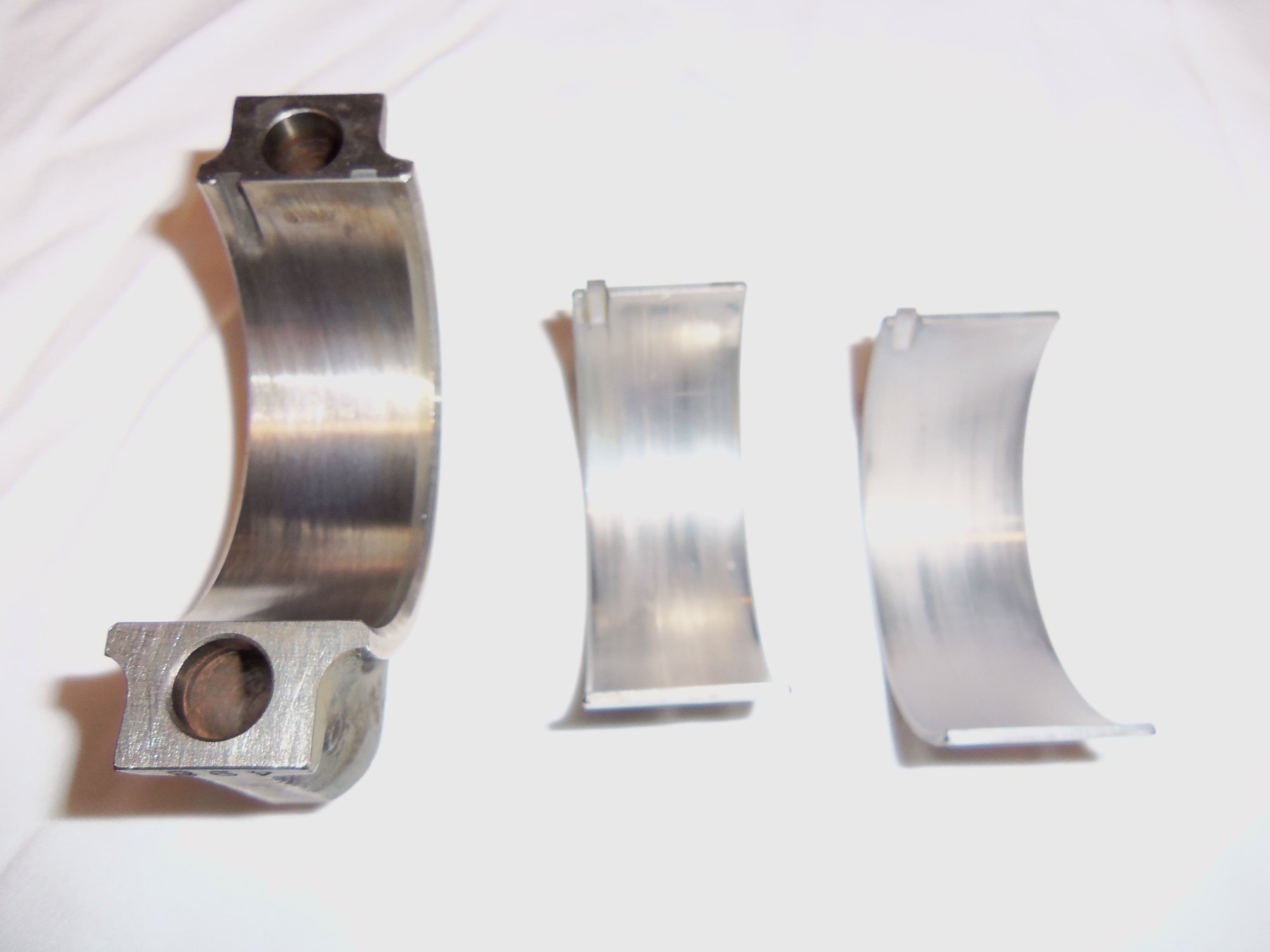
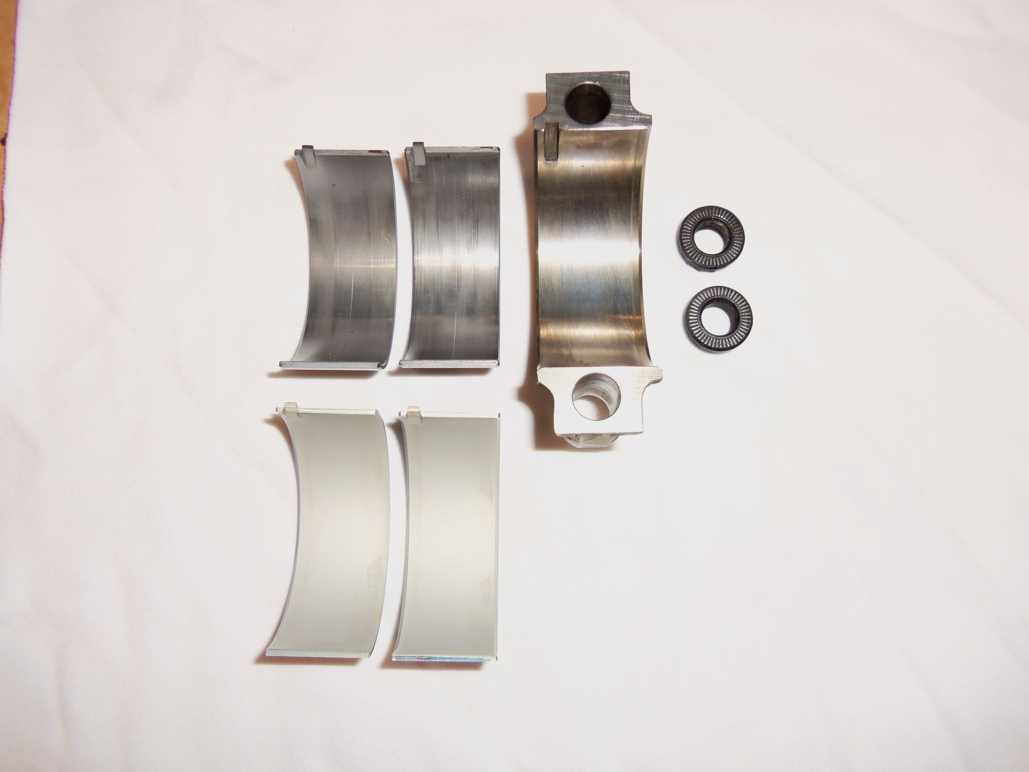
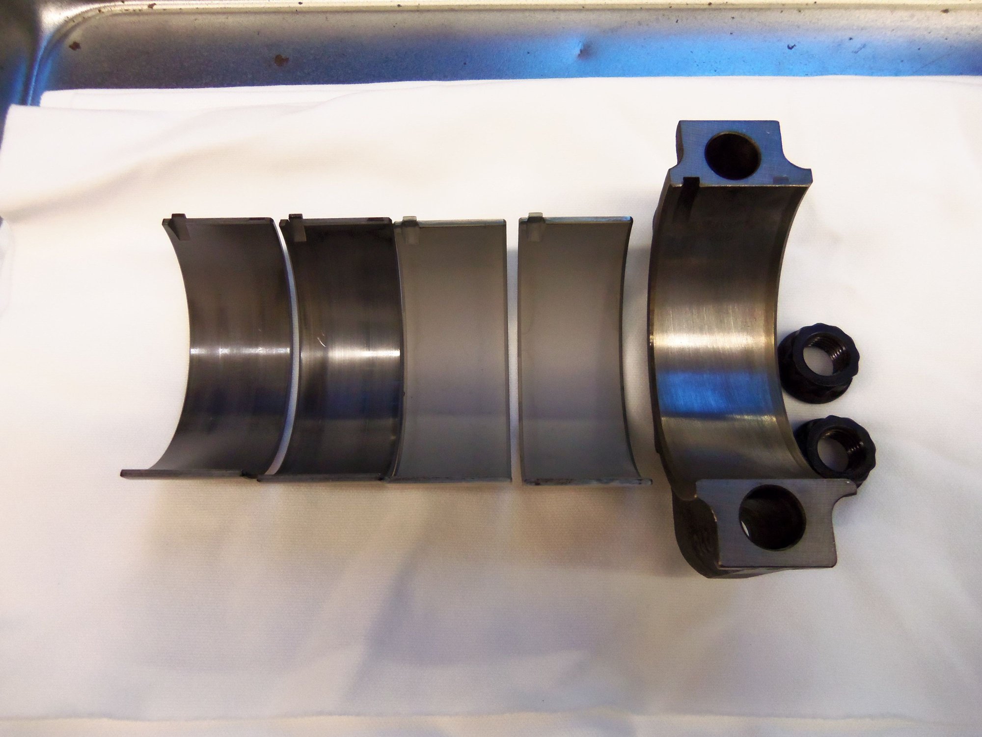
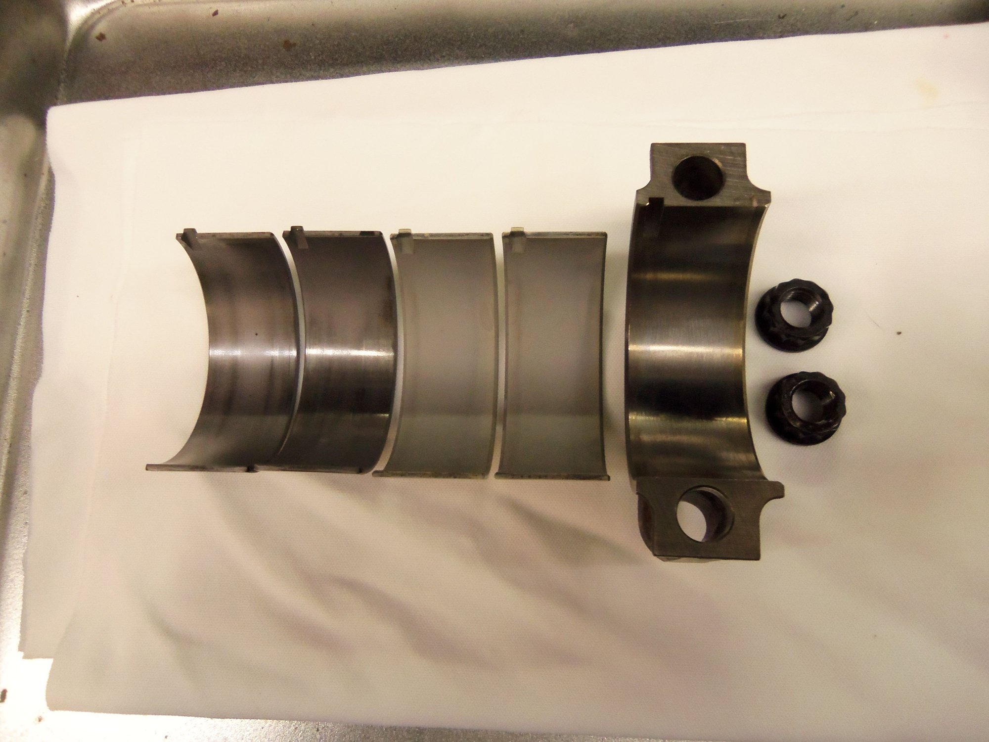
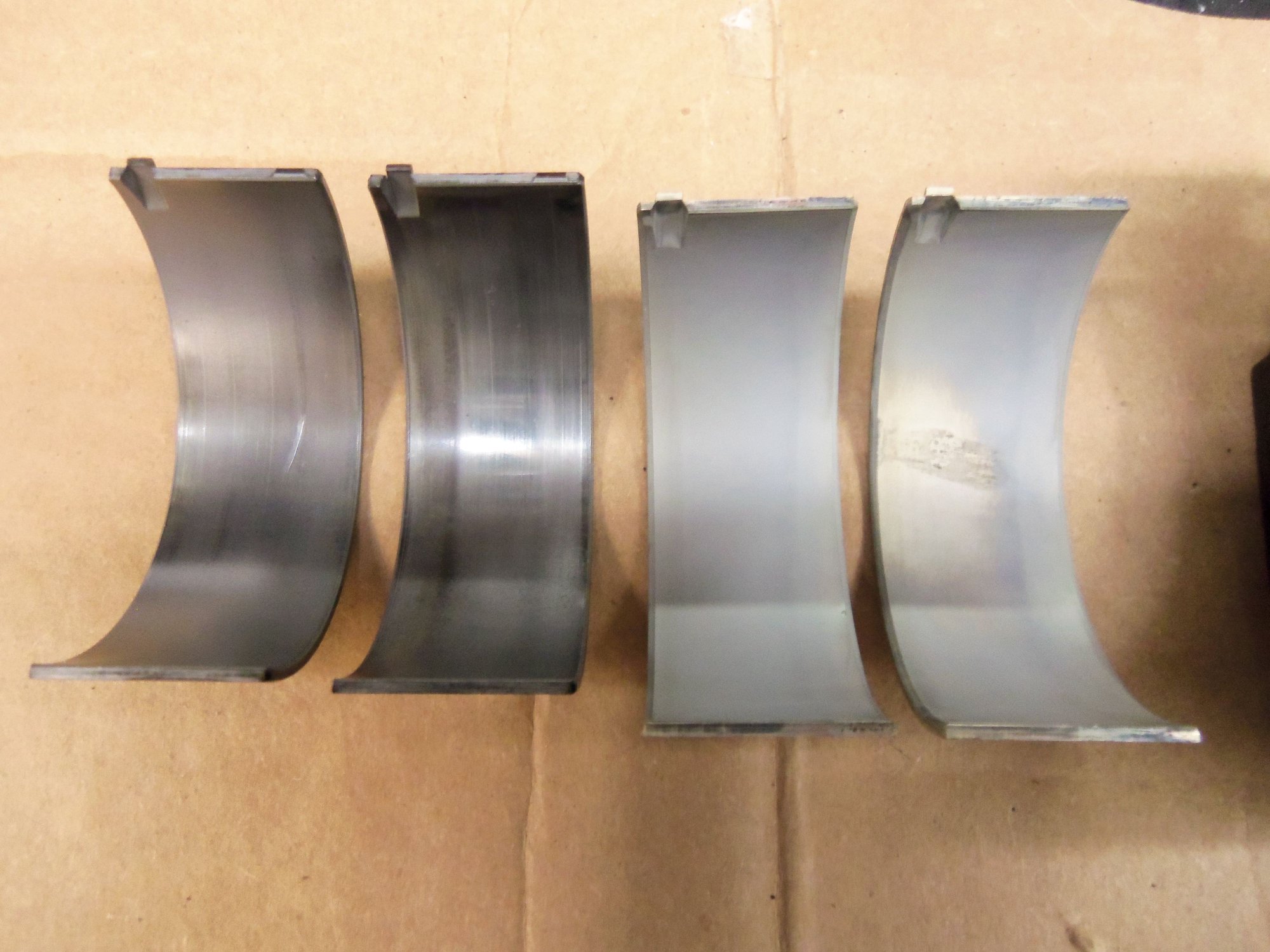
Rod cap, lower shell, upper shell.
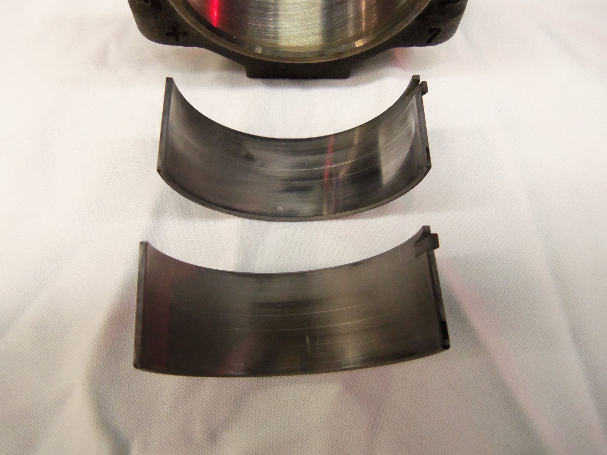
Lower shell is above, upper shell is below.
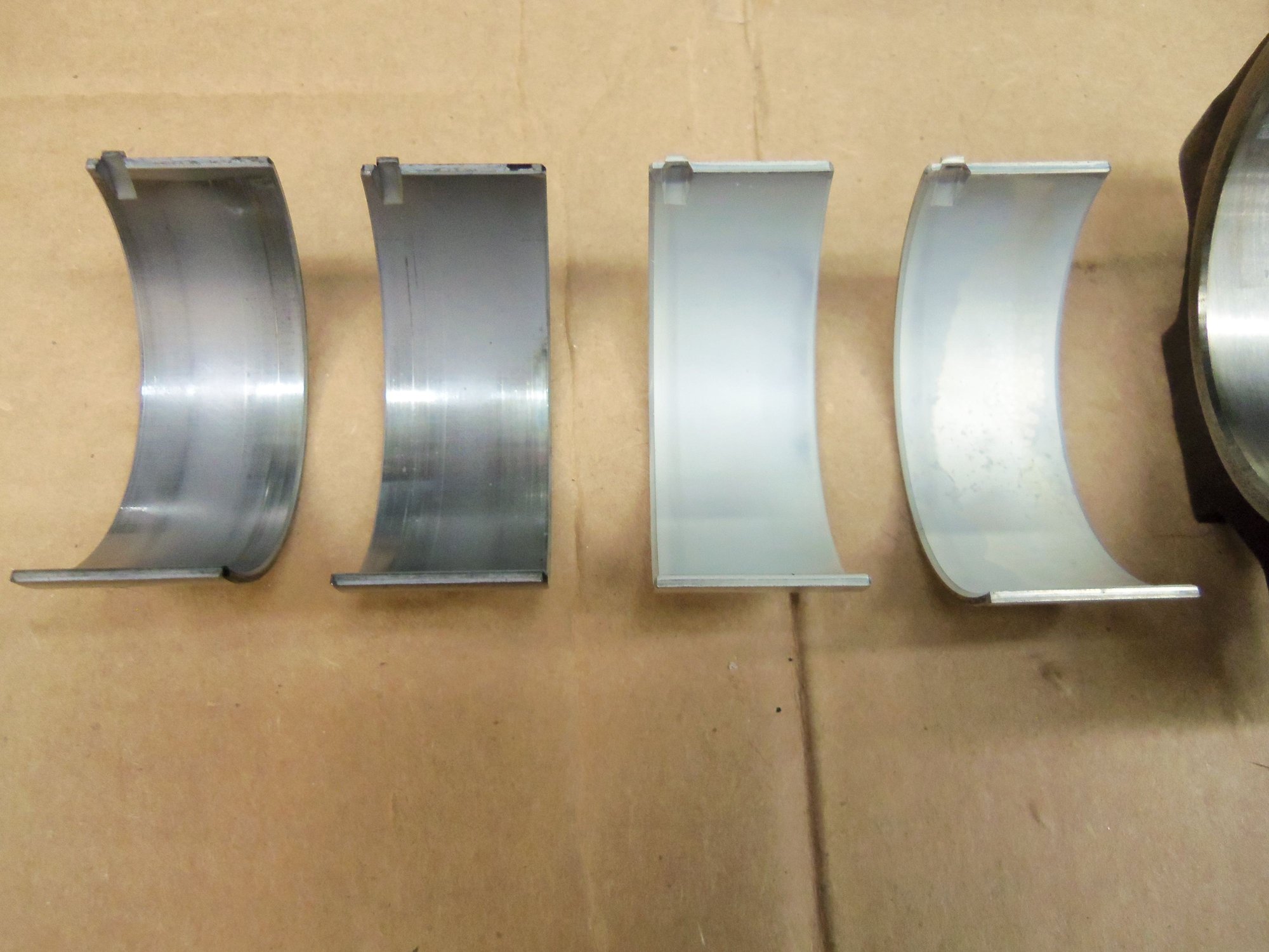
Lower shell is to the left, upper shell is to the right.
Lower shell is to the left, upper shell is to the right.
Lower shell is to the left, upper shell is to the right.
Lower shell is to the left, upper shell is to the right. Shells have been turned around to see the other side surface.
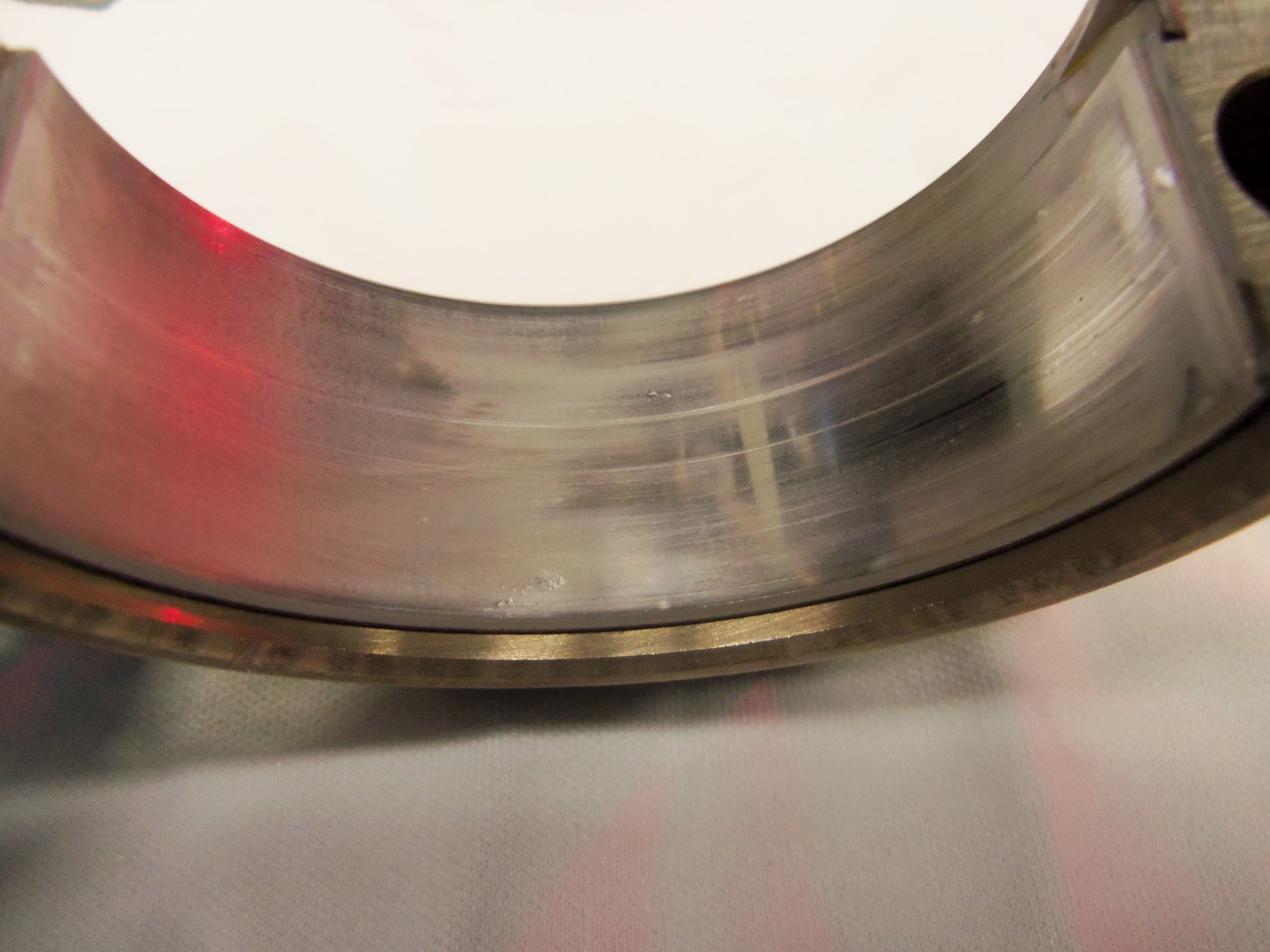
Little something at the lower middle of the lower shell.
Better view of the little something in the lower middle of the lower shell.
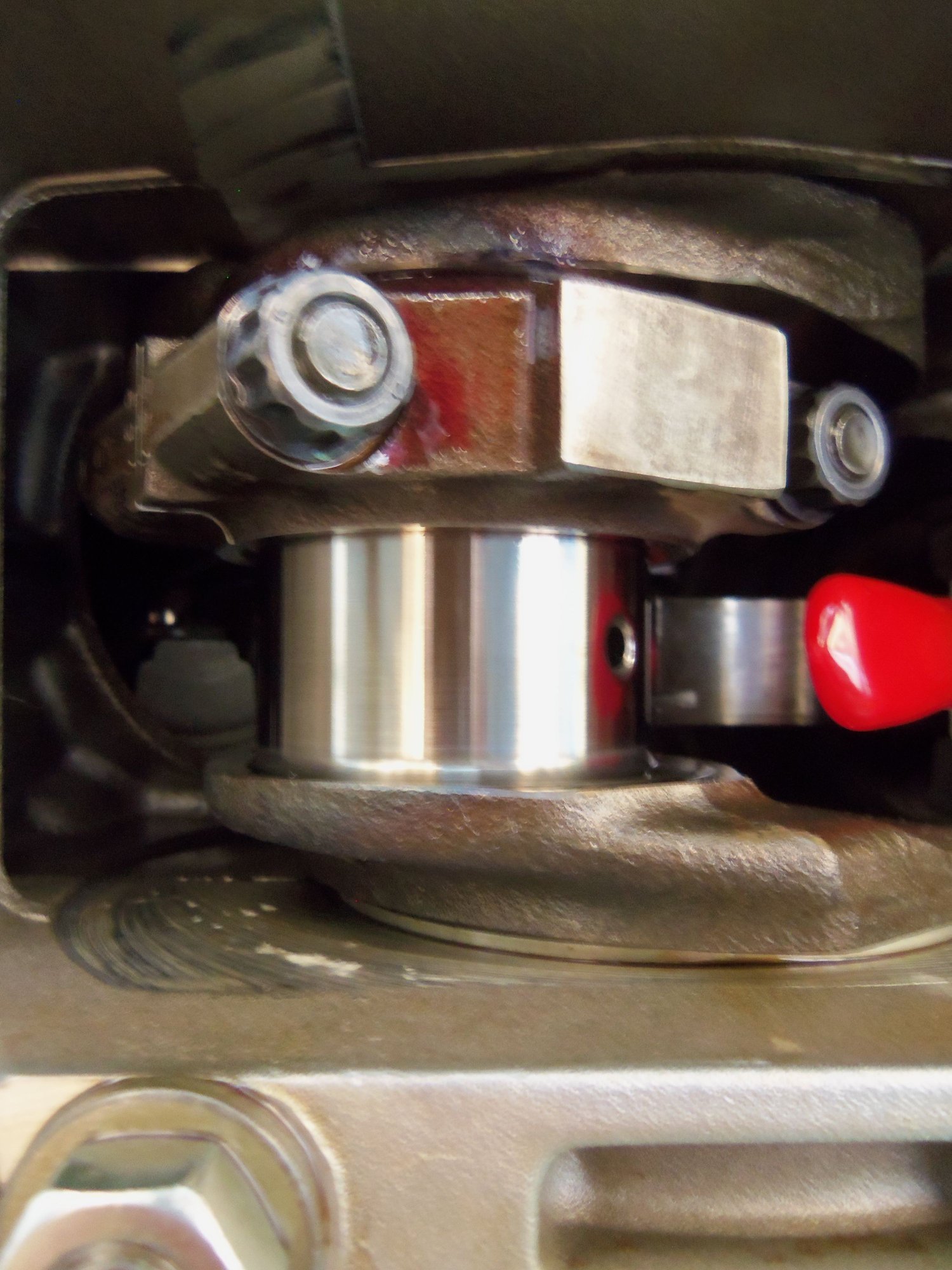
Pristine rod journal.
Cleaned, lubed, and back together with new nuts.
I'd put those bearings back in and tighten the rod nuts up snug, using the old rod nuts, for now.
Continue your inspection, starting with #2 and #6.
I've got a feeling that by the time you see all of the rod bearings, you will decide to install an entire set.....requiring another set of rod nuts (if you use the new nuts, now.)
Rod bearings are a consumable....much like gaskets. 160,000 miles....they have done their job.
The current Glyco rod bearings that we have been getting have had good clearance....not the same issues that occurred a couple of years ago. A set of Glyco rod bearings will be a "rounding error" by the time you are done with your 928.
Hello Greg, thanks for looking at the pictures.
So I understand properly, The Glyco bearings are now a good choice? No more issues of inconsistencies in thickness?
I have a quote out for a full set now.
Silly question: If I am replacing the rod bearings, do I still need to check clearances on the old ones? Or, just do a visual. Then install the new bearings and check clearances on them.
Thanks!
(To all others who have posted, I will reply soon. I am sick right now and barely functioning.)
If your bearings continue to look like these two samples, you could (in theory) re-use them. Your bearings do have small scratches from dirt and the super soft first layer is largely gone....but if I was in the middle of Oklahoma during the depression, I would certainly re-use them.
As I've tried (many tines) to make people aware of, there were originally 3 distinct different rod bearing sizes to allow Porsche to select the proper rod bearings for each crankshaft journal.
For quite some time, Glyco was providing very "tight" clearance rod bearings....as tight or tighter than any of the original Porsche bearings, which caused engines to have inadequate oil clearance and thus failures.
I'm certainly not invloved with any engineering decisions made by Glyco, but I assume that they figured that all crankshafts would wear some....just over time and use....and since they were supplying bearings for used crankshafts, they probably thought that they should "croud" the tighter end of the "standard" size.
Unfortunately, 928 crankshafts are very hard on the surface and do not seem to wear, unless something very catastrophic occurs.
The current bearings that Glyco is providing have been on the,"loose" end of the specifications.
Bearing clearance should always be checked when changing bearings. I use a bearing micrometer to measure the actual thickness and compare that to the original bearings and/or measure the actual clearance with a bore micrometer and a crankshaft micrometer. I haven't used Plastigage for over 30 years. (Understand that the engines i do are almost always completely apart. Measuring the bore on an installed connecting rod is VERY difficult, so in this case Plastigage should be adequate.)
Checking clearance on bearings that have run for 150,000 is a waste of effort....they obviously worked!
Of course there is the question if the factory rod bearings are exactly the same as the Glyco replacements. (Like the whole question of cam belts being exactly the same....which they are not.) There's no way for me to be absolutely sure....but the two different bearings weigh within hundredths of a gram of each other, so chances are very good that they are very, very similar.
If it was a tractor, you could put those bearing shells back in and use it. As it is, you're going to find worse wear on 2/6, so as long as you are there, just put new shells on. When you get the new bearings, keep the old rod bolts and nuts and definitely do a clearance check. If you want to check for rod big end oval, try a plastigage at the middle of the shell, and try one over by the cap edge. Sometimes you can get interesting results on the eccentricity of the rod big-end.
Those shells look pretty darn good to me as do those plastigage values. I regret not opening my big ends when I had the chance albeit I am confident they were in good nick then and hopefully still now some 10 years on with close to 100k miles under their belt.
Will be interesting to see what the Brains Trust thinks. I could surely do with your new sump gasket that was leaking a bit- not too surprising seeing as how half the bolts or more were loose- urrgh! I tightended the as sensibly as I could - hopefully it will improve the weepage that was not too bad really.
Thanks Fred! These look good, but based upon advice, I am installing a set of new Glyco rod bearings.
I hear you, awhile ago, I tightened the oil pan bolts on the Red Witch. They were pretty much finger tight.
Originally Posted by G.P.
Thank you for a detailed post with pictures.
I can see myself doing this in the future, and referring back to this thread.
Thanks G.P.! Good luck to you! This seems daunting, but if you take it step by step, you will be fine.
Just rob a bank first...
If your bearings continue to look like these two samples, you could (in theory) re-use them. Your bearings do have small scratches from dirt and the super soft first layer is largely gone....but if I was in the middle of Oklahoma during the depression, I would certainly re-use them.
As I've tried (many tines) to make people aware of, there were originally 3 distinct different rod bearing sizes to allow Porsche to select the proper rod bearings for each crankshaft journal.
For quite some time, Glyco was providing very "tight" clearance rod bearings....as tight or tighter than any of the original Porsche bearings, which caused engines to have inadequate oil clearance and thus failures.
I'm certainly not invloved with any engineering decisions made by Glyco, but I assume that they figured that all crankshafts would wear some....just over time and use....and since they were supplying bearings for used crankshafts, they probably thought that they should "croud" the tighter end of the "standard" size.
Unfortunately, 928 crankshafts are very hard on the surface and do not seem to wear, unless something very catastrophic occurs.
The current bearings that Glyco is providing have been on the,"loose" end of the specifications.
Bearing clearance should always be checked when changing bearings. I use a bearing micrometer to measure the actual thickness and compare that to the original bearings and/or measure the actual clearance with a bore micrometer and a crankshaft micrometer. I haven't used Plastigage for over 30 years. (Understand that the engines i do are almost always completely apart. Measuring the bore on an installed connecting rod is VERY difficult, so in this case Plastigage should be adequate.)
Checking clearance on bearings that have run for 150,000 is a waste of effort....they obviously worked!
Of course there is the question if the factory rod bearings are exactly the same as the Glyco replacements. (Like the whole question of cam belts being exactly the same....which they are not.) There's no way for me to be absolutely sure....but the two different bearings weigh within hundredths of a gram of each other, so chances are very good that they are very, very similar.
Thanks, Greg! I appreciate the advice and clarification. When I inspected the bearing shells from #1 rod, I saw not color markings of any kind. From what I understand, that is normal, as the oily environment eats away the paint pretty quickly. I have no way of knowing what 'group' of rod bearings were originally fitted.
I understand what you are saying about the scratches in the bearing shells and the mostly worn away soft outer layer. Those bearings definitely did their job.
I am taking your advice and fitting a new set of Glyco connecting rod bearings. They have been ordered. Since this is pretty much meatball surgery with me on my back and the engine still installed, I will check clearances with the new bearings with plastigage, and go from there. I am going to hope I see no more than 0.05mm of clearance.
I understand that checking clearance on used bearings is a waste of time. However, I would have liked to know if the bearings were excessively worn.
Originally Posted by docmirror
If it was a tractor, you could put those bearing shells back in and use it. As it is, you're going to find worse wear on 2/6, so as long as you are there, just put new shells on. When you get the new bearings, keep the old rod bolts and nuts and definitely do a clearance check. If you want to check for rod big end oval, try a plastigage at the middle of the shell, and try one over by the cap edge. Sometimes you can get interesting results on the eccentricity of the rod big-end.
Doc, that is something I had not considered. I know that rod bearings are a tad egg shaped, so you get the proper crush at the parting lines. However, I am not sure if I can pull off measuring the clearance at both points. Due to the angle of the rod in the cylinder, and gravity, I could not get the plastigage to stay dead in the center of the lower bearing shell. It ended up near the low side parting line.
I am not sure if I can use something to 'stick' the plastigage in place. Spit? I know the rod journal and bearings need to be clean and dry.
You have given me something to think about. Thanks!
I am fitting new Glyco bearing shells. I am constantly b*itching to myself that I have spent WAY too much money on the Red Witch. But, this falls in the category of 'stupid not to do while in there.' A new set of bearings is on order.
For the moment, I am leaving the rods and bearings alone. I will pick back up when the bearing shells come in. For now, I will continue on with cleaning the steering rack, cross member, etc...all parts that came off.
I have several used MM mounting pieces from 928 Intl that are in MUCH better condition than what I have. That, and actually install the new motor mounts.
I am going to find out if I can remove the old bellows boots from the steering rack over the outer tie rod ends. Might be able to do it. If so, might be able to reinstall the new ones in the same manner.
We will find out...
Thanks for the advice! I am very much making this up as I go, and the help from the Rennlist 928 community has been invaluable!!!
Thanks, Greg! I appreciate the advice and clarification. When I inspected the bearing shells from #1 rod, I saw not color markings of any kind. From what I understand, that is normal, as the oily environment eats away the paint pretty quickly. I have no way of knowing what 'group' of rod bearings were originally fitted.
I understand what you are saying about the scratches in the bearing shells and the mostly worn away soft outer layer. Those bearings definitely did their job.
I am taking your advice and fitting a new set of Glyco connecting rod bearings. They have been ordered. Since this is pretty much meatball surgery with me on my back and the engine still installed, I will check clearances with the new bearings with plastigage, and go from there. I am going to hope I see no more than 0.05mm of clearance.
I understand that checking clearance on used bearings is a waste of time. However, I would have liked to know if the bearings were excessively worn.
Doc, that is something I had not considered. I know that rod bearings are a tad egg shaped, so you get the proper crush at the parting lines. However, I am not sure if I can pull off measuring the clearance at both points. Due to the angle of the rod in the cylinder, and gravity, I could not get the plastigage to stay dead in the center of the lower bearing shell. It ended up near the low side parting line.
I am not sure if I can use something to 'stick' the plastigage in place. Spit? I know the rod journal and bearings need to be clean and dry.
You have given me something to think about. Thanks!
I am fitting new Glyco bearing shells. I am constantly b*itching to myself that I have spent WAY too much money on the Red Witch. But, this falls in the category of 'stupid not to do while in there.' A new set of bearings is on order.
For the moment, I am leaving the rods and bearings alone. I will pick back up when the bearing shells come in. For now, I will continue on with cleaning the steering rack, cross member, etc...all parts that came off.
I have several used MM mounting pieces from 928 Intl that are in MUCH better condition than what I have. That, and actually install the new motor mounts.
I am going to find out if I can remove the old bellows boots from the steering rack over the outer tie rod ends. Might be able to do it. If so, might be able to reinstall the new ones in the same manner.
We will find out...
Thanks for the advice! I am very much making this up as I go, and the help from the Rennlist 928 community has been invaluable!!!
You don't need to worry about the clearance near the parting line of the bearing.
This dimension changes from one rod bearing design to the next. Generally, the higher the anticipated rpm use will be, the higher the clearance will be as you get towards the parting line. The stock Porsche bearings stay pretty much the same thickness until you get very close to the parting line....you can see this on the used bearings. You get into a Clevite 77 bearing designed for use in Nascar engines, and the clearance at the parting line starts increasing 1/2" or more from the parting line.
Doc, that is something I had not considered. I know that rod bearings are a tad egg shaped, so you get the proper crush at the parting lines. However, I am not sure if I can pull off measuring the clearance at both points. Due to the angle of the rod in the cylinder, and gravity, I could not get the plastigage to stay dead in the center of the lower bearing shell. It ended up near the low side parting line.
I am not sure if I can use something to 'stick' the plastigage in place. Spit? I know the rod journal and bearings need to be clean and dry.
You have given me something to think about. Thanks!
You won't need the clearance measurement at the edge or parting line of the bearing shell, but it will tell you something about how much oval the big rod end has. The reciprocating forces on the rod tend to stretch them in the length plane. A fairly common shop practice with old engines is to take a very small shave off the rod cap mating face and then 'resize' the hole to take out the eccentricity caused by the elongation. Of course, you won't have your rods out, so this is academic but it would be interesting to know how much stretch you have in the big end of the rod.
As for getting the plastigage to stick over there, I've used a tiny dab of grease. Not a dollop, just use a small screwdriver, get a tiny bit on the tip, and touch it to the bearing shell near the parting face then place the strip of plastigage(I've used tweezers before) on the grease spot dry, and you can usually get it up on the journal if you are careful.
You don't need to worry about the clearance near the parting line of the bearing.
This dimension changes from one rod bearing design to the next. Generally, the higher the anticipated rpm use will be, the higher the clearance will be as you get towards the parting line. The stock Porsche bearings stay pretty much the same thickness until you get very close to the parting line....you can see this on the used bearings. You get into a Clevite 77 bearing designed for use in Nascar engines, and the clearance at the parting line starts increasing 1/2" or more from the parting line.
Makes sense. Thanks!
Originally Posted by docmirror
You won't need the clearance measurement at the edge or parting line of the bearing shell, but it will tell you something about how much oval the big rod end has. The reciprocating forces on the rod tend to stretch them in the length plane. A fairly common shop practice with old engines is to take a very small shave off the rod cap mating face and then 'resize' the hole to take out the eccentricity caused by the elongation. Of course, you won't have your rods out, so this is academic but it would be interesting to know how much stretch you have in the big end of the rod.
As for getting the plastigage to stick over there, I've used a tiny dab of grease. Not a dollop, just use a small screwdriver, get a tiny bit on the tip, and touch it to the bearing shell near the parting face then place the strip of plastigage(I've used tweezers before) on the grease spot dry, and you can usually get it up on the journal if you are careful.
OK, that is familiar to me. The few engines I've overhauled, I've had the rods 'rebuilt'. Part of that was removing the rod bolts, slightly machining the mating faces, installing new rods, then boring and honing the big end to the proper diameter.
I had forgotten about that. Its been awhile.
Very good idea about the dab of grease for the plastigage. Thanks!
Much like the crankshafts, the 928 connecting rods are of high quality and not very stressed in the stock application.
I don't find very many that need to be resized on the big end.
Greg, you were correct, I wasted my time. (refer to post #27)
THE ROD BEARINGS ARE DONE!!!
Tonight, I replaced the rod bearings for cylinders #4 and #8. Those two were the last ones. I had done the rest in the past months.
I am very glad to have finally finished this part of the repair work.
I installed a new set of 16 Glyco 71-3431/4 STD, 928s R Us part number 928 103 143 15G
Listed on the box as Porsche 924/944/968 bearings 85-95
I used 18 new connecting rod nuts 928 103 172 02.
Why 18? Because I am an imbecile, and got out of sequence a couple of times. One time, I grabbed a new nut instead of an old nut for torquing the rod to check clearance. The next, I lost track of which rod I was doing, and loosened a freshly torqued new nut.
I am very pleased to note the following:
-all 8 rod journals on the crankshaft were pristine
-all 16 old rod bearings looked good, meaning they were worn, but not worn out or damaged
-clearance on all 8 sets of new rod bearings was approximately 0.045mm.
Note: I came to the approximate value of 0.045mm because the compressed Plastigauge was larger than 0.051mm and smaller than 0.038mm. Split the middle and you get 0.045mm.
WSM Section 13, page 13-16, gives the tolerance for the clearance of new bearings as 0.020mm to 0.070mm, with the wear limit being 0.100mm.
Mine fall right in the middle of the tolerance. That is a good thing!
I followed this procedure to replace the rod bearing shells:
-turn crankshaft so connecting rod journal is at the bottom
-loosen and remove both connecting rod nuts
(NOTE: crankshaft is ALWAYS turned in the clockwise as facing the engine direction)
-tap the edges of the rod cap with a small brass hammer while pulling down on it
-remove cap when loosened, set cap aside
-put protective caps on rod bolts
-carefully push connecting rod and piston as far up in the bore as it will go
-turn the crank enough that the outboard connecting rod bolt protector will just clear it when pushed outboard
-retrieve upper bearing shell, sometimes they stuck to the rod journal, others I had to pry the shell out via a tiny screwdriver at the bearing tang
-wipe oil off connecting rod journal with a lint free rag
-take a photo of the rod journal and inside of big end of rod
-at the work bench, remove bearing shell from the connecting rod cap
-wipe oil off both bearing shells and inspect surfaces
-clean the rod cap and nuts with brake cleaner, allow to dry
-remove 2 new bearing shells from the plastic packaging, inspect for defects
-take a photo of old bearing shells, new bearing shells, rod cap, and nuts
-install 1 of the new bearing shells in the rod cap
-back under the car, carefully install the other new bearing shell in the connecting rod. This usually entailed some fancy finger dexterity, followed by seating the bearing shell in the tang with a tiny screwdriver
-using a tiny alignment bar with a hooked end, carefully pull the connecting rod and piston down the bore, guiding the bearing onto the rod journal
-clip a short section of green Plastigauge, adhere it to the middle of the bearing shell in the rod cap with a super tiny smear of oil
-remove the rod bolt protective caps
-install the rod cap, ensuring the stamped numbers match up
-install the OLD rod cap nuts, hand tighten
-torque the rod cap nuts in two passes, 25ft/lbs, then 55ft/lbs
-loosen and remove both connecting rod nuts
-tap the edges of the rod cap with a small brass hammer while pulling down on it
-remove cap when loosened, set cap aside
-put protective caps on rod bolts
-measure width of compressed Plastigauge on rod cap bearing shell and on crank journal. Usually, most of the Plastigauge was on the rod journal
-carefully push connecting rod and piston as far up in the bore as it will go
-using a lint free rag and brake cleaner, clean the Plastigauge from the rod cap bearing and the rod journal
-clean fine shavings from old rod cap nuts from surfaces on outer side of rod cap
-lubricate both bearing shells, edges of the rod and cap, and all of the rod journal with Permatex red engine assembly lubricant. Getting to the bearing shell in the connecting rod entailed some fancy finger dexterity.
-using a tiny alignment bar with a hooked end, carefully pull the connecting rod and piston down the bore, guiding the bearing onto the rod journal
-remove the rod bolt protective caps
-retrieve 2 new rod cap nuts from the bag
-install the rod cap, ensuring the stamped numbers match up
-install the NEW rod cap nuts, hand tighten
-torque the rod cap nuts in two passes, 25ft/lbs, then 55ft/lbs
-rotate the crankshaft through a full revolution, checking for binding
Repeat 7 more times...
Photos:
New bearings on the left, old on the right, for cylinder #1.
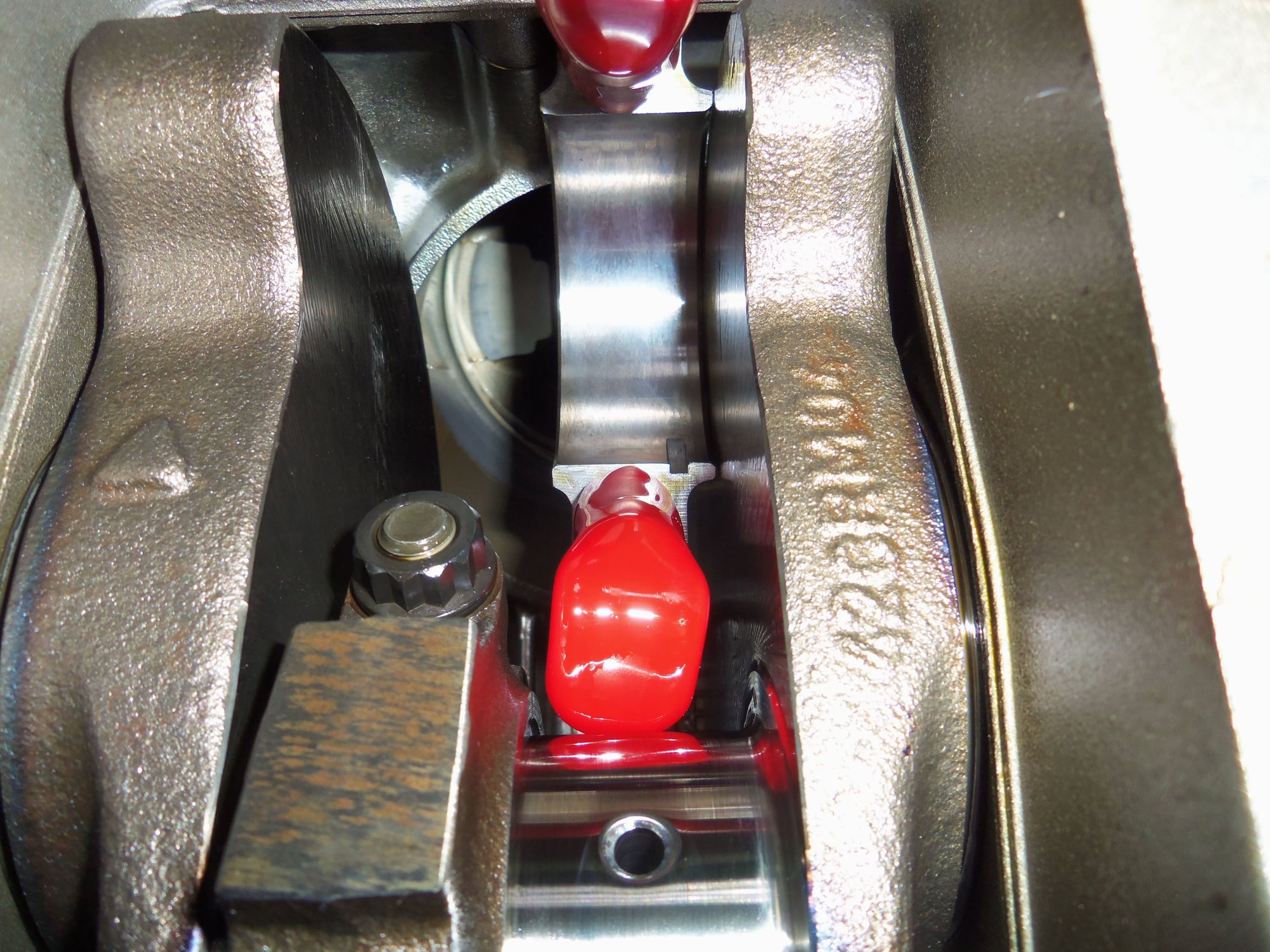
Rod journal #5. Note the red engine assembly lube drooling off the cap for previously done rod #1.
Old bearings on the left, new bearings on the right for cylinder #5.
Old bearings on the left, new bearings on the right, connecting rod cap and nuts for cylinder #2.
Old bearings from cylinder #2.
New bearings for cylinder #2.
#6 rod journal.
Old bearings on the left, new bearings on the right, connecting rod cap and nuts for cylinder #6.
Old bearings from cylinder #6
New bearings for cylinder #6.
#3 rod journal.
Old bearings on the left, new bearings on the right, connecting rod cap and nuts for cylinder #3.
Old bearings from cylinder #3.
New bearings for cylinder #3.
#7 rod journal.
Old bearings on the left, new bearings on the right, connecting rod cap and nuts for cylinder #7.
Old bearings from cylinder #7.
New bearings for cylinder #7.
#4 rod journal.
Big end of #4 connecting rod.
Old bearings on the left, new bearings on the right, connecting rod cap and nuts for cylinder #4.
Old bearings on the left, new bearings on the right for cylinder #4.
#8 rod journal.
Big end of #8 connecting rod.
Old bearings on the left, new bearings on the right, connecting rod cap and nuts for cylinder #8.
Old bearings on the left, new bearings on the right for cylinder #8.
Hopefully, now I have bearing issues covered. The Red Witch has a new oil pump, new rod bearings, new ATI Superdamper, flexplate preload released, Ritech flexplate clamp, and a Greg Brown + Devek oil filler baffle.
That should keep the oil where it belongs and the bearings happy.
Hopefully your diligent efforts will reward you in the long run. The plastiguage readings were interesting in that it suggests your big ends were in great shape. Doubtless prudent to replace them whilst everything was apart and good to know we can purchase a set of bearings that give good clearance results.
Given the numbers you recorded, although somewhat academic, one suspects that those bearings could have gone on to serve for many more thousands of miles. For sure it will be interesting to see how others interpret those numbers.
Hi FredR! Thanks! That has kind of been my guiding philosophy: pain now for better later. At least that is what I tell myself.
Let me clarify something: the Plastigauge readings are for the NEW bearing sets. I only Plastigauged the old bearing set from #1 connecting rod. Subsequent discussion in this thread suggested this was not needed. I moved on to fitting new bearing shells.
I do agree. Based upon what I saw on the bearings, and oil pressure readings, those bearings could have continued on for years. Prudence and WYAIT dictated their replacement.


 04-03-2017, 10:42 PM