

Alternator Cooling Duct Question

Thread Starter
Official Bay Area Patriot
Fuse 24 Assassin
Rennlist Member
Fuse 24 Assassin
Rennlist Member

Joined: Nov 2001
Posts: 31,682
Likes: 125
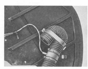
I was looking at a picture in the WSM, which is also linked below from a prior thread showing two duct type hoses for the alternator cooling assembly. The first part is the one that completely rots out on us while the second forms the U-shape we see behind the splash guard. Both of these hoses are clamped to the housing where the HVAC temperature sensor inserts into a coupler.
I am using Ed Scherer's method of repair, but it looks like Ed used only one hose rather than two, and just cut a slit for the temp sensor to be inserted into the coupler. *I THINK*
I have a 6-foot duct at home of some nice oil resistant stuff 2.5" OD. Can't I just slide the coupler in and punch a hole for the sensor to run through? It'd be a shame to cut it into two separate ducts and risk it uncoiling later.
Rennlist Member
Joined: Jun 2005
Posts: 10,567
Likes: 1,027
From: Oman
Andy,
Main thing with that hose is that the air flow path should be in good nick. I doubt it makes any difference where the temperature sensor is located as long as it sees the air flow. I assume the U bend is in effect a snorkel to minimise the chances of sucking water into the alternator in the event you go sub aqua.
Rgds
Fred
Thread Starter
Official Bay Area Patriot
Fuse 24 Assassin
Rennlist Member
Fuse 24 Assassin
Rennlist Member
Joined: Nov 2001
Posts: 31,682
Likes: 125
Hey Fred, sorry I should clarify - I'm not trying to relocate the sensor, but rather trying to find out if I have to cut this hose into two parts. Initially, I was just thinking of leaving it as one whole unit and sliding the HVAC sensor coupler through the hose itself, clamp, punch a hole and insert the sensor.
Rennlist Member
Joined: Jun 2005
Posts: 10,567
Likes: 1,027
From: Oman
Andy,
Your note was perfectly clear- on mine I just inserted the carrier into the end of the hose rather than mess around cutting the hose into two as it were.
Would not appeal to the originality buffs - just saw no point in trying to replicate the stock setup.
Rgds
Fred
Your note was perfectly clear- on mine I just inserted the carrier into the end of the hose rather than mess around cutting the hose into two as it were.
Would not appeal to the originality buffs - just saw no point in trying to replicate the stock setup.
Rgds
Fred
Thread Starter
Official Bay Area Patriot
Fuse 24 Assassin
Rennlist Member
Fuse 24 Assassin
Rennlist Member
Joined: Nov 2001
Posts: 31,682
Likes: 125
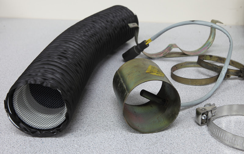
Ah ok. Thanks Fred! I may do the same thing you did along with the screen mod as a 'just in case'. We have been getting critters at my house lately thanks to neighbors leaving food out 
Rennlist Member
Joined: Dec 2002
Posts: 5,283
Likes: 52
From: Australia
Re the front left splash shield and the alternator hose, see how I fixed the hose in place here:-
https://rennlist.com/forums/928-forum...placement.html
Splash shield removal is much easier, and the shield should last a lot longer without the hose load.
jp 83 Euro S AT 57k
https://rennlist.com/forums/928-forum...placement.html
Splash shield removal is much easier, and the shield should last a lot longer without the hose load.
jp 83 Euro S AT 57k
Thread Starter
Official Bay Area Patriot
Fuse 24 Assassin
Rennlist Member
Fuse 24 Assassin
Rennlist Member
Joined: Nov 2001
Posts: 31,682
Likes: 125
I saw some mounting solutions using the fender's crossmember. I was going to attach it at that point. I just need to find out what size bolt or screw to use in order to do it (M6)??
Trending Topics
Addict
Rennlist Member
Rennlist Member
Joined: Jul 2001
Posts: 7,333
Likes: 117
From: Shawnee, KS, USA
I cut it. You can even see the shorter of the two pieces in the fourth photo in the thread.
Note the following excerpt from that post:
Note the following excerpt from that post:
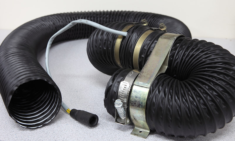
Start reassembling some parts (only the hose used for the "U" part shown here):
... and complete the reassembly. "Screw" the top hose over the bottom one where they join at the sensor mounting tube so if any water spray gets in there, it'll flow over the joint (and down the sensor wire) rather than into it.
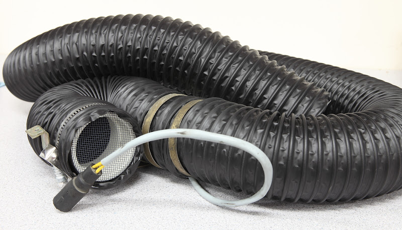
... and complete the reassembly. "Screw" the top hose over the bottom one where they join at the sensor mounting tube so if any water spray gets in there, it'll flow over the joint (and down the sensor wire) rather than into it.

Addict
Lifetime Rennlist
Member
Lifetime Rennlist
Member

Joined: Jun 2000
Posts: 40,491
Likes: 139
From: Insane Diego, California
Good luck installing that hose onto the back side of the splash shield.
it was a real bitch when I had to access my front side marker for a clear lense upgrade.
it was a real bitch when I had to access my front side marker for a clear lense upgrade.

Electron Wrangler
Lifetime Rennlist
Member
Lifetime Rennlist
Member
Joined: Mar 2002
Posts: 13,656
Likes: 616
From: Phoenix AZ
I would recommend everyone to relocate the hose end mounting WYAIT - the back of the splash shield was VERY STUPID idea in the first place. Porsche doesn't always get it right.
Alan
Alan