When you click on links to various merchants on this site and make a purchase, this can result in this site earning a commission. Affiliate programs and affiliations include, but are not limited to, the eBay Partner Network.
Have you checked the ground wire that runs from the rear wheels and above the transmission. It's a combined ground. Took me removing the trans on my car to see that it was the reason my ABS was never working correctly.
Sean , If I understand your post correctly, my ABS sensors do not have dedicated Ground Wires. Based on Roger T's post here, it appears later models may have dedicated grounds per sensor:
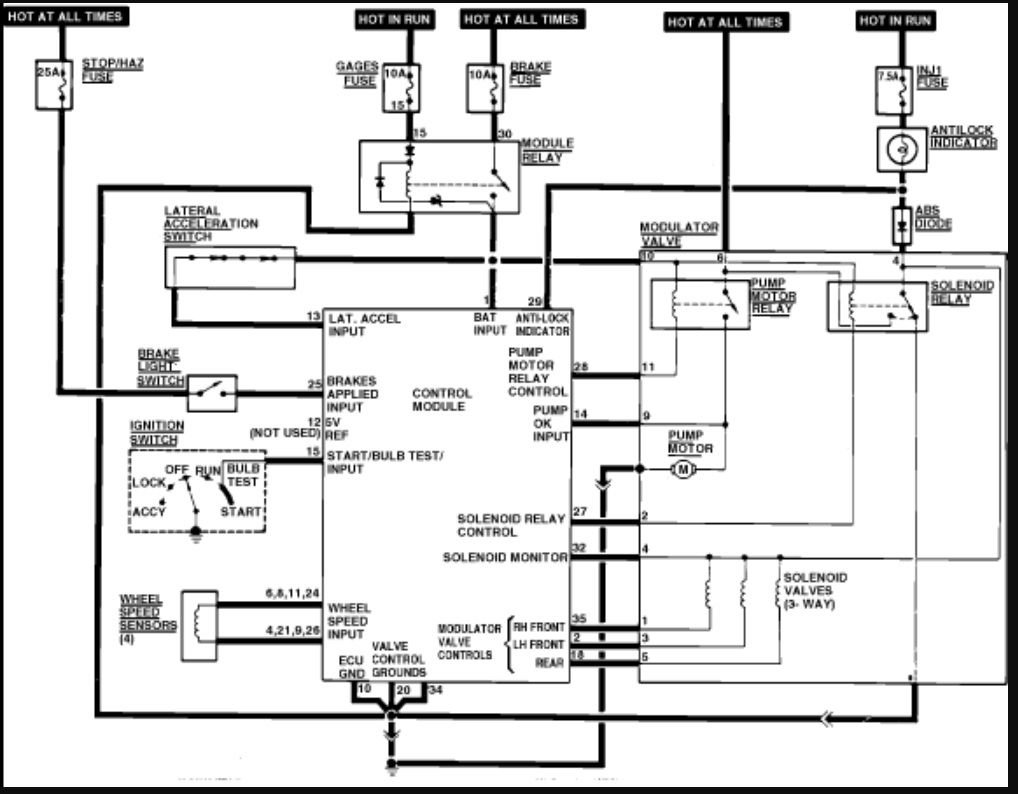
However, my 86 does not utilize those grounds. Below is the ABS schematic I am using to begin the harness troubleshooting. The grounding system is my first target, the grounds have been highlighted in Green. (Note the alerting failure signal has been highlighted in Red, and I am beginning to trace out the power path in Orange.) :
However, I was concerned that since the initiating error/failure seems to be transient, by the time I disconnected the harness form the brain and connected the Bosch KDAS-0003 to the harness, it would show no failure . Is there a way to log the system live so it would throw a flag or error code to show what failure it detected? Or is the last error type stored anywhere in the ABS brain?
My theory is that there is a bad connection somewhere that either shorts out or disconnects for a brief moment during a bump, long enough for the brain to detect it and going into failure mode, but I can't seem to replicate it in the garage.
My 86 was having the exact same symptom - ABS light after a bump, reset perfectly with restart, everything appeared perfect. Appeared. The wire fault was INSIDE the barrel shaped connector, and would measure ok with a ciruit tester, even with wiggling and jouncing. But I opened the barrel connector and could see one of the black wires frayed. Fixing it was difficult - should have replaced it - but it worked out perfectly and the problem immediately stopped happening.
Greg Brown early on mentioned those connectors are common points of failure. Mine have all been replaced with new, modern water tight connectors.
However, I was concerned that since the initiating error/failure seems to be transient, by the time I disconnected the harness form the brain and connected the Bosch KDAS-0003 to the harness, it would show no failure . Is there a way to log the system live so it would throw a flag or error code to show what failure it detected? Or is the last error type stored anywhere in the ABS brain?
My theory is that there is a bad connection somewhere that either shorts out or disconnects for a brief moment during a bump, long enough for the brain to detect it and going into failure mode, but I can't seem to replicate it in the garage.
That's certainly a possibility, however, with your list of things you've replaced, you are determined to fix this problem....and you are running out of pieces to replace.
I don't know how often this problem occurs, but you could always hook up the tester and just drive the car around, testing intermittently, until the problem shows up. (You can monitor the sensors, while driving. (You can switch from sensor to sensor.)
1. Almost guaranteed on any drive over 20 minutes or any drive that involves curbing/gators;
2. My next steps involved doing the ad-hoc version of what you suggest, for example connecting my O-Scope across Term 4&6, then 21&23, then 8&9, then 24&26 then driving around on a bumpy road and watching for signal drop from the related sensors. If sensor signals seem fine,then connecting my DVM or test light across the various power and control paths to watch for blips. The purpose built tool may make that much quicker and more reliable. If I can buy/borrow/steal one, that could be the best path.
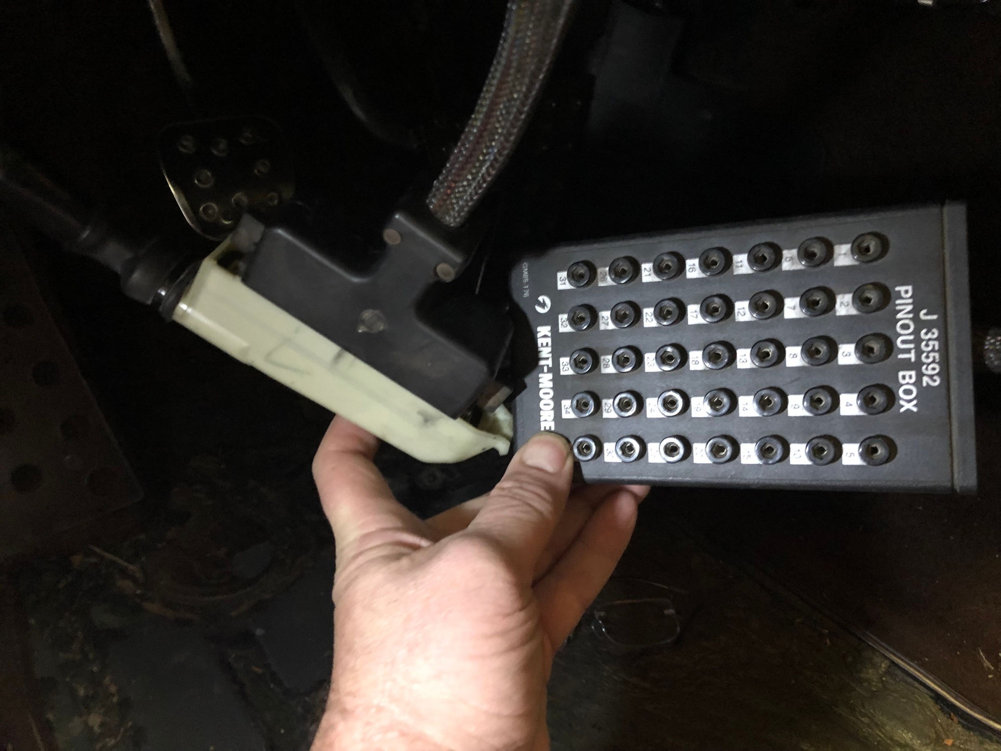
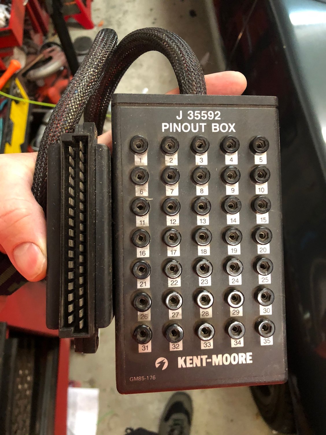
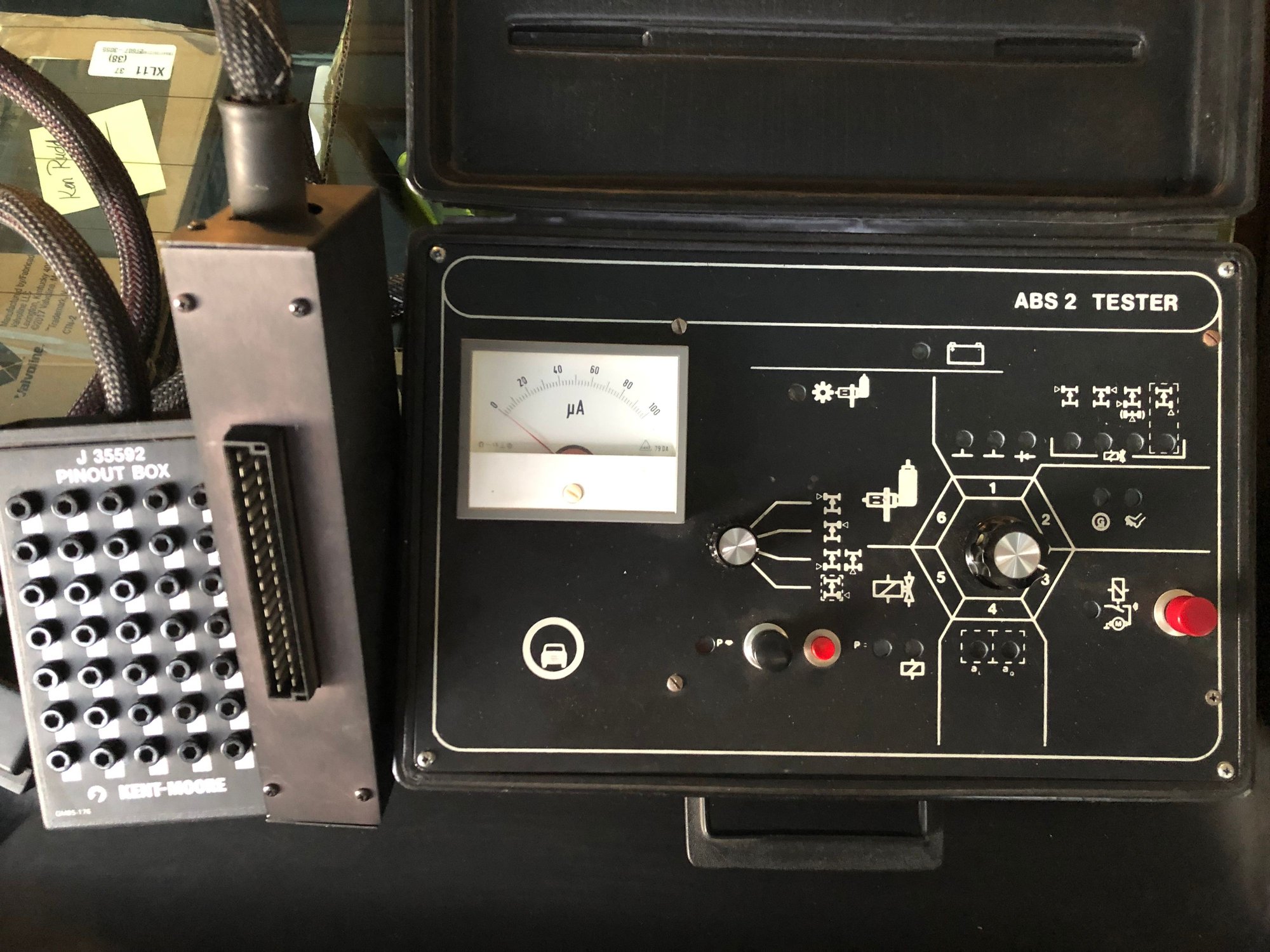
While searching for a full Blown ABS Testing rig, I came across this pinout box for the ABS harness. Not a substitute for a full tester, but does allow connection of standard diagnostic tools to the harness easily.
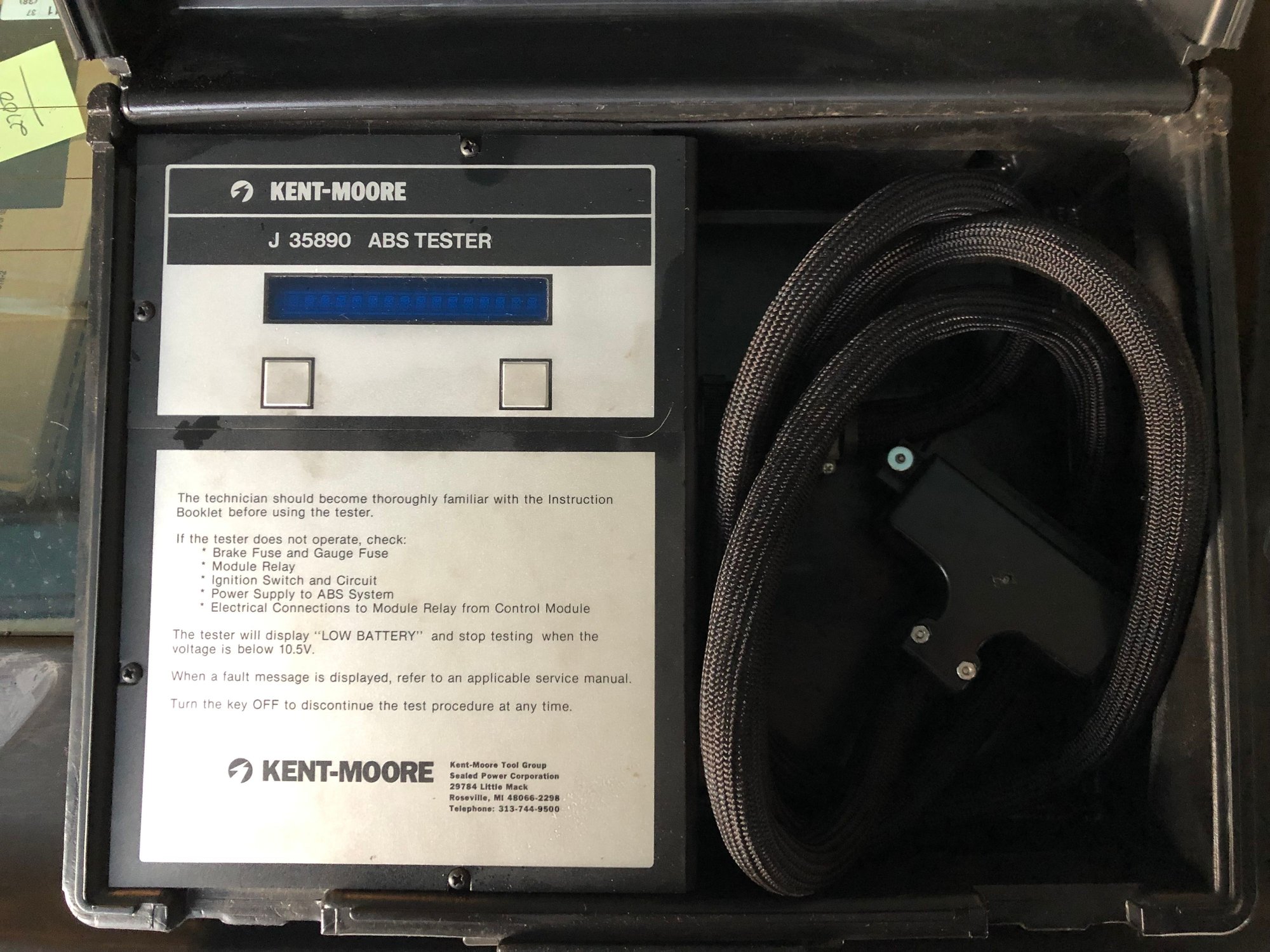
What I discovered during my search ( and this may be very common knowledge to others) is that the S3 ( and maybe other years) ABS brain is very similar or identical to the unit installed in '86 Corvettes.
What I discovered during my search ( and this may be very common knowledge to others) is that the S3 ( and maybe other years) ABS brain is very similar or identical to the unit installed in '86 Corvettes.
Lots of research and testing going on.
First thing: I was puzzled as I kept seeing slightly different documentation on Plug pin-outs for the S3 ABS harness to ABS Brain connector. Specifically the pins for the Right Front Sensor. Some sources state pins 21+23, some say 11+23 and one source said 11+21. Digging through the WSM Current Flow diagrams, it looks like it changed between 85 and 86:
85 Manual says 21+23:
The 86 WSM manual says 21+11, and also shows separate ground cables, so I am assuming they really mean 86.5 with the S4 style suspension and ABS:
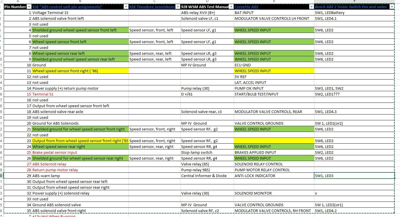
Next I compared the 928 pin-out to what I could find for the Vette ABS pin-out. They are essentially identical, with the Vette matching the 86 ( or 86.5) pin-out and adding input for Accelerator input to the ABS Brain ( by which we might infer that the Vette system was a little more advanced. ) Below is a shot of the spreadsheet I created comparing the various pin-outs from the various sources.
What the above means is that we _might_ be able to leverage some Vette tools to work on our ABS, with little or no modification. Vette tools should be cheaper and more plentiful that Porsche branded tools.
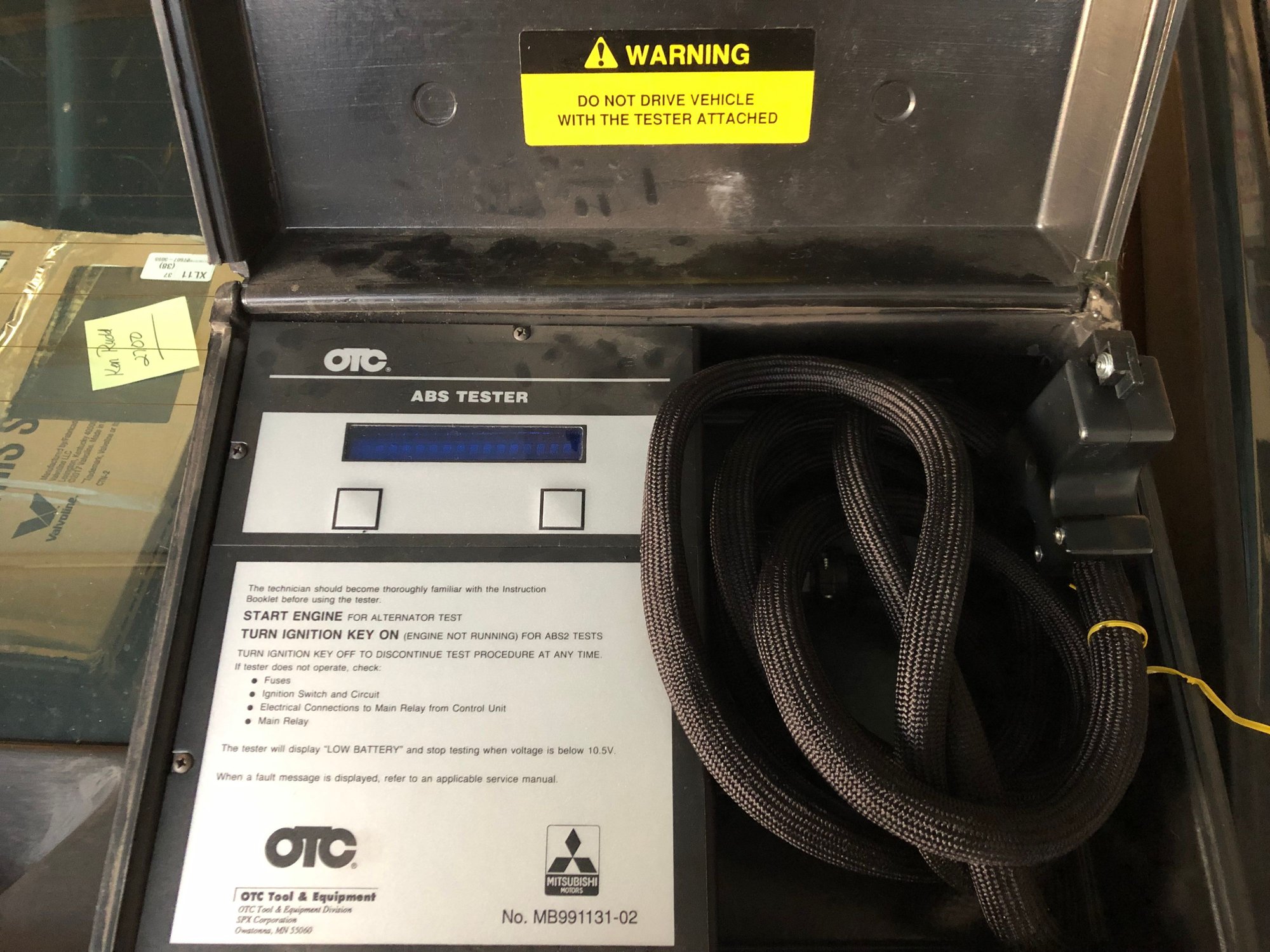
Those of you with sharp eyes will note my tester is slightly different than the one Greg posted, although they appear to have the exact same settings.
Also of note is the setting a **** position 4, aL and aQ. Those are to test the Transverse and Longitudinal Accelerometers ( which are not present in my car).
The above bank of lights show:
Voltage is Good
Ground 1 is Good
Ground 2 is Good
The Diode in the warning lamp circuit is good
The internal resistances/offposition for the solenoid valves on the hydraulic modulator are good. Sharp eyes will notice last bulb not lit. That is because we only have three channel output, Left Front, Right Front and Rear (Both).
We do have four channel sensor input though.


 10-24-2018, 02:19 PM