When you click on links to various merchants on this site and make a purchase, this can result in this site earning a commission. Affiliate programs and affiliations include, but are not limited to, the eBay Partner Network.
calling all electrical experts..........starter circuit problem
Hi all.
Firstly, I have an 84 Euro S.
Went I bought her, she had a push button ignition switch installed because the PO had problems with the starter circuit (key barrel or ignition switch) and decided to bypass this with a relay located next to the starter motor, and a push button hanging below the POD console.
I read a bit about the problems with the ignition switch, so decided to replace that when I did POD refurbish in an effort to begin to sort out the ignition problem. I have only now got around to re-instating the original wiring to the starter motor.
As it turns out, the only wire that was disconnected, was the yellow 'trigger' wire. I removed the two wires the PO had installed from his local relay, and reconnected the yellow one. Tried to start the car and the starter did not engage.
I pulled the CEP and the starter relay to check the circuit was working as designed and came across something I did not expect. This is where I need an expert to explain to me whats going on.
I got power to post 86 when engaging the key to "start position" so the ignition switch circuit works ok. But I've also got constant power to post 87.....????? Shouldnt this be post 30????? If power is going to the opposite side of the relay, will the relay actually still work?
I'm a real novice when it comes to 928 electrics, so will be lost if someone tells me the above is correct. Would it mean theres a break in the power circuit to the starter? But how would the bypassed switching circuit work then?
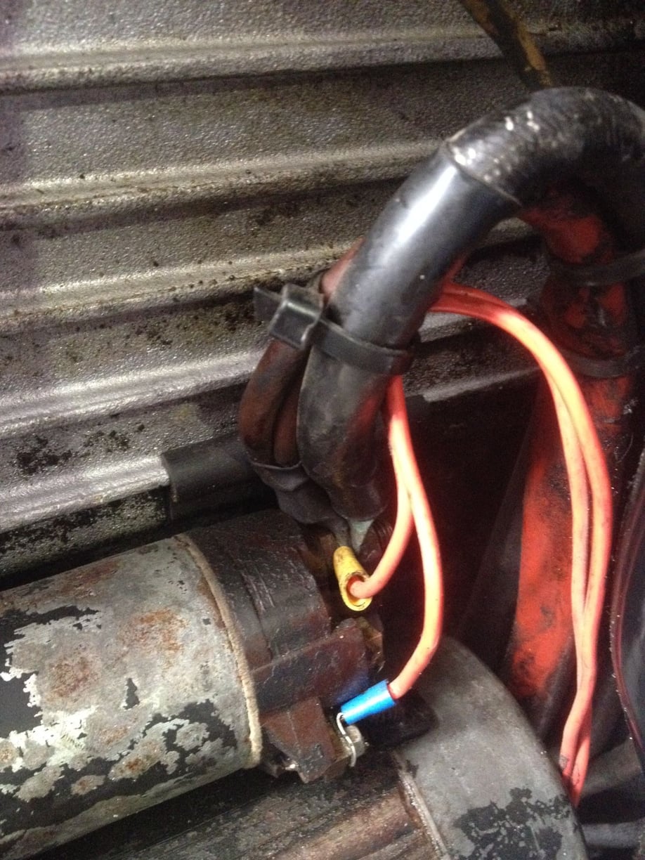
The pics attached is a photo of the current wiring (with the bypassed ignition circuit the red wires).
I got power to post 86 when engaging the key to "start position" so the ignition switch circuit works ok. But I've also got constant power to post 87.....????? Shouldnt this be post 30????? If power is going to the opposite side of the relay, will the relay actually still work?
I'm a real novice when it comes to 928 electrics, so will be lost if someone tells me the above is correct. Would it mean theres a break in the power circuit to the starter? But how would the bypassed switching circuit work then?
The relay works the same if power goes to 30 or 87 it's just a switch.
I assume you are measuring this on the relay socket with the relay removed?
In this case power should certainly only go to 30, are both 30 and 87 at 12v? 87 should be the yellow wire to the starter. Be sure you have the terminal ID correct - looking at the relay base pins is different than looking at the socket (flipped).
Check from the relay socket 87 to the CE pin O5, and on to the 14 pin engine loom connector (near the jump post) yellow wire, and on to the starter yellow wire. You need continuity all the way.
Also test for continuity (ohms mode) between the relay socket 85 pin and ground. Should be grounded in park but not in drive.
Thanks Alan, certainly points toward either no ground at 85 in park, or a break in the yellow wire from 05 to starter.
I'll try this out next weekend and report back.
Cheers
If you work through the tests it should be apparent what to do... Often there are problems with the 85 starter transmission lockout - but since you said jumping 30/87 on the starter relay didn't cause the starter to engage - it seems a break in the yellow wire is probably more likely here..
YTY many things change, you must always check the correct year wiring diagrams, sometimes the earlier current flow versions are indeed easier to read - but only useful if they are exact equivalents.
I tested the ground to pin 85 in park and its there (and is not when in D)
I went through some test and I've isolated the problem to the wire that comes from pin 87, through plug o5 and then to the 14pin connector. I am getting power to o5, but not post 14 on the connector. I will assume the wire has a break (even though it looks very thick and difficult to break), so if I run a new wire direct from pin o5 to the starter(bypassing the 14pin connector).....it should turn over..??
some side issues I dont quite understand. I did as suggested and checked connectivity all the way along from relay to starter. I checked each section individually and got between 0.9 and 1.9 ohms on each section. So I thought it might be the connector....TO test this, I managed to run a long wire from the starter end, all the way round to pin87 on the relay.........and connectivity was 0.2ohms. This suggested there was no break anywhere???????????
Also, for future reference, which side of the 14pin connector does the power run in (male or female plug). Its hard to trace the harness all the way back..
I decided to bypass the 14pin connector all together. Further tests concluded the yellow wire from O5 to connector was broken somewhere but trying to trace it from end to end to replace is almost impossible. My hands are all cut to piece just attempting (probably need to toughen them up considering future work required anyway).
SO I've run a 50Amp cable direct from O5 to the post on the Starter. Works great. The wiring diagram suggest the original yellow wire does not go anywhere else, so I figure its not a problem (except its not protected). But I've routed it through the firewall with other cabling and avoided any moving or hot parts.
SO thanks for steering me in the right direction. Cheers.
So...it ended up being the yellow wire from the 14 pin connection...like pictured in the wiring diagram... Brian.
The message stands - Wiring diagrams from different years are often actually DIFFERENT.
Here there was a starter and a yellow wire in both cases: both of those were slightly different - while everything else was totally different. But yes - I guess you were right all along...